Wiring Diagram Book - Schneider Electric
Wiring Diagram Book - Schneider Electric
Wiring Diagram Book - Schneider Electric

Create successful ePaper yourself
Turn your PDF publications into a flip-book with our unique Google optimized e-Paper software.
Terminology<br />
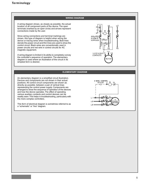
A wiring diagram shows, as closely as possible, the actual<br />
location of all component parts of the device. The open<br />
terminals (marked by an open circle) and arrows represent<br />
connections made by the user.<br />
Since wiring connections and terminal markings are<br />
shown, this type of diagram is helpful when wiring the<br />
device or tracing wires when troubleshooting. Bold lines<br />
denote the power circuit and thin lines are used to show the<br />
control circuit. Black wires are conventionally used in<br />
power circuits and red wire in control circuits for AC<br />
magnetic equipment.<br />
A wiring diagram is limited in its ability to completely convey<br />
the controller’s sequence of operation. The elementary<br />
diagram is used where an illustration of the circuit in its<br />
simplest form is desired.<br />
An elementary diagram is a simplified circuit illustration.<br />
Devices and components are not shown in their actual<br />
positions. All control circuit components are shown as<br />
directly as possible, between a pair of vertical lines<br />
representing the control power supply. Components are<br />
arranged to show the sequence of operation of the devices<br />
and how the device operates. The effect of operating<br />
various auxiliary contacts and control devices can be<br />
readily seen. This helps in troubleshooting, particularly with<br />
the more complex controllers.<br />
This form of electrical diagram is sometimes referred to as<br />
a “schematic” or “line” diagram.<br />
WIRING DIAGRAM<br />
ELEMENTARY DIAGRAM<br />
5