

Spiral Retaining Rings & Wave Springs - Bearing Engineers, Inc.
Spiral Retaining Rings & Wave Springs - Bearing Engineers, Inc.
Spiral Retaining Rings & Wave Springs - Bearing Engineers, Inc.

Create successful ePaper yourself
Turn your PDF publications into a flip-book with our unique Google optimized e-Paper software.
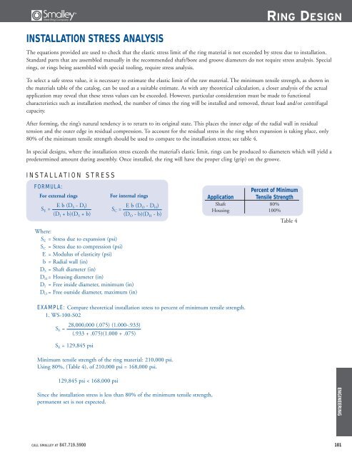
INSTALLATION STRESS ANALYSIS<br />
RING DESIGN<br />
The equations provided are used to check that the elastic stress limit of the ring material is not exceeded by stress due to installation.<br />
Standard parts that are assembled manually in the recommended shaft/bore and groove diameters do not require stress analysis. Special<br />
rings, or rings being assembled with special tooling, require stress analysis.<br />
To select a safe stress value, it is necessary to estimate the elastic limit of the raw material. The minimum tensile strength, as shown in<br />
the materials table of the catalog, can be used as a suitable estimate. As with any theoretical calculation, a closer analysis of the actual<br />
application may reveal that these stress values can be exceeded. However, particular consideration must be made to functional<br />
characteristics such as installation method, the number of times the ring will be installed and removed, thrust load and/or centrifugal<br />
capacity.<br />
After forming, the ring’s natural tendency is to return to its original state. This places the inner edge of the radial wall in residual<br />
tension and the outer edge in residual compression. To account for the residual stress in the ring when expansion is taking place, only<br />
80% of the minimum tensile strength should be used to compare to the installation stress; see table 4.<br />
In special designs, where the installation stress exceeds the material’s elastic limit, rings can be produced to diameters which will yield a<br />
predetermined amount during assembly. Once installed, the ring will have the proper cling (grip) on the groove.<br />
INSTALLATION STRESS<br />
FORMULA:<br />
For external rings For internal rings<br />
S E = E b (D S - D I)<br />
(D I + b)(D S + b)<br />
S C = E b (D O - D H)<br />
(D O - b)(D H - b)<br />
Where:<br />
S E = Stress due to expansion (psi)<br />
S C = Stress due to compression (psi)<br />
E = Modulus of elasticity (psi)<br />
b = Radial wall (in)<br />
D S = Shaft diameter (in)<br />
D H = Housing diameter (in)<br />
D I = Free inside diameter, minimum (in)<br />
D O = Free outside diameter, maximum (in)<br />
EXAMPLE: Compare theoretical installation stress to percent of minimum tensile strength.<br />
1. WS-100-S02<br />
S E =<br />
28,000,000 (.075) (1.000-.933)<br />
(.933 + .075)(1.000 + .075)<br />
S E = 129,845 psi<br />
Minimum tensile strength of the ring material: 210,000 psi.<br />
Using 80%, (Table 4), of 210,000 psi = 168,000 psi.<br />
129,845 psi < 168,000 psi<br />
Since the installation stress is less than 80% of the minimum tensile strength,<br />
permanent set is not expected.<br />
Percent of Minimum<br />
Application Tensile Strength<br />
Shaft 80%<br />
Housing 100%<br />
Table 4<br />
CALL SMALLEY AT 847.719.5900 101<br />
ENGINEERING