The Theory of the Microscope - Leica Microsystems
The Theory of the Microscope - Leica Microsystems
The Theory of the Microscope - Leica Microsystems

Create successful ePaper yourself
Turn your PDF publications into a flip-book with our unique Google optimized e-Paper software.
<strong>The</strong> <strong>The</strong>ory <strong>of</strong> <strong>the</strong> <strong>Microscope</strong><br />
Technisches Datenblatt
2<br />
<strong>The</strong> <strong>The</strong>ory <strong>of</strong> <strong>the</strong> <strong>Microscope</strong><br />
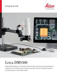
<strong>Leica</strong> <strong>Microsystems</strong> is a world leader <strong>of</strong> microscopes that combine high<br />
performance and practical design. <strong>The</strong> educational line <strong>of</strong>fers quality microscopes<br />
that withstand everyday student use at an affordable price. Teach<br />
beyond <strong>the</strong> regular microscopy applications with <strong>Leica</strong> educational products.<br />
1.0 Introduction........................................... 4<br />
2.0 What’s in a <strong>Microscope</strong> ................................ 4<br />
3.0 What Limits <strong>the</strong> Magnification .......................... 5<br />
4.0 Resolving Power....................................... 5<br />
5.0 Numerical Aperture.................................... 6<br />
6.0 Depth <strong>of</strong> Focus ........................................ 6<br />
7.0 Image Aberrations ..................................... 7<br />
8.0 Aberrations in <strong>the</strong> <strong>Microscope</strong> .......................... 9<br />
9.0 Apochromatic Objectives.............................. 10<br />
10.0 Types <strong>of</strong> Eyepieces.................................... 10<br />
11.0 Binocular Observation. ................................ 12<br />
12.0 <strong>The</strong> Illumination System ............................... 12<br />
13.0 Condenser Types ..................................... 13<br />
14.0 Critical Illumination ................................... 14<br />
15.0 Selective Filters ...................................... 15<br />
16.0 Darkfield Illumination ................................. 16<br />
17.0 Polarized Light. ....................................... 17<br />
18.0 Fluorescence Illumination ............................. 17<br />
19.0 Phase Contrast Microscopy. ........................... 17<br />
20.0 Concluding Remarks .................................. 19
ThE ThEORy OF ThE MICROSCOPE<br />
<strong>Leica</strong> DM750<br />
• Focusable or fixed eyepieces<br />
• Field <strong>of</strong> view <strong>of</strong> 20 mm<br />
• 45 degree tube<br />
• Wear resistant<br />
• Energy saving<br />
<strong>Leica</strong> DM500<br />
• No adjustment needed for parfocality<br />
with corrected vision<br />
• Large selection for different ergonomic<br />
requirements<br />
• Easy carrying and lifting onto high shelves<br />
• Patented captive thumb-screw for safe<br />
rotation <strong>of</strong> <strong>the</strong> EZTube<br />
<strong>Leica</strong> BM E<br />
• Superb, upgradeable <strong>Leica</strong> E series optics<br />
and performance at an excellent price<br />
• Tungsten-halogen illumination system<br />
provides lamp life <strong>of</strong> over 2,000 hours,<br />
12 W or a fluorescent system with 10,000<br />
hours life, 7 W<br />
• A wide variety <strong>of</strong> video and photography<br />
accessories provide flexibility<br />
• Designed to meet or exceed international<br />
electrical requirements<br />
<strong>Leica</strong> EZ4<br />
• Excellent three-dimensional viewing<br />
applications<br />
• Enclosed optical system resists damage<br />
and tampering<br />
• 4:1 zoom capability without losing focus<br />
• Effective three-way illumination system:<br />
transmitted, reflective or both<br />
<strong>Leica</strong> Camera Systems<br />
• Choose from <strong>Leica</strong>’s multi-purpose<br />
camera system or <strong>the</strong> high performance<br />
systems<br />
• Add accessories to your microscope<br />
to increase learning capabilities<br />
3
4<br />
Introduction<br />
<strong>The</strong> aim <strong>of</strong> this booklet is to provide <strong>the</strong> microscopist with a basic explanation <strong>of</strong> <strong>the</strong><br />
<strong>the</strong>ory <strong>of</strong> <strong>the</strong> microscope sufficient to enable him to understand <strong>the</strong> reasons behind<br />
accepted microscope techniques. It is felt that such an understanding will not only add to<br />
his interest in using <strong>the</strong> microscope, but will help him to work his way out <strong>of</strong> possible<br />
problems that may arise later on when detailed instructions, originally grasped, may have<br />
been forgotten. Where possible, ma<strong>the</strong>matical formulae have been avoided in favor <strong>of</strong><br />
physical or pictorial explanations, as it is felt that such explanations are more easily<br />
grasped and better retained than explanations involving ma<strong>the</strong>matics.<br />
2.0 What's in a <strong>Microscope</strong>?<br />
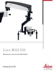
Figure 1 shows <strong>the</strong> way <strong>the</strong> lens elements <strong>of</strong> a microscope act to produce an enlarged<br />
image <strong>of</strong> a very tiny object. For <strong>the</strong> sake <strong>of</strong> clarity <strong>the</strong> 3 drawings are limited to strictly <strong>the</strong><br />
lens elements <strong>of</strong> <strong>the</strong> microscope. Later on we will describe <strong>the</strong> complete system, including<br />
<strong>the</strong> illumination system, <strong>the</strong> substage condenser, and <strong>the</strong> mirrors and prisms in <strong>the</strong> binocular<br />
body. At <strong>the</strong> right in Figure 1 is shown <strong>the</strong> traditional microscope. <strong>The</strong> objective acts<br />
much like a small projection lens, but instead <strong>of</strong> projecting an image onto a screen, it<br />
projects an enlarged primary image <strong>of</strong> <strong>the</strong> object up near <strong>the</strong> top <strong>of</strong> <strong>the</strong> microscope tube.<br />
This primary image is formed in <strong>the</strong> air and is called an “aerial image.” (<strong>The</strong> presence <strong>of</strong> this<br />
image could be shown by removing <strong>the</strong> eyepiece and putting a small translucent screen in<br />
<strong>the</strong> plane <strong>of</strong> this aerial image.) In actual use, however,we do not use a screen, we look at<br />
this imagethrough <strong>the</strong> eyepiece. This eyepiece acts very much like a magnifier, <strong>the</strong> principal<br />
difference being that it is used to magnify an aerial image instead <strong>of</strong> an actual object.<br />
<strong>The</strong> final image is formed on <strong>the</strong> retina <strong>of</strong> <strong>the</strong> eye, but appears to <strong>the</strong> eye to be in <strong>the</strong> plane<br />
<strong>of</strong> <strong>the</strong> Virtual Image down near <strong>the</strong> bottom <strong>of</strong> <strong>the</strong> diagram. This latter image is called a<br />
“virtual image” because <strong>the</strong> light rays do not actually come from this image, <strong>the</strong>y merely<br />
appear to come from it. <strong>The</strong> dashed lines going to <strong>the</strong> ends <strong>of</strong> this virtual image indicate<br />
that <strong>the</strong>se are not actual rays <strong>of</strong> light, merely extensions <strong>of</strong> <strong>the</strong> actual rays. <strong>The</strong> actual rays<br />
are shown in solid lines in between <strong>the</strong> eyepiece and <strong>the</strong> eye point. It is instructive to lay a<br />
straight edge along <strong>the</strong> dashed lines to get a clearer picture <strong>of</strong> <strong>the</strong> fact that <strong>the</strong>se are<br />
extensions <strong>of</strong> actual rays. <strong>The</strong> microscope attains its magnification in two stages. <strong>The</strong> first<br />
stage <strong>of</strong> magnification is produced by <strong>the</strong> objective, <strong>the</strong> second by <strong>the</strong> eyepiece. <strong>The</strong> final<br />
magnification is <strong>the</strong> product <strong>of</strong> <strong>the</strong>se two stages. If <strong>the</strong> objective magnification is 10 and<br />
<strong>the</strong> eyepiece magnification is 10, <strong>the</strong> final magnification is <strong>the</strong> product <strong>of</strong> <strong>the</strong> two, or 100.<br />
Figure 1<br />
RETINAL IMAGE<br />
EYEPOINT<br />
EYEPIECE<br />
OBJECTIVE<br />
OBJECT<br />
OPTICAL AXIS<br />
FIXED POWER<br />
MICROSCOPE<br />
FIELD<br />
DIAPHRAGM<br />
OBJECT PLANE<br />
VIRTUAL IMAGE
ThE ThEORy OF ThE MICROSCOPE<br />
3.0 What Limits<br />
<strong>the</strong> Magnification<br />
3.0 What limits <strong>the</strong> magnification? Actually <strong>the</strong>re is no upward limit to <strong>the</strong> magnification <strong>of</strong><br />
a microscope, <strong>the</strong>re is only a limit to <strong>the</strong> useful magnification. <strong>The</strong> basic limitation is not<br />
magnification, but resolving power, <strong>the</strong> ability <strong>of</strong> <strong>the</strong> microscope to render visible <strong>the</strong> fine<br />
detail <strong>of</strong> <strong>the</strong> object. If <strong>the</strong> object has been magnified to <strong>the</strong> point that its image is becoming<br />
fuzzy or indistinct due to <strong>the</strong> limited resolving power, fur<strong>the</strong>r magnification does nothing<br />
but make <strong>the</strong> image larger and less distinct without showing any more detail. Such useless<br />
increase in magnification is called “empty magnification,” meaning that it has exceeded<br />
<strong>the</strong> actual useful limit in showing specimen detail.<br />
4.0 Resolving Power<br />
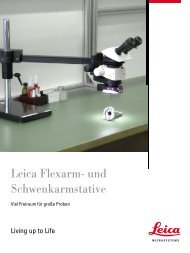
<strong>The</strong> resolving power <strong>of</strong> a microscope depends generally on <strong>the</strong> design <strong>of</strong> <strong>the</strong> objective. An<br />
objective capable <strong>of</strong> utilizing a large angular cone <strong>of</strong> light coming from <strong>the</strong> specimen will<br />
have better resolving power than an objective limited to a smaller cone <strong>of</strong> light. This is<br />
shown in <strong>the</strong> comparison pictures, Figure 2. <strong>The</strong> objective which picks up <strong>the</strong> larger cone<br />
<strong>of</strong> light gives considerably more detail in <strong>the</strong> image.<br />
<strong>The</strong> image <strong>of</strong> a point object is not a point but, due to <strong>the</strong> phenomenon <strong>of</strong> diffraction, is a<br />
small circular spot <strong>of</strong> light surrounded by rings <strong>of</strong> light as shown in Figure 3. This phenomenon<br />
was first ma<strong>the</strong>matically investigated by <strong>the</strong> astronomer Sir George Airy in 1834. he<br />
showed that <strong>the</strong> distribution <strong>of</strong> light in this pattern (which came to be known as <strong>the</strong> “Airy<br />
disk”) is such that <strong>the</strong> radius <strong>of</strong> <strong>the</strong> first dark ring (h’ in Figure 3) is a measure <strong>of</strong> <strong>the</strong> resolvable<br />
separation in <strong>the</strong> image. It can fur<strong>the</strong>r be shown that this separation in <strong>the</strong> image can<br />
be referred back to <strong>the</strong> object as a separation h defined by <strong>the</strong> equation:<br />
h = 0.61λ<br />
N.A.<br />
where λ is <strong>the</strong> wavelength <strong>of</strong> light (about 0.0005 mm or 0.00002”) and N.A. is <strong>the</strong><br />
“Numerical Aperture” <strong>of</strong> <strong>the</strong> objective.<br />
U<br />
U-6ϒ 54’<br />
NA=N sin U=0.12<br />
U<br />
U-14 ϒ 29’<br />
NA=N sin U=0.25<br />
Figure 2 Photomicrographs showing <strong>the</strong> dependence <strong>of</strong><br />
resolving power on numerical aperture (N.A.)<br />
Figure 3 <strong>The</strong> Airy disc. Photomicrograph <strong>of</strong> a pinhole in an aluminum<br />
mirror taken with a 4mm, 0.65 N.A. objective. h’, <strong>the</strong> radius <strong>of</strong> <strong>the</strong> first<br />
dark ring, is a measure <strong>of</strong> <strong>the</strong> resolving power.<br />
5
6<br />
5.0 Numerical Aperture<br />
<strong>The</strong> quantity N sin U in Figure 2 is called <strong>the</strong> Numerical Aperture or N.A. <strong>of</strong> an objective.<br />
Thus: N.A. = N sin U (by definition) where N is <strong>the</strong> refractive index in <strong>the</strong> object space.<br />
Manufacturers customarily engrave <strong>the</strong> N.A. on an objective, as it is an important characteristic<br />
<strong>of</strong> <strong>the</strong> lens. <strong>The</strong> higher <strong>the</strong> N.A. <strong>the</strong> more complex and expensive <strong>the</strong> lens system<br />
becomes,hence when buying a microscope it is wise to see that <strong>the</strong> N.A.s are up to standard<br />
practice.<br />
<strong>The</strong> equation h = 0.61λ<br />
N.A.<br />
indicates that <strong>the</strong> fineness <strong>of</strong> detail h which can be resolved is inversely proportional to<br />
<strong>the</strong> objective N.A.<br />
As indicated by <strong>the</strong> formula above, <strong>the</strong>re are three ways to increase resolving power, i.e.<br />
to decrease <strong>the</strong> resolvable separation h. <strong>The</strong> first method is to decrease <strong>the</strong> wavelength λ,<br />
<strong>the</strong> second is to increase <strong>the</strong> angle U in <strong>the</strong> object space (see Figure 2), and <strong>the</strong> third is to<br />
increase <strong>the</strong> index N in <strong>the</strong> object space.<br />
<strong>The</strong> wavelength λ can be decreased by going toward <strong>the</strong> violet, or short wavelength, end<br />
<strong>of</strong> <strong>the</strong> spectrum by means <strong>of</strong> selective filters. By means <strong>of</strong> special optics and special<br />
techniques, this effect can be extended into <strong>the</strong> ultraviolet for still fur<strong>the</strong>r lowering <strong>of</strong> <strong>the</strong><br />
resolvable separation.<br />
<strong>The</strong> angle U can be increased toward <strong>the</strong> 90° <strong>the</strong>oretical maximum, (i.e. N.A. = 1.00) only to<br />
a certain practical limit. <strong>The</strong> 0.95 N.A. apochromat represents a design giving <strong>the</strong> highest<br />
value<strong>of</strong> U which is practicable. N.A.’s higher than 0.95 are achieved by <strong>the</strong> use <strong>of</strong> immersion<br />
fluids, as explained in <strong>the</strong> next paragraph.<br />
<strong>The</strong> final method <strong>of</strong> decreasing <strong>the</strong> resolvable separation is to increase N, <strong>the</strong> index in <strong>the</strong><br />
object space. This is accomplished by “immersion objectives,” in which a fluid is used<br />
between <strong>the</strong> object slide and <strong>the</strong> front lens <strong>of</strong> <strong>the</strong> objective. <strong>The</strong> immersion fluid is normally<br />
oil (N = 1.52) although water (N = 1.33) and monobromonapthalene (N = 1.66) have<br />
also been used to some extent. By means <strong>of</strong> immersion fluids, objectives as high as 1.60<br />
N.A. have been produced, but <strong>the</strong> practicable limit has been found to be about 1.40 N.A.<br />
6.0 Depth <strong>of</strong> Focus<br />
When one focuses a microscope on an object, <strong>the</strong>re is a finite range above and below this<br />
object in which o<strong>the</strong>r objects appear in sharp focus. This range is called <strong>the</strong> depth <strong>of</strong> focus<br />
<strong>of</strong> <strong>the</strong> microscope. It varies markedly with objective N.A., in accordance with <strong>the</strong> relation:<br />
d = λ√N 2 – (NA) 2<br />
(NA) 2<br />
where d is <strong>the</strong> depth <strong>of</strong> focus for photomicrography. For visual use, one must add fur<strong>the</strong>r<br />
depth,since <strong>the</strong> eye is capable <strong>of</strong> a certain amount <strong>of</strong> accommodation. In this case, <strong>the</strong><br />
depth d’ becomes<br />
d’ = d + 250<br />
M 2<br />
where M is <strong>the</strong> magnification <strong>of</strong> <strong>the</strong> microscope. <strong>The</strong> assumption is made here that <strong>the</strong> eye<br />
can accommodate an image 250 mm away.<br />
Putting actual numbers in <strong>the</strong> above expression, we find that for <strong>the</strong> three most common<br />
objectives, we have <strong>the</strong> following depths <strong>of</strong> focus:<br />
Objective Eyepiece Depth <strong>of</strong> Focus<br />
Photomicro Visual<br />
10x, 0.25 N.A. 10x 0.0080 mm 0.0335 mm<br />
40x, 0.65 N.A. 10x 0.0010 mm 0.0026 mm<br />
100x, 1.25 N.A. 10x 0.0003 mm 0.0005 mm<br />
<strong>The</strong> visual depth <strong>of</strong> focus <strong>of</strong> <strong>the</strong> 100X, 1.25 N.A. oil-immersion objective is here shown to<br />
be only 0.0005 mm, or about a wavelength <strong>of</strong> light. This very tiny value indicates how<br />
closely one must focus when using such a high power objective, and indicates why a<br />
microscope needs a very finely controlled focusing motion.
ThE ThEORy OF ThE MICROSCOPE<br />
7.0 Image Aberrations<br />
<strong>The</strong> perfect lens system has yet to be designed. Lens systems all have aberrations or<br />
defects to a greater or lesser extent, depending on <strong>the</strong> skill <strong>of</strong> <strong>the</strong> designer and <strong>the</strong> magnitude<br />
<strong>of</strong> <strong>the</strong> lens design problem. Lens systems are composed <strong>of</strong> lenses having spherical<br />
surfaces, and a spherical surface does not form a perfect image. <strong>The</strong> lens designer, by<br />
judicious combinations <strong>of</strong> lens shapes and glass choices, is generally able to counteract<br />
<strong>the</strong> defects <strong>of</strong> one surface by equal and opposite defects in o<strong>the</strong>r surfaces, so that <strong>the</strong> end<br />
result approaches perfection, even though it never fully reaches this goal.<br />
<strong>The</strong> principal aberrations in <strong>the</strong> image formed by a spherical lens surface are:<br />
l. Spherical Aberration<br />
<strong>The</strong> (somewhat unfortunate) term used to express <strong>the</strong> fact that <strong>the</strong> outer portion <strong>of</strong> a<br />
spherical surface has more power than <strong>the</strong> inner portion. <strong>The</strong> lens designer overcomes<br />
this problem by judicious combinations <strong>of</strong> convergent and divergent lens elements, properly<br />
shaped to minimize <strong>the</strong> variation <strong>of</strong> focal power with aperture. Figure 4 shows <strong>the</strong><br />
appearance <strong>of</strong> <strong>the</strong> Airy disk (image <strong>of</strong> a point object) in <strong>the</strong> presence <strong>of</strong> spherical aberration.<br />
Note, by comparison with Figure 3, that spherical aberration has caused some <strong>of</strong> <strong>the</strong><br />
light which should be in <strong>the</strong> central spot to diffuse out into <strong>the</strong> ring structure. This undesirable<br />
diffusion causes a loss in contrast in <strong>the</strong> normal microscope preparation.<br />
2. Astigmatism<br />
is <strong>the</strong> defect whereby a marginal point object is drawn out into two separate line images<br />
lying at different distances from <strong>the</strong> lens surface. Like curvature <strong>of</strong> field, it results in a<br />
general deterioration <strong>of</strong> <strong>the</strong> <strong>of</strong>f-axis image, but unlike curvature <strong>of</strong> field, an astigmatic<br />
image can never be focused sharply except for <strong>the</strong> detail that is parallel or perpendicular<br />
to a radius <strong>of</strong> <strong>the</strong> field. Figure 5 shows <strong>the</strong> bad deterioration <strong>of</strong> <strong>the</strong> image <strong>of</strong> a point object<br />
(pinhole in an aluminum mirror) due to astigmatism.<br />
3. Coma<br />
is <strong>the</strong> name given to <strong>the</strong> defect in which different circular concentric zones <strong>of</strong> <strong>the</strong> lens<br />
surface give different magnifications to an <strong>of</strong>f-axis image. This defect results in a point<br />
object being imaged as a comet-shaped image, and, like <strong>the</strong> preceding two aberrations,<br />
causes <strong>the</strong> <strong>of</strong>f-axis image to deteriorate. Figure 6 shows <strong>the</strong> bad deterioration <strong>of</strong> <strong>the</strong> image<br />
<strong>of</strong> a point object due to <strong>the</strong> presence <strong>of</strong> coma. Coma in <strong>the</strong> center <strong>of</strong> <strong>the</strong>field is an indication<br />
<strong>of</strong> damage to <strong>the</strong> objective.<br />
Figure 4 <strong>The</strong> appearance <strong>of</strong> <strong>the</strong> Airy disk when spherical aberration is<br />
present.Photomicrograph taken with a 4 mm, 0.65 N.A. objective,<br />
purposely spaced incorrectly to show <strong>the</strong> effect <strong>of</strong> lens spacing on<br />
spherical aberration. Compare with Figure 3.<br />
Figure 5 <strong>The</strong> appearance <strong>of</strong> a point object due to <strong>the</strong> presence <strong>of</strong><br />
astigmatism. Compare with Figure 3.<br />
Figure 5 <strong>The</strong> appearance <strong>of</strong> a point object due to <strong>the</strong> presence <strong>of</strong> coma.<br />
Compare with Figure 3.<br />
7
8<br />
4. Distortion<br />
is <strong>the</strong> aberration which renders a square object as an image with curved sides, as shown<br />
in Figure 7, an image <strong>of</strong> a rectilinear cross-ruling. Note how <strong>the</strong> rulings near <strong>the</strong> edge<br />
appear curved inward. This is called “pincushion distortion.” <strong>The</strong> opposite effect is sometimes<br />
encountered, where <strong>the</strong> rulings appear to be curved outward, and in this case <strong>the</strong><br />
effect would be termed “barrel distortion.” Distortion is caused by <strong>the</strong> lens surface having<br />
different magnifications at <strong>the</strong> marginal and central portion <strong>of</strong> <strong>the</strong> image.<br />
5. Curvature <strong>of</strong> Field,<br />
as <strong>the</strong> name implies, is <strong>the</strong> aberration <strong>of</strong> a spherical lens surface which produces a curved<br />
image <strong>of</strong> a flat object due to <strong>the</strong> marginal portions <strong>of</strong> <strong>the</strong> image coming to a focus at a<br />
different distance than <strong>the</strong> central portions <strong>of</strong> <strong>the</strong> image. <strong>The</strong> end result is that when <strong>the</strong><br />
central part <strong>of</strong> <strong>the</strong> image is focused sharply <strong>the</strong> marginal portions are out <strong>of</strong> focus, and<br />
vice versa. Figure 8 shows <strong>the</strong> appearance <strong>of</strong> <strong>the</strong> same cross-ruling as in Figure 7, but<br />
taken with a lens having curvature <strong>of</strong> field.<br />
6. Chromatic Aberration<br />
is <strong>the</strong> property <strong>of</strong> a spherical lens surface which brings light <strong>of</strong> short wavelength to a focus<br />
closer than light <strong>of</strong> a longer wavelength. <strong>The</strong> defect is brought under control by proper<br />
combinations <strong>of</strong> glass types used in <strong>the</strong> convergent and divergent lens elements which<br />
make up <strong>the</strong> lens system.<br />
7. Lateral Color,<br />
or chromatic difference <strong>of</strong> magnification, results in light <strong>of</strong> one color being imaged at a<br />
greater magnification than light <strong>of</strong> ano<strong>the</strong>r color. This aberration causes an <strong>of</strong>f-axis image<br />
<strong>of</strong> a point object to be spread out into a tiny spectrum or spread <strong>of</strong> color.<br />
Figure 7 Distortion in a lens system causes straight lines to appear<br />
curved. Note curving lines at edges.<br />
Figure 8 Curvature <strong>of</strong> field. <strong>The</strong> center is sharply focused, <strong>the</strong> periphery<br />
is out <strong>of</strong> focus.
ThE ThEORy OF ThE MICROSCOPE<br />
8.0 Aberrations<br />
in <strong>the</strong> <strong>Microscope</strong><br />
Of all <strong>the</strong> aberrations, spherical aberration is <strong>the</strong> one which <strong>the</strong> microscopist should<br />
understand and know how to control. It manifests itself as a loss in contrast, giving a hazy<br />
appearance to <strong>the</strong> image. Assuming you have a good quality microscope, <strong>the</strong> presence <strong>of</strong><br />
spherical aberration usually indicates <strong>the</strong> use <strong>of</strong> <strong>the</strong> wrong coverglass thickness. <strong>The</strong><br />
proper coverglass thickness is engraved on <strong>the</strong> barrel <strong>of</strong> <strong>the</strong> objective, and this thickness<br />
should be used for best results. This is particularly true <strong>of</strong> <strong>the</strong> high powered dry objectives.<br />
Objectives are normally designed for 0.17 mm thick coverglasses, and any appreciable<br />
divergence from this thickness causes spherical aberration, particularly with <strong>the</strong><br />
high powered dry objectives, resulting in a “washed-out” image <strong>of</strong> low contrast.<br />
Astigmatism<br />
is normally present only to a minor degree in <strong>the</strong> <strong>of</strong>f-axis image. If present <strong>of</strong>f-axis, this is a<br />
design characteristic, and cannot be controlled by <strong>the</strong> microscopist. If present on-axis it is<br />
generally due to poor workmanship in <strong>the</strong> objective lens system.<br />
<strong>The</strong> same remarks on <strong>of</strong>f-axis astigmatism apply to <strong>of</strong>f-axis coma. <strong>The</strong> presence <strong>of</strong> coma<br />
on axis, however, is caused by decentration <strong>of</strong> some <strong>of</strong> <strong>the</strong> lens elements, and could<br />
indicate that <strong>the</strong> microscope has been mistreated.<br />
Distortion<br />
is normally under ra<strong>the</strong>r good control in a microscope. Some <strong>of</strong> <strong>the</strong> older negative lens<br />
systems used in photomicrography had considerable distortion, but even here, <strong>the</strong> types <strong>of</strong><br />
objects generally viewed did not put very severe demands on <strong>the</strong> distortion correction,<br />
and such lenses were generally quite acceptable.<br />
Curvature <strong>of</strong> Field<br />
has long been <strong>the</strong> most difficult aberration to contend with in microscope design. This was<br />
particularly true <strong>of</strong> <strong>the</strong> high powered objectives, where <strong>the</strong> extremely strong front elements<br />
left <strong>the</strong> designer with an almost hopeless task <strong>of</strong> correcting <strong>the</strong> field curvature. In<br />
<strong>the</strong> 1950’s and 1960’s various elaborate objectives having good flat field correction were<br />
introduced as premium priced items by several microscope manufacturers. 1965 ushered<br />
in a new era in microscope objective design with <strong>the</strong> introduction <strong>of</strong> flat-field objectives to<br />
replace <strong>the</strong> conventional achromatic series <strong>of</strong> objectives. In this new design concept, a 5X<br />
negative doublet lens system acts as a component <strong>of</strong> each <strong>of</strong> <strong>the</strong> objectives. (By taking<br />
over a portion <strong>of</strong> <strong>the</strong> magnification burden, this 5X system eased <strong>the</strong> magnification requirements<br />
on <strong>the</strong> objectives, and permitted <strong>the</strong> attainment <strong>of</strong> flat fields without <strong>the</strong><br />
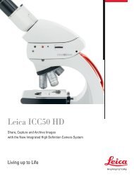
extreme complexity and cost <strong>of</strong> prior systems.) Figure 9 shows <strong>the</strong> conventional achromatic<br />
series <strong>of</strong> objectives, standard for many years on all laboratory microscopes. Figure<br />
10, for comparison, shows <strong>the</strong> newer flat-field objective series wherein <strong>the</strong> upper doublet<br />
is a common lens system for each <strong>of</strong> <strong>the</strong> objectives.<br />
Note that in <strong>the</strong> higher powered flat-field objectives <strong>the</strong> front element is a thick meniscus<br />
lens, whereas in <strong>the</strong> older achromatic series <strong>the</strong> front element is a very strong hemisphere.<br />
This latter element was <strong>the</strong> principal cause <strong>of</strong> curvature <strong>of</strong> field in <strong>the</strong> older series.<br />
Figure 9 A series <strong>of</strong> achromatic objectives.<br />
9
10<br />
Chromatic Aberration<br />
is normally not present to any appreciable degree in a well made microscope, whereas<br />
lateral color may <strong>of</strong>ten be found, particularly where <strong>the</strong> incorrect combination <strong>of</strong> objective<br />
and eyepiece is used. With <strong>the</strong> older achromatic series, Figure 9, <strong>the</strong> correction for lateral<br />
color was different from one objective to ano<strong>the</strong>r, so that one usually compromised on<br />
lateral color in selecting an eyepiece for this series. With <strong>the</strong> new flat-field series, Figure<br />
10, <strong>the</strong> degree <strong>of</strong> correction for lateral color is constant, and one eyepiece serves for <strong>the</strong><br />
entire series. Note that <strong>the</strong> 4X objective in <strong>the</strong> flat-field series is more complex than its<br />
counterpart in <strong>the</strong> achromatic series. This is due to <strong>the</strong> design requirement that <strong>the</strong> entire<br />
series should have <strong>the</strong> same lateral color correction.<br />
9.0 Apochromatic Objectives<br />
A good many years ago it was found that an objective lens system which combined fluorite<br />
with glass lenses achieved an improvement over what was possible in <strong>the</strong> achromats,<br />
which were restricted to glass elements only. Such lenses became known as “fluorites”<br />
and “apochromats.” <strong>The</strong> fluorites are sometimes called “semi-apochromats” as <strong>the</strong>y<br />
represent a compromise between <strong>the</strong> achromat and apochromat in <strong>the</strong>ir degree <strong>of</strong> correction.<br />
Apochromats are superior to achromats in <strong>the</strong>ir correction for spherical and chromatic<br />
aberration. Also, <strong>the</strong>y are generally somewhat higher in N.A., hence have superior<br />
resolving power. Figure 11 shows a series <strong>of</strong> four apochromats, which may be compared<br />
with Figure 9. <strong>The</strong> shaded elements in Figure 11 represent lenses made <strong>of</strong> fluorite.<br />
10.0 Types <strong>of</strong> Eyepieces<br />
As pointed out in <strong>the</strong> early sections <strong>of</strong> this booklet, <strong>the</strong> eyepiece is essentially a magnifier<br />
to enlarge <strong>the</strong> image formed by <strong>the</strong> objective. <strong>The</strong> least expensive and most widely used<br />
eyepiece is <strong>the</strong> Huygenian type, (Figure 12), named after its inventor, Christian Huygens, a<br />
famous Dutch scientist <strong>of</strong> <strong>the</strong> 17th century. <strong>The</strong> huygenian eyepiece works well with <strong>the</strong><br />
flat-field series and <strong>the</strong> low power achromats, but is afflicted with some lateral color when<br />
used with higher power achromats or apochromats. Its field <strong>of</strong> view is not large, and has a<br />
ra<strong>the</strong>r short eye relief. Despite <strong>the</strong>se shortcomings it finds wide acceptance because it is<br />
inexpensive and generally gives a very credible image.<br />
4.50 mm FIELD<br />
4.0 X 0.09 N.A .<br />
FLAT FIELD<br />
1.80 mm FIELD<br />
10 X 0.25 N.A .<br />
FLAT FIELD<br />
Figure 10 A series <strong>of</strong> flat-field objectives.<br />
FIELD 1.8MM<br />
10X, 0.30 N.A .<br />
APOCHROMAT<br />
FIELD 0.9M M<br />
20X, 0.65 N.A .<br />
APOCHROMAT<br />
Figure 11 A series <strong>of</strong> apochromatic objectives.<br />
0.90 mm FIELD<br />
20 X 0.50 N.A .<br />
FLAT FIELD<br />
FIELD 0.38M M<br />
47X, 0.95 N.A .<br />
APOCHROMAT<br />
0.45 mm FIELD<br />
4.0 X 0.65 N.A .<br />
FLAT FIELD<br />
0.18 mm FIELD<br />
100 X 1.25 N.A .<br />
FLAT FIELD<br />
FIELD 0.30M M<br />
61X, 1.40 N.A .<br />
APOCHROMAT<br />
OIL<br />
OIL
ThE ThEORy OF ThE MICROSCOPE<br />
<strong>The</strong> huygenian eyepiece utilizes two simple lenses to achieve its correction for lateral<br />
color. <strong>The</strong> light going through <strong>the</strong> first lens, called <strong>the</strong> “field-lens”, is spread out into a<br />
spectrum with red at one limit and blue at <strong>the</strong> o<strong>the</strong>r. However, by proper spacing <strong>of</strong> <strong>the</strong><br />
lenses, <strong>the</strong> red light is caused to strike <strong>the</strong> second lens, called <strong>the</strong> “eyelens” at a sufficiently<br />
greater height than <strong>the</strong> blue to compensate <strong>the</strong> angular spread between <strong>the</strong> rays<br />
and cause <strong>the</strong> red and blue rays to emerge parallel, as shown in Figure 12. To <strong>the</strong> eye,<br />
focused for infinity, <strong>the</strong> red and blue rays unite on <strong>the</strong> retina to form a color free image.<br />
<strong>The</strong> widefield eyepiece, designed originally for stereomicroscopes, has subsequently been<br />
modified to work with <strong>the</strong> conventional laboratory microscopes. It is gradually supplanting<br />
huygenian eyepieces because <strong>of</strong> its larger field <strong>of</strong> view and more comfortable eye-relief.<br />
Its lateral color correction is close to that <strong>of</strong> <strong>the</strong> Huygenian eyepiece, hence it works well<br />
with <strong>the</strong> flat-field objectives. A special version <strong>of</strong> this eyepiece is available for use with <strong>the</strong><br />
zooming microscopes to get <strong>the</strong> optimum lateral color correction in this application. Figure<br />
13 shows <strong>the</strong> two versions <strong>of</strong> <strong>the</strong> widefield eyepiece, one for <strong>the</strong> fixed power microscopes<br />
and <strong>the</strong> o<strong>the</strong>r for <strong>the</strong> zooming microscopes.<br />
<strong>The</strong> Hyperplane and Compensating eyepieces, Figure 14, are similar in construction to <strong>the</strong><br />
Huygenian eyepiece, except that <strong>the</strong> eyelens is a doublet. This construction gives more<br />
lateral color correction, as indicated in <strong>the</strong> figure. <strong>The</strong> compensating type gives <strong>the</strong> most<br />
correction for lateral color, <strong>the</strong> Hyperplane being a compromise between <strong>the</strong> Huygenian<br />
and <strong>the</strong> Compensating in this regard. Note that in Figure 14 <strong>the</strong> red and blue rays are<br />
shown aimed at different heights in <strong>the</strong> primary image, due to <strong>the</strong> objective having undercorrected<br />
lateral color.<strong>The</strong> eyepiece compensates for this, and causes <strong>the</strong> red and blue<br />
rays to emerge parallel so that <strong>the</strong>y unite in a single color-free image on <strong>the</strong> retina <strong>of</strong> <strong>the</strong><br />
eye. <strong>The</strong> higher power eyepieces in both <strong>the</strong> hyperplane and Compensating series are <strong>of</strong> a<br />
more complex form than indicated in Figure 14.<br />
In photomicrography special divergent (negative) lens systems are frequently used in<br />
place <strong>of</strong> <strong>the</strong> traditional eyepieces. In <strong>the</strong>se systems <strong>the</strong>re is no intermediate formation <strong>of</strong><br />
an image as in an ordinary eyepiece. Instead, <strong>the</strong> image is intercepted before it comes to<br />
focus, and projected outward to <strong>the</strong> photographic film. Typical <strong>of</strong> such divergent lens<br />
systems are <strong>the</strong> Ultraplanes, available in three different degrees <strong>of</strong> lateral color compensation,<br />
for use with external cameras and for objectives ranging from low power achromats<br />
to high power apochromats. <strong>The</strong> modern built-in camera also utilizes this divergent<br />
lens concept. here <strong>the</strong> system is corrected for use with <strong>the</strong> entire flat-field series <strong>of</strong><br />
objectives. It is permanently aligned, and permanently parfocalized with <strong>the</strong> binocular<br />
viewing system, so that <strong>the</strong> binocular may be used as <strong>the</strong> focusing viewfinder for <strong>the</strong><br />
camera.<br />
Figure 12 General construction <strong>of</strong> <strong>the</strong> huygenian eyepiece.<br />
BLUE<br />
RED<br />
RED<br />
BLUE<br />
RED<br />
BLUE<br />
RED<br />
BLUE<br />
RED<br />
BLUE<br />
Figure 13 Two forms <strong>of</strong> widefield eyepieces. <strong>The</strong> lower one has a lateral color correcting doublet added, for<br />
optimum performance with <strong>the</strong> zooming microscopes.<br />
BLUE<br />
RED<br />
BLUE IMAGE<br />
RED IMAGE<br />
Figure 14 General construction <strong>of</strong> <strong>the</strong> low power hyperplane and Compensating eyepieces<br />
11
12<br />
11.0 Binocular Observation<br />
Thus far we have considered only <strong>the</strong> monocular microscope. For prolonged use, <strong>the</strong><br />
inclined binocular form is preferred since it gives a more natural and restful condition <strong>of</strong><br />
observation. Figure 15 shows a cutaway view <strong>of</strong> <strong>the</strong> optical system <strong>of</strong> a binocular microscope.<br />
Binocular vision is attained by <strong>the</strong> use <strong>of</strong> a beam-dividing prism and three mirrors.<br />
This system divides <strong>the</strong> light equally, sending half to <strong>the</strong> left eye and half to <strong>the</strong> right. <strong>The</strong><br />
coating on <strong>the</strong> mirrors is enhanced aluminum, having a multiple-film transparent coating<br />
on top <strong>of</strong> <strong>the</strong> aluminum to increase <strong>the</strong> reflectivity and protect <strong>the</strong> aluminum. Coverglass<br />
seals are used to keep dust from entering <strong>the</strong> binocular body.<br />
12.0 <strong>The</strong> Illumination System<br />
<strong>The</strong> illumination system is a very important part <strong>of</strong> <strong>the</strong> microscope. It is <strong>the</strong> part with<br />
which <strong>the</strong> operator can do most in controlling <strong>the</strong> microscope performance, and is at <strong>the</strong><br />
same time probably <strong>the</strong> least understood part <strong>of</strong> <strong>the</strong> microscope. It has been pointed out in<br />
<strong>the</strong> preceding sections that <strong>the</strong> resolving power depends on <strong>the</strong> N.A. <strong>of</strong> <strong>the</strong> objective. To<br />
get <strong>the</strong> most out <strong>of</strong> <strong>the</strong> objective, <strong>the</strong> condenser system must be capable <strong>of</strong> delivering as<br />
large an angular cone <strong>of</strong> light as <strong>the</strong> objective is capable <strong>of</strong> utilizing.<br />
This statement should not be interpreted as meaning that <strong>the</strong> full N.A. <strong>of</strong> <strong>the</strong> objective<br />
should always be illuminated. Generally speaking, full N.A. illumination is not used, because<br />
contrast drops as <strong>the</strong> illuminated N.A. approaches <strong>the</strong> full objective N.A. Each<br />
specimen is a law unto itself in regard to <strong>the</strong> proper illuminating N.A. With high contrast<br />
specimens having very fine detail one would want to use very close to full N.A. illumination,<br />
but with low contrast objects,<strong>the</strong> illuminated N.A. would have to be reduced to<br />
prevent complete “washing out” <strong>of</strong> <strong>the</strong> image due to low contrast.<br />
<strong>The</strong> illuminated N.A. is controlled by means <strong>of</strong> <strong>the</strong> substage iris. It is instructive to remove<br />
<strong>the</strong> eyepiece and look at <strong>the</strong> back lens <strong>of</strong> <strong>the</strong> objective while opening and closing <strong>the</strong><br />
substage iris. An image <strong>of</strong> <strong>the</strong> iris will be seen in focus close to <strong>the</strong> back lens <strong>of</strong> <strong>the</strong> objective.<br />
Full-aperture illumination occurs when <strong>the</strong> iris is opened up just enough to include <strong>the</strong><br />
full aperture <strong>of</strong> <strong>the</strong> objective lens.<br />
Closing down <strong>the</strong> illuminated N.A. excessively is a common fault with beginners in microscopy.<br />
<strong>The</strong> contrast gets very good by so doing, but at a loss in resolution. <strong>The</strong> loss in<br />
resolution is not so easy to notice as <strong>the</strong> gain in contrast. Excessive closing down <strong>of</strong> <strong>the</strong><br />
illuminated N.A. also gives rise to image artifacts due to diffraction. <strong>The</strong> experienced<br />
microscopist learns to make <strong>the</strong> optimum setting for illuminated N.A. as a best compromise<br />
between resolving power and contrast. Where <strong>the</strong> microscope illuminator has an iris<br />
diaphragm, it is intended to be used to control <strong>the</strong> size <strong>of</strong> <strong>the</strong> illuminated field <strong>of</strong> view on<br />
<strong>the</strong> specimen. <strong>The</strong> substage condenser should be adjusted to form a sharp image <strong>of</strong> <strong>the</strong><br />
lamp iris on <strong>the</strong> specimen plane. <strong>The</strong> size <strong>of</strong> <strong>the</strong> iris should <strong>the</strong>n be adjusted to lie just<br />
outside <strong>the</strong> field <strong>of</strong> view <strong>of</strong> <strong>the</strong> microscope.
ThE ThEORy OF ThE MICROSCOPE<br />
13.0 Condenser Types<br />
<strong>The</strong> function <strong>of</strong> <strong>the</strong> substage condenser is to direct a light beam <strong>of</strong> <strong>the</strong> desired N.A. and<br />
field size onto <strong>the</strong> specimen. <strong>The</strong>re are several types <strong>of</strong> condensers, three <strong>of</strong> which are<br />
shown in Figure 16.<br />
<strong>The</strong> Abbe Condenser is a 1.30 N.A. condenser utilizing only two lenses. Because <strong>of</strong> its<br />
simplicity and good light-ga<strong>the</strong>ring ability, it has become extensively used for general<br />
microscopy. It is, <strong>of</strong> course, not corrected for spherical or chromatic aberration, but for<br />
general visual observation it serves very well.<br />
<strong>The</strong> Variable Focus Condenser is a two-lens condenser, 1.30 N.A. maximum in which <strong>the</strong><br />
upper lens element is fixed and <strong>the</strong> lower one focusable. By this means it is possible to fill<br />
<strong>the</strong> field <strong>of</strong> low power objectives without <strong>the</strong> necessity <strong>of</strong> removing <strong>the</strong> top element when<br />
<strong>the</strong> lower lens is raised to its top position. This condenser is basically similar to <strong>the</strong> 1.30<br />
N.A. Abbe. When <strong>the</strong> focusable lens is lowered, <strong>the</strong> focus <strong>of</strong> <strong>the</strong> light is brought in between<br />
<strong>the</strong> elements, and when this focus is at <strong>the</strong> point indicated in <strong>the</strong> diagram, <strong>the</strong> light<br />
emerges as a large diameter parallel bundle.<br />
<strong>The</strong> Achromatic Condenser is a 1.40 N.A. condenser which is corrected for both chromatic<br />
and spherical aberrations. Because <strong>of</strong> its high degree <strong>of</strong> correction it is recommended for<br />
research microscopy and color photomicrography where <strong>the</strong> highest degree <strong>of</strong> perfection<br />
in <strong>the</strong> image is desired.<br />
It will be recalled, from <strong>the</strong> previous discussion on immersion objectives, that to obtain<br />
N.A.’s over about 0.95 it is necessary to oil-contact <strong>the</strong> lens system to <strong>the</strong> specimen slide.<br />
A drop <strong>of</strong> immersion oil, placed on <strong>the</strong> lower surface <strong>of</strong> <strong>the</strong> object slide or <strong>the</strong> upper surface<br />
<strong>of</strong> <strong>the</strong> condenser hemisphere, achieves this result.<br />
Generally it is not necessary to immerse <strong>the</strong> condenser, but special tasks occasionally do<br />
require immersion for optimum results.<br />
Figure 16 Condenser types.<br />
OBJECT<br />
SLIDE<br />
OBJECT<br />
SLIDE<br />
STATIONARY<br />
ELEMENT<br />
FOCUSABLE<br />
ELEMENT<br />
OBJECT<br />
SLIDE<br />
13
14<br />
14.0 Critical Illumination<br />
Critical illumination is a form <strong>of</strong> illumination in which <strong>the</strong> light source is imaged directly on<br />
<strong>the</strong> specimen. It is used in high power microscopy, microprojection, and photomicrography,<br />
where an intense and controlled beam <strong>of</strong> light is necessary. Critical illumination was<br />
held in highest regard for many years, as early <strong>the</strong>oretical consideration indicated that it<br />
should permit higher resolving power than o<strong>the</strong>r forms <strong>of</strong> illumination. <strong>The</strong> reasoning for<br />
this was founded on <strong>the</strong> <strong>the</strong>oretical basis that two adjoining points in a specimen could be<br />
better resolved if <strong>the</strong>ir illuminated background had no point-to-point phase relationship.<br />
Such a background is provided by critical illumination where a source is imaged directly on<br />
<strong>the</strong> specimen, since <strong>the</strong> various points <strong>of</strong> a light source have <strong>the</strong> completely random phase<br />
distribution characteristic <strong>of</strong> <strong>the</strong>rmal emission. With <strong>the</strong> passage <strong>of</strong> years, critical illumination<br />
has been gradually replaced by ano<strong>the</strong>r intense form <strong>of</strong> illumination known as<br />
Koehler Illumination. <strong>The</strong> two systems are shown in Figure 17.<br />
Koehler illumination presents certain advantages over critical illumination and has gradually<br />
replaced <strong>the</strong> latter. With <strong>the</strong> Koehler system, inclusion <strong>of</strong> field diaphragm control is<br />
made feasible. Ano<strong>the</strong>r advantage <strong>of</strong> <strong>the</strong> Koehler system is that uneven distribution <strong>of</strong><br />
energy in <strong>the</strong> source does not result in uneven brightness in <strong>the</strong> field <strong>of</strong> view, since <strong>the</strong><br />
source is imaged in <strong>the</strong> aperture <strong>of</strong> <strong>the</strong> system. <strong>The</strong>se practical advantages have led to <strong>the</strong><br />
gradual replacement <strong>of</strong> critical illumination by Koehler illumination, and when M. Berek<br />
showed that <strong>the</strong> two systems were <strong>the</strong>oretically equivalent in resolving power, <strong>the</strong> final<br />
argument favoring critical illumination was removed.<br />
Many modern microscopes utilize built-in illumination systems. <strong>The</strong>se are permanently<br />
aligned so that centering by <strong>the</strong> microscopist is not necessary. Usually <strong>the</strong>y employ a low<br />
voltage concentrated filament lamp so that high brightness levels may be attained. Optically<br />
<strong>the</strong>y are <strong>the</strong> equivalent <strong>of</strong> <strong>the</strong> Koehler system shown in <strong>the</strong> lower half <strong>of</strong> Figure 17, but<br />
one <strong>of</strong> <strong>the</strong> lamp condensers is invariably frosted to produce even illumination at all microscope<br />
powers, and <strong>the</strong> mirror is factory adjusted to give permanent centration to <strong>the</strong><br />
illuminating beam.<br />
SOURCE IMAGED IN<br />
SPECIMEN PLATE<br />
LAMP CONDENSER IMAGED<br />
IN SPECIMEN PLANE<br />
SOURCE IMAGED IN<br />
APERTURE DIAPHRAGM<br />
Figure 17 Illustrating both Critical and Koehler illumination.<br />
CRITICAL ILLUMINATION<br />
FIELD DIAPHRAG M<br />
KOEHLER ILLUMINATION
ThE ThEORy OF ThE MICROSCOPE<br />
15.0 Selective Filters<br />
Contrast in <strong>the</strong> image <strong>of</strong> a colored microscope preparation can be controlled by <strong>the</strong> use <strong>of</strong><br />
colored or selective filters. If, for example, <strong>the</strong> microscope preparation consists <strong>of</strong> red and<br />
blue areas, use <strong>of</strong> a red filter, which absorbs <strong>the</strong> blue but not <strong>the</strong> red, will darken <strong>the</strong> blue<br />
areas and cause <strong>the</strong> red areas to stand out bright by contrast with <strong>the</strong> blue. This type <strong>of</strong><br />
contrast control is particularly useful in photomicrography and a set <strong>of</strong> selective filters is,<br />
accordingly, generally supplied with photomicrographic equipment. Colored glass filters<br />
and colored gelatine filters have been used extensively for this purpose in <strong>the</strong> past, but<br />
ano<strong>the</strong>r type, operating on <strong>the</strong> principle <strong>of</strong> interference, has advantages over <strong>the</strong>se, and<br />
will be described in <strong>the</strong> following section.<br />
Interference filters utilize <strong>the</strong> principle <strong>of</strong> optical interference to accomplish selective or<br />
colored transmission. <strong>The</strong> principle is illustrated in Figure 18. In <strong>the</strong> upper part <strong>of</strong> this<br />
figure, <strong>the</strong> effect <strong>of</strong> adding two waves which are in phase is shown to result in a wave<br />
which is additive. <strong>The</strong> converse situation, where <strong>the</strong> waves are out <strong>of</strong> phase, is shown to<br />
result in destructive interference, or darkness. <strong>The</strong> former case is generally more easily<br />
understood than <strong>the</strong> latter. <strong>The</strong> “destruction” <strong>of</strong> energy by o<strong>the</strong>r energy is, however,<br />
understandable if labeled as a “redistribution” ra<strong>the</strong>r than a “destruction” <strong>of</strong> energy. <strong>The</strong><br />
energy actually reappears elsewhere. For example, if destructive interference at a surface<br />
causes <strong>the</strong> transmitted energy to lessen, it will at <strong>the</strong> same time cause <strong>the</strong> reflected<br />
energy to increase. <strong>The</strong> interference filter utilizes this principle to accomplish conductive<br />
interference for a narrow band in <strong>the</strong> visual spectrum and destructive interference for <strong>the</strong><br />
rest <strong>of</strong> <strong>the</strong> spectrum, so that only a narrow band <strong>of</strong> colored light is passed by <strong>the</strong> filter. <strong>The</strong><br />
filter is composed <strong>of</strong> two semitransparent silver layers separated by a thin layer <strong>of</strong> transparent<br />
material (magnesium fluoride generally). <strong>The</strong> thickness <strong>of</strong> <strong>the</strong> transparent layer is<br />
so controlled that multiple reflections between <strong>the</strong> silver layers are in a state <strong>of</strong> constructive<br />
interference in <strong>the</strong> transmitted beam for some chosen wavelength. <strong>The</strong> thickness<br />
chosen is slightly too great for constructive interference <strong>of</strong> shorter wavelengths, and<br />
slightly too small for longer wavelengths. As a consequence only wavelengths close to <strong>the</strong><br />
desired wavelength get through <strong>the</strong> filter. <strong>The</strong> spectral transmission curve <strong>of</strong> a typical<br />
interference filter is shown in Figure 18.<br />
CONSTRUCTIVE (ADDITIVE) INTERFERENCE A+ A=2A<br />
DESTRUCTIVE (SUBTRACTIVE) INTERFERENCE A- A=0<br />
30<br />
20<br />
10<br />
0 400m 500m 600m 700m<br />
A<br />
A<br />
2A<br />
A<br />
A<br />
ZERO<br />
Figure 18 Interference filters utilize <strong>the</strong> principle <strong>of</strong> optical interference to accomplish selective or colored<br />
transmission.<br />
15
16<br />
16.0 Darkfield Illumination<br />
Two types <strong>of</strong> darkfield condensers are shown in Figure 19. <strong>The</strong>se produce an intense<br />
hollow cone <strong>of</strong> light with its apex (or focal point) in <strong>the</strong> plane <strong>of</strong> <strong>the</strong> specimen. If <strong>the</strong> specimen<br />
is completely transparent and homogeneous, <strong>the</strong> light continues directly on through<br />
and does not enter <strong>the</strong> objective, since <strong>the</strong> N.A. <strong>of</strong> <strong>the</strong> illuminating cone exceeds that <strong>of</strong><br />
<strong>the</strong> objective. <strong>The</strong> field <strong>of</strong> view will thus look dark. If, however, <strong>the</strong> specimen has fine<br />
transparent detail which differs in refractive index from <strong>the</strong> embedding medium, it will<br />
scatter light due to refraction and reflection, and will appear bright, since some <strong>of</strong> this<br />
scattered light will enter <strong>the</strong> objective. This type <strong>of</strong> illumination, known as “darkfield,” is<br />
useful principally on transparent unstained material where brightfield illumination fails to<br />
make <strong>the</strong> object visible due to <strong>the</strong> low contrast. Figure 20 is a photomicrograph <strong>of</strong> such a<br />
specimen taken in darkfield illumination.<br />
Darkfield condensers depend on <strong>the</strong> use <strong>of</strong> a high N.A. hollow cone <strong>of</strong> light, and must be<br />
oil-contacted to <strong>the</strong> lower face <strong>of</strong> <strong>the</strong> object slide in order to obtain <strong>the</strong> required N.A. in <strong>the</strong><br />
illuminated cone. It is also, <strong>of</strong> course, necessary to use an objective <strong>of</strong> N.A. somewhat<br />
under <strong>the</strong> illuminated N.A. <strong>of</strong> <strong>the</strong> darkfield condenser to avoid direct light getting into <strong>the</strong><br />
image.<br />
Objectives higher than 1.0 in N.A. must be provided with <strong>the</strong> appropriate “funnel stops” to<br />
reduce <strong>the</strong>ir N.A.’s to 1.0. <strong>The</strong> “funnel stop” is a small baffle which fits into <strong>the</strong> back <strong>of</strong> an<br />
objective, reducing <strong>the</strong> aperture at <strong>the</strong> rear lens surface. <strong>The</strong> effectiveness <strong>of</strong> a darkfield<br />
system is also dependent on <strong>the</strong> use <strong>of</strong> an intense, non-diffused, light beam from <strong>the</strong> lamp<br />
condenser. A homogeneous brilliant source, such as a ribbon filament or carbon arc, is<br />
required.<br />
OBJECTIVE<br />
OBJECT<br />
PARABOLOID<br />
CONDENSER<br />
OBJECTIVE<br />
OBJECT<br />
CARDIOD<br />
CONDENSER<br />
Figure 19 Two types <strong>of</strong> darkfield condensers. Each delivers a hollow intense cone <strong>of</strong> light, <strong>of</strong> greater N.A. than<br />
<strong>the</strong> objective N.A.,hence objects are seen only by virtue <strong>of</strong> <strong>the</strong> light which <strong>the</strong>y scatter.<br />
Figure 20 Emulsion <strong>of</strong> sulphonated oil in darkfield. Photomicrograph by<br />
G.G. Schneider.
ThE ThEORy OF ThE MICROSCOPE<br />
17.0 Polarized Light<br />
Light energy is transmitted by waves, known as “transverse waves.” This means simply<br />
that <strong>the</strong> waves vibrate at right angles to <strong>the</strong> direction <strong>of</strong> transmission <strong>of</strong> <strong>the</strong> light. Generally<br />
speaking, this vibration will be in any direction at right angles to <strong>the</strong> direction <strong>of</strong> transmission,<br />
but it is possible by means <strong>of</strong> devices known as “polarizers” to restrict <strong>the</strong> vibration<br />
to a single direction. If two such polarizers are inserted in <strong>the</strong> optical beam in such a<br />
manner that <strong>the</strong> second one transmits in a direction at right angles to <strong>the</strong> first, <strong>the</strong> light will<br />
be extinguished. Such an arrangement is called “crossed polarizers.” If, however, in<br />
between <strong>the</strong>se crossed polarizers we insert an object which is crystalline in nature, it will<br />
in general appear bright against <strong>the</strong> dark background caused by <strong>the</strong> crossed polarizers.<br />
Fur<strong>the</strong>rmore it will brighten and darken upon every 90° <strong>of</strong> rotation about <strong>the</strong> optical axis <strong>of</strong><br />
<strong>the</strong> microscope. <strong>The</strong> reason for this is that crystalline materials generally have different<br />
properties in different directions, and as a consequence <strong>the</strong>y alter <strong>the</strong> state <strong>of</strong> polarization<br />
<strong>of</strong> <strong>the</strong> light and <strong>the</strong>reby effectively “uncross” <strong>the</strong> polarizers. This form <strong>of</strong> illumination is<br />
particularly valuable in <strong>the</strong> study <strong>of</strong> crystalline chemical compounds and minerals. Very<br />
beautiful and striking color effects can be obtained by this method.<br />
18.0 Fluorescence<br />
Illumination<br />
A fluorescent specimen is one which, when illuminated by light <strong>of</strong> one color, emits light <strong>of</strong><br />
ano<strong>the</strong>r color. Since fluorescence is usually ra<strong>the</strong>r weak it is necessary to use a very<br />
intense source, and to provide special filtering techniques to accentuate <strong>the</strong> fluorescent<br />
image.<br />
<strong>The</strong> source used is normally a high pressure mercury arc, which has a number <strong>of</strong> strong<br />
emission lines in <strong>the</strong> spectral region between 300 and 600 nm. Most <strong>of</strong> <strong>the</strong> visible spectrum<br />
is filtered out by “exciter filters” which are located in <strong>the</strong> illuminating beam and pass<br />
only those wavelengths needed to excite fluorescence in <strong>the</strong> specimen. Since <strong>the</strong> deep<br />
blue and violet visible energy is not completely removed by <strong>the</strong> exciter filter, a second filter<br />
called a “barrier filter” is used in <strong>the</strong> image forming system (i.e. after fluorescence has<br />
taken place) to remove <strong>the</strong> blue and violet but pass <strong>the</strong> longer fluorescent wavelength<br />
emitted by <strong>the</strong> specimen.<br />
Ano<strong>the</strong>r method <strong>of</strong> blocking <strong>of</strong>f <strong>the</strong> unwanted blue and violet is to use darkfield illumination,<br />
so that no direct light <strong>of</strong> any wavelength can get through. Combination <strong>of</strong> <strong>the</strong> barrier<br />
filters with <strong>the</strong> darkfield system results in ra<strong>the</strong>r complete removal <strong>of</strong> <strong>the</strong> unwanted<br />
background <strong>of</strong> blue-violet light.<br />
19.0 Phase Contrast<br />
Microscopy<br />
<strong>The</strong> normal microscopic object is seen because it has regions <strong>of</strong> varying density. In normal<br />
“brightfield” illumination a completely transparent specimen is very difficult to see in any<br />
detail, as all parts are equally dense. Darkfield illumination shows up border effects in<br />
such completely transparent specimens due to edge scattering and diffraction. Polarized<br />
light is also useful when transparent specimens have directional or crystalline properties.<br />
Ano<strong>the</strong>r form <strong>of</strong> illumination, known as phase contrast, is <strong>of</strong> value in <strong>the</strong> study <strong>of</strong> transparent<br />
media, and has found extensive use in <strong>the</strong> study <strong>of</strong> transparent living media where<br />
staining for normal illumination methods cannot be used.<br />
Phase contrast is basically a method <strong>of</strong> illumination in which a portion <strong>of</strong> <strong>the</strong> light is<br />
treated differently from <strong>the</strong> rest, and subsequently caused to interfere with <strong>the</strong> rest, in<br />
such a manner as to produce a visible image <strong>of</strong> an o<strong>the</strong>rwise invisible transparent specimen.<br />
<strong>The</strong> arrangement necessary for phase contrast is shown in Figure 21. A clear annulus<br />
in <strong>the</strong> focal plane <strong>of</strong> <strong>the</strong> condenser is imaged at infinity by <strong>the</strong> condenser and <strong>the</strong>n reimaged<br />
by <strong>the</strong> objective in its rear focal plane. <strong>The</strong> undiffracted energy all passes through<br />
this image and is both reduced in intensity and given a quarter-wave phase shift with<br />
reference to <strong>the</strong> diffracted energy, by means <strong>of</strong> an annular phase pattern in <strong>the</strong> rear focal<br />
plane <strong>of</strong> <strong>the</strong> objective. <strong>The</strong> end effect <strong>of</strong> <strong>the</strong>se two changes in <strong>the</strong> undiffracted portion <strong>of</strong><br />
<strong>the</strong> beam is to simulate <strong>the</strong> phase and intensity distribution which would be present in <strong>the</strong><br />
objective focal plane if <strong>the</strong> specimen had density variations ra<strong>the</strong>r than refractive index<br />
variations, and as a consequence <strong>the</strong> image formed by this beam interfering with <strong>the</strong><br />
diffracted beam simulates that <strong>of</strong> a specimen having density variations.<br />
17
18<br />
Objective<br />
Condenser<br />
Light Source<br />
Image Plane<br />
Rear Focal Plane<br />
<strong>of</strong> Objective<br />
Undiffracted Order<br />
Diffracted Orders<br />
Specimen Plane<br />
Figure 21 Image formation by phase contrast. An annular aperture in <strong>the</strong> diaphragm, placed in <strong>the</strong> focal plane<br />
<strong>of</strong> <strong>the</strong> substage condenser, controls <strong>the</strong> illumination on <strong>the</strong> object. <strong>The</strong> aperture is imaged by <strong>the</strong> condenser<br />
and objective at <strong>the</strong> rear focal plane, or exit pupil, <strong>of</strong> <strong>the</strong> objective. In this plane a phase shifting element, orphase<br />
plate, is placed. Light, shown by <strong>the</strong> solid lines and undeviated by <strong>the</strong> object structure, in passing<br />
through <strong>the</strong> phase altering pattern, acquires a one-quarter wave length <strong>of</strong> green light advance over that diffracted<br />
by <strong>the</strong> object structure (broken lines) and passing through that region <strong>of</strong> <strong>the</strong> phase plate not covered<br />
by <strong>the</strong> altering pattern. <strong>The</strong> resultant interference effects <strong>of</strong> <strong>the</strong> two portions <strong>of</strong> light form <strong>the</strong> final image.<br />
Altered phase relations in <strong>the</strong> illuminating rays, induced by o<strong>the</strong>rwise invisible elements in <strong>the</strong> specimen, are<br />
translated into brightness differences by <strong>the</strong> phase altering plate. (<strong>The</strong> eyepiece is not shown in this diagram.)
ThE ThEORy OF ThE MICROSCOPE<br />
20.0 Concluding Remarks<br />
This booklet has aimed toward helping <strong>the</strong> microscopist understand some <strong>of</strong> <strong>the</strong> basic<br />
<strong>the</strong>ory <strong>of</strong> <strong>the</strong> microscope. It is admittedly an abbreviated text on a subject which might<br />
well be extended to several times <strong>the</strong> length <strong>of</strong> this text. <strong>The</strong> aim has been to present <strong>the</strong><br />
material in an interesting non-ma<strong>the</strong>matical style, and it is recognized that in some cases<br />
this has oversimplified some <strong>of</strong> <strong>the</strong> explanations. <strong>The</strong> reader is encouraged to go on to<br />
more extensive on <strong>the</strong> subject, literature and it is hoped that this booklet may have stimulated<br />
interest to do so.<br />
19
www.leica-microsystems.com<br />
Copyright © by <strong>Leica</strong> <strong>Microsystems</strong> CMS GmbH, Wetzlar, Germany, 2011. Subject to modifications.<br />
LEICA and <strong>the</strong> <strong>Leica</strong> Logo are registered trademarks <strong>of</strong> <strong>Leica</strong> <strong>Microsystems</strong> IR Gmbh.