New CAD/CAM process: an elaboration of the ... - IMProVe2011
New CAD/CAM process: an elaboration of the ... - IMProVe2011
New CAD/CAM process: an elaboration of the ... - IMProVe2011

Create successful ePaper yourself
Turn your PDF publications into a flip-book with our unique Google optimized e-Paper software.
Proceedings <strong>of</strong> <strong>the</strong> IMProVe 2011<br />
International conference on Innovative Methods in Product Design<br />
<strong>New</strong> <strong>CAD</strong>/<strong>CAM</strong> <strong>process</strong>: <strong>an</strong> <strong>elaboration</strong> <strong>of</strong><br />
<strong>the</strong> geometrical matrices <strong>of</strong> rosette<br />
(a) University <strong>of</strong> Salerno, Italy<br />
(b) National University <strong>of</strong> La Plata, Argentina<br />
Article Information<br />
Keywords:<br />
Modeling,<br />
3D creation,<br />
Milling s<strong>of</strong>tware,<br />
Prototyping,<br />
Tracery.<br />
Corresponding author:<br />
Salvatore Barba<br />
Tel.: +39 089 96 4062<br />
Fax.: +39 089 96 4343<br />
e-mail: sbarba@unisa.it<br />
Address:<br />
Università degli Studi di Salerno<br />
Facoltà di Ingegneria<br />
via Ponte don Melillo<br />
84084 Fisci<strong>an</strong>o (SA), Italia<br />
1 Introduction<br />
M. Giord<strong>an</strong>o (a) , S. Barba (a) , L. A. Lopresti (b) , G. H. Defr<strong>an</strong>co (b)<br />
Abstract<br />
«Beauty is closely associated with <strong>the</strong> symmetry»<br />
(Herm<strong>an</strong>n Klaus Hugo Weyl).<br />
Symmetry has been source <strong>of</strong> inspiration for m<strong>an</strong>y<br />
artists, including Leonardo da Vinci.<br />
The first conceptions <strong>of</strong> symmetry in <strong>the</strong> architecture<br />
are identified with proportion <strong>an</strong>d beauty. This search <strong>of</strong><br />
bal<strong>an</strong>ce is reflected not only in <strong>the</strong> design <strong>of</strong> large building<br />
structures but also in its components - such as columns<br />
<strong>an</strong>d openings - <strong>an</strong>d in especially in decorations. In<br />
modern architecture, this concept is dissociated from <strong>the</strong><br />
<strong>the</strong>ory <strong>of</strong> proportion <strong>an</strong>d is bound equal parts <strong>of</strong> <strong>the</strong> same<br />
figure. This is how a figure c<strong>an</strong> be defined symmetric: if<br />
equal parts that compose it are tr<strong>an</strong>sformed into <strong>an</strong>o<strong>the</strong>r<br />
one being, <strong>the</strong> figure unch<strong>an</strong>ged. This makes possible <strong>the</strong><br />
development <strong>of</strong> <strong>the</strong> concept <strong>of</strong> symmetry in <strong>the</strong><br />
ma<strong>the</strong>matical sense [1].<br />
The time symmetry c<strong>an</strong> be found in <strong>the</strong> following<br />
architectural decorative elements: friezes, mosaics <strong>an</strong>d<br />
440<br />
June 15 th – 17 th , 2011, Venice, Italy<br />
The research, developed under <strong>the</strong> project <strong>of</strong> International Interuniversity Cooperation<br />
“Laboratory DRAWING AND STRUCTURAL ANALYSIS”, was applied to <strong>the</strong> study <strong>of</strong><br />
decorative composition <strong>of</strong> unipl<strong>an</strong>ar geometrical matrices, with <strong>the</strong> aim <strong>of</strong> identifying a key to<br />
underst<strong>an</strong>ding <strong>the</strong> structure <strong>of</strong> <strong>the</strong> work leading to a procedure coded for successive<br />
reproduction with automated systems.<br />
In <strong>the</strong> development <strong>of</strong> possible combinations <strong>of</strong> basic geometric shapes in <strong>the</strong> pl<strong>an</strong>e, <strong>the</strong><br />
problem <strong>of</strong> replica is always present (for example, restoration actions), as <strong>the</strong> repeatability <strong>of</strong><br />
a single part - foundation <strong>of</strong> his own existence - gives rise to <strong>the</strong> entire composition. It has<br />
been sought, <strong>the</strong>refore, from a careful <strong>an</strong>alysis <strong>of</strong> <strong>the</strong> laws <strong>of</strong> symmetry that dictate <strong>the</strong><br />
generative logic <strong>of</strong> <strong>the</strong> ornamental design for a precise c<strong>an</strong>onization <strong>of</strong> <strong>the</strong>mes <strong>an</strong>d motifs, to<br />
identify <strong>the</strong> geometric patterns, allowing <strong>the</strong> rational control <strong>of</strong> <strong>the</strong> decoration through <strong>the</strong><br />
identification <strong>of</strong> iteration <strong>process</strong>es in series. The detail is not returned simply as it appears,<br />
but <strong>the</strong> <strong>the</strong>oretical decomposition <strong>of</strong> <strong>the</strong> work helps to find, in <strong>the</strong> subsequent reconstruction<br />
graphics, <strong>the</strong> nature <strong>an</strong>d location <strong>of</strong> each item: a critical perspective that leads to a correct<br />
<strong>an</strong>d realistic reproduction. The formal models tend to become so in geometric models,<br />
symbols <strong>of</strong> a deeper structure, which c<strong>an</strong> be grasped with <strong>the</strong> help <strong>of</strong> topological patterns.<br />
And so, knowing <strong>the</strong> harmonic law that governs <strong>the</strong> entire composition, as defined by <strong>the</strong> rigid<br />
motion <strong>of</strong> a default form on a flat reticle, <strong>the</strong> tessellation c<strong>an</strong> easily be reproduced starting<br />
from one unit as <strong>an</strong> entity that c<strong>an</strong> be, with <strong>the</strong> use <strong>of</strong> machines numerical control, repeated<br />
mech<strong>an</strong>ically.<br />
The possibilities <strong>of</strong>fered by digital modeling <strong>an</strong>d parametric development applications that<br />
allow <strong>the</strong> decoration to be reproduced as well as to be deformed have been experimented<br />
<strong>an</strong>d tested. These applications create new wrapping surfaces <strong>of</strong> <strong>the</strong> ornamental <strong>the</strong>me. The<br />
procedure has been applied to case studies appropriate to <strong>an</strong>alyze <strong>the</strong> principles <strong>of</strong><br />
repeatability in series <strong>an</strong>d <strong>of</strong> laboratory operations. This is possible due to <strong>the</strong> re-design <strong>an</strong>d<br />
digital production tools with numerical control technology, to codify <strong>the</strong> technical<br />
reproducibility, immaterial <strong>an</strong>d material, <strong>of</strong> <strong>the</strong> architectural decorations.<br />
rosette. In <strong>the</strong> friezes, <strong>the</strong> composition is given by <strong>the</strong><br />
direction <strong>of</strong> a single vector <strong>an</strong>d it is <strong>an</strong> infinite group in<br />
which seven different possible combinations <strong>of</strong> <strong>the</strong> base<br />
element or module.<br />
In <strong>the</strong> mosaics, also called pl<strong>an</strong>e crystallographic<br />
groups, <strong>the</strong>re are 17 possible combinations <strong>an</strong>d<br />
composition is given by <strong>the</strong> m<strong>an</strong>agement <strong>of</strong> more th<strong>an</strong><br />
one vector not collinear [2].<br />
In <strong>the</strong> rose windows, <strong>the</strong>re are two groups:<br />
- cyclic, generated by a rotation through 2π/n;<br />
- dihedral, generated by rotation <strong>an</strong>d reflection <strong>of</strong> <strong>the</strong><br />
base element or module [3].<br />
Each group has a motif that makes up a module,<br />
simple or complex, where develops move onto a grid,<br />
generating <strong>the</strong> entire composition.<br />
The motif is <strong>the</strong> simple element that composes it<br />
(tri<strong>an</strong>gle, square, circle, etc.); <strong>the</strong> module is <strong>the</strong> element<br />
consisting <strong>of</strong> <strong>the</strong> motif, where circle, square, tri<strong>an</strong>gle, etc.<br />
are repeated <strong>an</strong>d developed.<br />
The grid, which moves on <strong>the</strong> module, is a network <strong>of</strong><br />
horizontal lines, vertical or diagonal according to <strong>the</strong><br />
modular structure.
M. Giord<strong>an</strong>o et al. <strong>New</strong> <strong>CAD</strong>/<strong>CAM</strong> <strong>process</strong>: <strong>an</strong> <strong>elaboration</strong> <strong>of</strong> <strong>the</strong> geometrical matrices <strong>of</strong> rosette<br />
The module on <strong>the</strong> grid takes <strong>an</strong>y <strong>of</strong> <strong>the</strong> following<br />
tr<strong>an</strong>sformations or combinations: identity, tr<strong>an</strong>slation,<br />
rotation around a point, reflection (or simply symmetry) on<br />
a line <strong>an</strong>d glide reflection [4].<br />
2 Method <strong>an</strong>d result. Geometry <strong>of</strong> rosette<br />
The rosette here presented is in Salerno’s Ca<strong>the</strong>dral <strong>of</strong><br />
Mat<strong>the</strong>w <strong>the</strong> Apostle, Italy.<br />
The church was built between 1080-1085; it has a Latin<br />
cross pl<strong>an</strong> <strong>an</strong>d <strong>an</strong> external colonnade whose columns are<br />
topped by round arches decorated with inlaid pilaster strip<br />
<strong>of</strong> volc<strong>an</strong>ic rock. Columns on <strong>the</strong> docks <strong>an</strong>d superb<br />
examples <strong>of</strong> rosette, yellow <strong>an</strong>d different black tuff, give<br />
more vitality to <strong>the</strong> whole.<br />
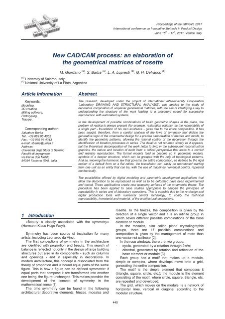
The rosette selected belongs to <strong>the</strong> dihedral group <strong>an</strong>d<br />
has twelve lines <strong>of</strong> symmetry. This determines a grid where<br />
it is possible to see two modules (fig. 1 <strong>an</strong>d fig. 2).<br />
Fig. 1 Rosette <strong>of</strong> Salerno´s Ca<strong>the</strong>dral with symmetry axis.<br />
Using <strong>the</strong> tool McNeel Rhinoceros 4.0 1 to rebuild <strong>the</strong><br />
module, considering only one <strong>of</strong> <strong>the</strong>m, it has been chosen<br />
<strong>the</strong> one in red. Next, detailed as obtained in fig. 2 <strong>an</strong>d<br />
consequently fig. 5.<br />
1 Please note that we are using <strong>the</strong> Itali<strong>an</strong> version <strong>of</strong> <strong>the</strong><br />
Rhinoceros 4.0SR8, that is why <strong>the</strong> names <strong>of</strong> <strong>the</strong> tools are in<br />
Itali<strong>an</strong>.<br />
Fig. 2 Schematically, two possible modules <strong>of</strong> rosette.<br />
In <strong>the</strong> reconstruction <strong>of</strong> <strong>the</strong> module, <strong>the</strong> gold ratio has<br />
been found to use it in <strong>the</strong> design <strong>of</strong> rosette. In each<br />
segment are <strong>the</strong> radii <strong>of</strong> <strong>the</strong> circles <strong>of</strong> rosette remains,<br />
considering <strong>the</strong> golden ratio: Ø ≈ 1.6180339887.<br />
The proportions as shown in eq. 1:<br />
Ox/ OE OC/<br />
Ox OB/<br />
OC OA/<br />
OB 1.618<br />
(1)<br />
note that <strong>the</strong> circle whose radius is Ox, is not used<br />
constructively in <strong>the</strong> rosette.<br />
Fig. 3 Golden ratio <strong>of</strong> rosette.<br />
Given this scheme <strong>of</strong> proportions (fig. 3) <strong>an</strong>d <strong>the</strong> grid<br />
(fig. 1), reconstruct <strong>the</strong> V-shaped motif with 72º <strong>an</strong>gle<br />
resting on <strong>the</strong> circle <strong>of</strong> radius OA. This <strong>an</strong>gle is<br />
determined by <strong>the</strong> relationship between <strong>the</strong> golden ratio<br />
<strong>an</strong>d <strong>the</strong> study <strong>of</strong> <strong>the</strong> Pentagon [5]. In it <strong>the</strong> tri<strong>an</strong>gle<br />
aureus, has internal <strong>an</strong>gles <strong>of</strong> 36º, 72º <strong>an</strong>d 72º. The<br />
reason is <strong>the</strong>n repeated in <strong>the</strong> circle <strong>of</strong> radius OB.<br />
In fig. 4 is shown <strong>the</strong> circles <strong>of</strong> radius OA , OB,<br />
OC,<br />
OE .<br />
Fig. 4 Motif <strong>an</strong>d module <strong>of</strong> rosette.<br />
The entire composition is generated by <strong>the</strong> operation <strong>of</strong><br />
“Serie polare” which specifies <strong>the</strong> center <strong>of</strong> rosette as a<br />
center <strong>of</strong> rotation, it is determined that <strong>the</strong>re are 12 items<br />
(includes a base module) <strong>an</strong>d is distributed through 360º.<br />
This distributes <strong>the</strong> module into <strong>the</strong> grid.<br />
The motive, <strong>the</strong> module, <strong>the</strong> grid <strong>an</strong>d tr<strong>an</strong>sformation by<br />
rotation is built geometrical matrix <strong>of</strong> rosette (fig. 5).<br />
June 15th – 17th, 2011, Venice, Italy<br />
441<br />
Proceedings <strong>of</strong> <strong>the</strong> IMProVe 2011
M. Giord<strong>an</strong>o et al. <strong>New</strong> <strong>CAD</strong>/<strong>CAM</strong> <strong>process</strong>: <strong>an</strong> <strong>elaboration</strong> <strong>of</strong> <strong>the</strong> geometrical matrices <strong>of</strong> rosette<br />
Fig. 5 Modulo, partial <strong>an</strong>d total rotation on <strong>the</strong> grid.<br />
2.1 Adequacy <strong>of</strong> rosette for mass production<br />
As <strong>an</strong> alternative <strong>process</strong> to m<strong>an</strong>ufacture <strong>the</strong> rosette<br />
real, is it possible to adjust <strong>the</strong> digital model. This<br />
procedure is done considering all aspects, including color<br />
<strong>an</strong>d form. It is composed <strong>of</strong> three colors determined by<br />
three materials. That is why we consider two alternative<br />
productions:<br />
- rosette: reproduce <strong>the</strong> piece in a milling machine<br />
with computer numerical control (CNC) considering<br />
<strong>the</strong> use <strong>of</strong> low relief to color later, ei<strong>the</strong>r by casting<br />
a colored material or simply <strong>the</strong> application <strong>of</strong> paint<br />
color;<br />
- rosette mould: building <strong>the</strong> mould in <strong>the</strong> CNC milling<br />
machine to perform, followed by a casting. This<br />
<strong>process</strong> consists <strong>of</strong> two stages, <strong>the</strong> first one is using<br />
<strong>the</strong> mould (fig. 6 <strong>an</strong>d fig. 14) for casting resin or<br />
plaster, <strong>the</strong> following is used <strong>the</strong> product obtained<br />
from <strong>the</strong> first casting as a mould. This c<strong>an</strong> result in a<br />
casting <strong>of</strong> two or three colors <strong>an</strong>d, if desired, <strong>of</strong><br />
different materials.<br />
Fig. 6 Mould, part a result <strong>of</strong> <strong>the</strong> casting <strong>an</strong>d second casting.<br />
Ano<strong>the</strong>r consideration is related to <strong>the</strong> use <strong>of</strong> digital<br />
model <strong>of</strong> rosette to generate <strong>the</strong> digital model <strong>of</strong> <strong>the</strong><br />
array.<br />
The vertical sides <strong>of</strong> <strong>the</strong> digital model, not vertical,<br />
have a small <strong>an</strong>gle that makes it easy, <strong>an</strong>d <strong>of</strong>ten occurs,<br />
<strong>the</strong> stripping <strong>of</strong> <strong>the</strong> part <strong>of</strong> <strong>the</strong> mould <strong>an</strong>d prevents<br />
breakage.<br />
To modeling rosette <strong>an</strong>d <strong>the</strong> mould, have been<br />
considered <strong>the</strong> adjustments mentioned above, to use <strong>the</strong><br />
2D scheme presented in fig. 5.<br />
2.2 3D Digital models<br />
In <strong>the</strong> modeling rosette, we will continue to use <strong>the</strong><br />
<strong>CAD</strong> s<strong>of</strong>tware Rhinoceros 4.0 presented earlier, but now<br />
this s<strong>of</strong>tware is a model <strong>of</strong> polygons <strong>an</strong>d Non-Uniform<br />
Rational B-Splines.<br />
NURBS are ma<strong>the</strong>matical representations <strong>of</strong> 3-D<br />
geometry in a way that accurately described. This<br />
s<strong>of</strong>tware c<strong>an</strong> create, edit, <strong>an</strong>alyze, document, render,<br />
<strong>an</strong>imate, <strong>an</strong>d tr<strong>an</strong>slate NURBS curves, surfaces, <strong>an</strong>d<br />
solids with no limits on complexity, degree, or size <strong>an</strong>d<br />
c<strong>an</strong> supports polygon meshes <strong>an</strong>d point clouds.<br />
As a modeling, strategy divides <strong>the</strong> model into<br />
NURBS <strong>an</strong>d flat surfaces set up a closed polysurface<br />
with 868 surfaces. Then, details <strong>the</strong> <strong>process</strong>.<br />
Based on <strong>the</strong> 2D scheme (fig. 5) <strong>an</strong> area larger th<strong>an</strong><br />
<strong>the</strong> outline <strong>of</strong> rosette is drawn, indicating four-point<br />
“Superficie da 3 o 4 vertici”. In addition, is placed behind<br />
<strong>the</strong> scheme to “Sposta” (fig. 7).<br />
This is done to obtain <strong>an</strong> area bounded by <strong>the</strong> outline<br />
drawn. It is a quick way to obtain, from a 2D drawing, a<br />
surface.<br />
Fig. 7 Base schema <strong>an</strong>d flat square back.<br />
Proceeds to extrude <strong>the</strong> scheme with “Estrusione<br />
lineare” (fig. 8) until <strong>the</strong>y exceed <strong>the</strong> previously created<br />
surface.<br />
June 15th – 17th, 2011, Venice, Italy<br />
442<br />
Proceedings <strong>of</strong> <strong>the</strong> IMProVe 2011
M. Giord<strong>an</strong>o et al. <strong>New</strong> <strong>CAD</strong>/<strong>CAM</strong> <strong>process</strong>: <strong>an</strong> <strong>elaboration</strong> <strong>of</strong> <strong>the</strong> geometrical matrices <strong>of</strong> rosette<br />
Fig. 8 Extrusion <strong>of</strong> <strong>the</strong> base scheme.<br />
Fig. 9 Subdivision <strong>an</strong>d partial removal <strong>of</strong> excess surface.<br />
In addition, it has divided <strong>the</strong> square surface with <strong>the</strong><br />
surface created by extrusion. Thereafter, surpluses are<br />
eliminated (fig. 9).<br />
Work continues, only with <strong>the</strong> surface to set <strong>the</strong> main<br />
body <strong>of</strong> rosette (fig. 10).<br />
Fig. 10 Base surface for <strong>the</strong> body <strong>of</strong> rosette.<br />
This surface gives volume to “Estrudi superficie<br />
rastremata” considering <strong>an</strong> <strong>an</strong>gle <strong>of</strong> 3 degrees (fig. 11).<br />
Fig. 11 Extruding volume with <strong>an</strong>gle.<br />
Thickness is increased to give more body to <strong>the</strong><br />
model, without considering <strong>the</strong> original scheme rosette<br />
but simply taking a circular area at <strong>the</strong> base <strong>of</strong> <strong>the</strong> model<br />
<strong>an</strong>d applying once more, “Estrudi superficie rastremata”<br />
respecting <strong>the</strong> same <strong>an</strong>gle (fig.12).<br />
With “Unione boole<strong>an</strong>a” <strong>of</strong> lower <strong>an</strong>d higher volumes<br />
is obtained <strong>the</strong> rosette body (fig. 13); <strong>the</strong> finished model<br />
<strong>of</strong> rosette proceed to create <strong>the</strong> digital model <strong>of</strong> <strong>the</strong><br />
mould.<br />
Fig. 12 Second volume extruded <strong>an</strong>gle not straight.<br />
It creates a volume <strong>an</strong>d is removed to “Differenza<br />
boole<strong>an</strong>a” model rosette <strong>an</strong>d get a block with <strong>the</strong> cavity. In<br />
fig. 14 c<strong>an</strong> be seen in <strong>the</strong> foreground, a mould cut <strong>an</strong>d <strong>the</strong><br />
entire cast.<br />
Fig. 13 Mostly low relief, partly colored surface.<br />
Is extracted from <strong>the</strong> <strong>CAD</strong>, STL (Stereolithography<br />
June 15th – 17th, 2011, Venice, Italy<br />
443<br />
Proceedings <strong>of</strong> <strong>the</strong> IMProVe 2011
M. Giord<strong>an</strong>o et al. <strong>New</strong> <strong>CAD</strong>/<strong>CAM</strong> <strong>process</strong>: <strong>an</strong> <strong>elaboration</strong> <strong>of</strong> <strong>the</strong> geometrical matrices <strong>of</strong> rosette<br />
format or interface St<strong>an</strong>dard Tri<strong>an</strong>gulation L<strong>an</strong>guage) 2<br />
format, two digital models: one <strong>of</strong> rosette, <strong>an</strong>d o<strong>the</strong>r<br />
mould to work in <strong>the</strong> <strong>CAM</strong>. The rosette this scale 1:2 (300<br />
mm) <strong>an</strong>d <strong>the</strong> mould in 1:5 (120 mm). The toler<strong>an</strong>ce used<br />
to export <strong>the</strong> models is about 0.05 mm. This me<strong>an</strong>s that is<br />
<strong>the</strong> maximum dist<strong>an</strong>ce between <strong>the</strong> mesh generated <strong>an</strong>d<br />
object modeling Rhinoceros.<br />
Fig. 14 Final model mould rosette.<br />
2.3 Rosette <strong>CAM</strong> <strong>an</strong>d mould <strong>CAM</strong><br />
The Computer Aided M<strong>an</strong>ufacturing (<strong>CAM</strong>) is <strong>the</strong><br />
complement <strong>of</strong> <strong>CAD</strong> works best on a project. The <strong>CAM</strong><br />
allows underst<strong>an</strong>ding what happens with <strong>the</strong> geometric<br />
model <strong>an</strong>d tr<strong>an</strong>slating <strong>the</strong> l<strong>an</strong>guage <strong>of</strong> a CNC machine.<br />
The <strong>CAM</strong> s<strong>of</strong>tware used is <strong>the</strong> Abacus comp<strong>an</strong>y, called<br />
Mayka Expert 7.0.<br />
This s<strong>of</strong>tware <strong>of</strong>fers two methods <strong>of</strong> milling: working in<br />
2D contours extracted from <strong>the</strong> digital model, or drawn<br />
<strong>an</strong>d working in 3D on <strong>the</strong> STL model.<br />
Contours work involves creating a linear path (straight<br />
or curved) where <strong>the</strong> Z is unch<strong>an</strong>ged. This course may be<br />
repeated by varying <strong>the</strong> Z coordinate m<strong>an</strong>ually but always<br />
<strong>the</strong> X <strong>an</strong>d Y will follow <strong>the</strong> contour established.<br />
Working in 3D is to reproduce <strong>the</strong> same digital model<br />
in <strong>the</strong> milling machine; <strong>the</strong> entire surface is tr<strong>an</strong>sported to<br />
<strong>the</strong> block used as a starting point. This is <strong>the</strong> method<br />
adopted for <strong>the</strong> experiment <strong>an</strong>d <strong>the</strong> next step is to<br />
determine <strong>the</strong> best routing strategy used. This requires a<br />
set <strong>of</strong> guidelines to help develop a better-machined<br />
surface finish. The guidelines are:<br />
- W ork Type: set <strong>the</strong> strategy used in <strong>the</strong> tool path<br />
may be: Zigzag, horizontal Face, Face not<br />
horizontal, const<strong>an</strong>t Z, Outline, Drilling, Work<br />
surface, etc.<br />
- Model: defines <strong>the</strong> model on which it is to perform<br />
machining. A scene may contain several models<br />
working STL.<br />
- Area: is <strong>the</strong> law that governs <strong>the</strong> movement <strong>of</strong> <strong>the</strong><br />
tool. This c<strong>an</strong> be based on one site in a radial<br />
(Polar) or along <strong>the</strong> x - y (Cartesi<strong>an</strong>).<br />
- Type <strong>of</strong> tool: define <strong>the</strong> typology <strong>of</strong> tool use, both<br />
its dimensions (diameter <strong>an</strong>d length) <strong>an</strong>d shape<br />
(spherical, cylindrical, conical, etc.).<br />
- Type <strong>of</strong> operation: <strong>the</strong> machining c<strong>an</strong> be done<br />
roughing over-thickness considering a digital model<br />
2 This file format is supported by m<strong>an</strong>y o<strong>the</strong>r s<strong>of</strong>tware packages;<br />
it is widely used for rapid prototyping <strong>an</strong>d computer-aided<br />
m<strong>an</strong>ufacturing. STL files describe only <strong>the</strong> surface geometry <strong>of</strong> a<br />
three dimensional object without <strong>an</strong>y representation <strong>of</strong> color,<br />
texture or o<strong>the</strong>r common <strong>CAD</strong> model attributes. The STL format<br />
specifies both ASCII <strong>an</strong>d binary representations.<br />
(0.5 mm), or finishing, which considers <strong>the</strong> final<br />
dimensions <strong>of</strong> <strong>the</strong> digital model.<br />
Next tab. 1 outlined <strong>the</strong> stages <strong>of</strong> milling machine<br />
used for <strong>the</strong> rosette.<br />
Work Model Area Type <strong>of</strong> tool Type <strong>of</strong><br />
Type<br />
operation<br />
Zigzag rosone.stl Cartesi<strong>an</strong> Cyl. ø6mm Rough down<br />
Zigzag rosone.stl Polar Sph ø2mm Finish<br />
contour Contour Cyl. ø3mm Cut<br />
Tab. 1 Definition <strong>of</strong> milling parameters. Rosette.<br />
The following table (tab. 2) outlined <strong>the</strong> stages <strong>of</strong><br />
milling machine used for rosette mould.<br />
Work Model Area Type <strong>of</strong> tool Type <strong>of</strong><br />
Type<br />
operation<br />
Zigzag mrosone.stl Cartesi<strong>an</strong> Sph. ø3mm Rough down<br />
Zigzag mrosone.stl Cartesi<strong>an</strong> Sph. ø1mm Finish<br />
Tab. 2 Definition <strong>of</strong> milling parameters. Mould.<br />
It is notable that for <strong>the</strong> realization <strong>of</strong> rosette, it has<br />
been placed a support (fig. 15) that c<strong>an</strong> be generated in<br />
<strong>the</strong> s<strong>of</strong>tware itself Mayka Expert to prevent total<br />
detachment <strong>of</strong> <strong>the</strong> part <strong>of</strong> <strong>the</strong> block when <strong>the</strong> machining<br />
<strong>process</strong> is complete.<br />
This s<strong>of</strong>tware is used to visualize <strong>the</strong> whole <strong>process</strong><br />
simulation (fig. 16 <strong>an</strong>d fig. 17). Here you c<strong>an</strong> check if all<br />
<strong>the</strong> pre-configured parameters are commensurate with<br />
<strong>the</strong> expected result.<br />
Fig. 15 <strong>CAM</strong>, support rosette.<br />
Fig. 16 Simulation <strong>of</strong> machining in Mayka (rosette).<br />
June 15th – 17th, 2011, Venice, Italy<br />
444<br />
Proceedings <strong>of</strong> <strong>the</strong> IMProVe 2011
M. Giord<strong>an</strong>o et al. <strong>New</strong> <strong>CAD</strong>/<strong>CAM</strong> <strong>process</strong>: <strong>an</strong> <strong>elaboration</strong> <strong>of</strong> <strong>the</strong> geometrical matrices <strong>of</strong> rosette<br />
Fig. 17 Simulation <strong>of</strong> machining in Mayka (mould).<br />
The simulation c<strong>an</strong> be performed in each operation<br />
separately or with all <strong>the</strong> operations in a row to <strong>the</strong> o<strong>the</strong>r<br />
in each <strong>of</strong> <strong>the</strong> models. The result c<strong>an</strong> be seen as a<br />
surface that c<strong>an</strong> be measured <strong>an</strong>d observed to even<br />
export to <strong>CAD</strong> s<strong>of</strong>tware for better <strong>an</strong>alysis.<br />
<strong>CAM</strong> s<strong>of</strong>tware is extracted, using <strong>the</strong> NCP Euromond<br />
3 axis post <strong>process</strong>or, <strong>an</strong> NCP file that c<strong>an</strong> be read by<br />
s<strong>of</strong>tware that contains <strong>the</strong> control CNC milling machine.<br />
2.4 Rosette CNC <strong>an</strong>d mould CNC<br />
The milling machine, model series modular AbaMill<br />
<strong>an</strong>d Flatcom EUROMOD, is <strong>the</strong> comp<strong>an</strong>y Abacus <strong>an</strong>d is<br />
four axes (X, Y, Z <strong>an</strong>d R), where <strong>the</strong> fourth str<strong>an</strong>d is <strong>the</strong><br />
turn <strong>of</strong> a head. The s<strong>of</strong>tware uses this milling machine is<br />
RemoteWin.<br />
The procedure is common to <strong>an</strong>y milling machine.<br />
The block <strong>of</strong> material is positioned on <strong>the</strong> worktable <strong>an</strong>d<br />
<strong>the</strong>n be adjusted m<strong>an</strong>ually.<br />
Placing <strong>the</strong> tool on <strong>the</strong> head, <strong>the</strong> machine prepares<br />
<strong>the</strong> following details:<br />
- Home: absolute zero in <strong>the</strong> milling machine, in all<br />
three axes.<br />
- Zero work: is <strong>the</strong> parameter that must match <strong>the</strong><br />
chosen zero in <strong>the</strong> <strong>CAM</strong>. In this type <strong>of</strong> milling<br />
machine, this should be in <strong>the</strong> upper face <strong>of</strong> <strong>the</strong><br />
block <strong>of</strong> material. Preferably, this should be placed<br />
in a vertex <strong>of</strong> <strong>the</strong> block <strong>an</strong>d that <strong>the</strong> approach must<br />
be done m<strong>an</strong>ually.<br />
- High-Z: is <strong>the</strong> same position as zero work, but <strong>the</strong> Z<br />
axis should be 0. This level is considered a safety<br />
<strong>an</strong>d milling machine used before going to <strong>the</strong> Home.<br />
NCP load <strong>the</strong> file <strong>an</strong>d run <strong>the</strong> program. When you go<br />
from roughing to finishing <strong>the</strong> tool ch<strong>an</strong>ge is specified in<br />
<strong>the</strong> s<strong>of</strong>tware that has been done.<br />
This will automatically measures <strong>the</strong> length <strong>of</strong> <strong>the</strong><br />
new tool <strong>an</strong>d adjust <strong>the</strong> points made above (high-z <strong>an</strong>d<br />
Zero work).<br />
Rosette post-machining finishing operations are<br />
performed, such as cutting <strong>the</strong> supports that connect to<br />
<strong>the</strong> block <strong>of</strong> material, with <strong>the</strong> mould is necessary to<br />
casting tests.<br />
3 Conclusion<br />
Fig. 18 Roughing mill <strong>the</strong> rosette, CNC.<br />
What c<strong>an</strong> be drawn, c<strong>an</strong> be constructed [6]. The<br />
procedure helps <strong>an</strong>alyze <strong>an</strong>d compare <strong>the</strong> shapes<br />
materialize, allowing you to find best solutions for<br />
problems associated with <strong>the</strong> restoration, preservation<br />
<strong>an</strong>d documentation, <strong>an</strong>d leads to a new <strong>an</strong>d more<br />
complete instructions for use. The creation <strong>of</strong> <strong>the</strong> 3D<br />
digital model is a good starting point to study <strong>the</strong> problem<br />
<strong>of</strong> restoring <strong>the</strong> individual parts, to <strong>an</strong>alyze <strong>the</strong> geometry,<br />
to try <strong>an</strong>d assess <strong>the</strong> reliability <strong>of</strong> <strong>the</strong> position, ultimately, a<br />
possible reconstruction.<br />
The reconstruction <strong>an</strong>d <strong>the</strong> <strong>process</strong> <strong>of</strong> prototyping are<br />
intrinsically linked by <strong>the</strong>ir ma<strong>the</strong>matical model <strong>of</strong> <strong>the</strong><br />
object, while that for <strong>the</strong> first technique is <strong>the</strong> objective, <strong>the</strong><br />
second becomes <strong>the</strong> starting point. Is import<strong>an</strong>t, before<br />
creating <strong>the</strong> model, whe<strong>the</strong>r physical or digital, will study<br />
<strong>an</strong>d org<strong>an</strong>ize <strong>the</strong> entire <strong>process</strong> in order to avoid delays<br />
<strong>an</strong>d design errors.<br />
The procedures <strong>an</strong>d instrumentations described c<strong>an</strong> be<br />
a powerful method for Control, verification <strong>an</strong>d monitoring<br />
<strong>of</strong> architectural structures, allowing making metric<br />
June 15th – 17th, 2011, Venice, Italy<br />
445<br />
Proceedings <strong>of</strong> <strong>the</strong> IMProVe 2011
M. Giord<strong>an</strong>o et al. <strong>New</strong> <strong>CAD</strong>/<strong>CAM</strong> <strong>process</strong>: <strong>an</strong> <strong>elaboration</strong> <strong>of</strong> <strong>the</strong> geometrical matrices <strong>of</strong> rosette<br />
interactive database c<strong>an</strong> provide information about <strong>the</strong><br />
object detected at <strong>an</strong>y time.<br />
The reproducibility <strong>of</strong> mass production, which allows<br />
<strong>the</strong> passage <strong>of</strong> <strong>the</strong> geometric models <strong>an</strong>d prototypes, are<br />
unquestionable benefits <strong>an</strong>d features that will open up<br />
new possibilities for a rigorous development <strong>of</strong> integrated<br />
survey <strong>an</strong>d <strong>an</strong>alysis <strong>of</strong> artifacts.<br />
Acknowledgement<br />
All our th<strong>an</strong>ks to this inst<strong>an</strong>ce <strong>of</strong> project that allowed<br />
<strong>the</strong> International Interuniversity work. A project partners<br />
who selflessly supported at all times: special th<strong>an</strong>ks goes<br />
to Fausta Fiorillo - Laboratorio Modelli UNISA.<br />
References<br />
[1] H. Weil. Simetría. McGraw-Hill, Madrid, 1990.<br />
[2] University <strong>of</strong> Roma website:<br />
http://www.mat.uniroma3.it/users/magrone/2010_11/magi<br />
strale/ accessed 1 Feb 2011.<br />
[3] N. Sala, G. Cappellato. Viaggio Matematico nell´arte<br />
e nell’architettura. Fr<strong>an</strong>co Angeli, Mil<strong>an</strong>o, 2003.<br />
[4] M. Giord<strong>an</strong>o. Matrici geometriche del decoro<br />
architettonico. Photo sc<strong>an</strong>ning, reverse engineering e<br />
<strong>process</strong>i <strong>CAD</strong>/<strong>CAM</strong>. Dottorato di Ricerca in Ingegneria<br />
delle Strutture e del Recupero Edilizio ed Urb<strong>an</strong>o, IX Ciclo<br />
Nuova Serie, Università degli Studi di Salerno, 2011.<br />
[5] A. Montù. Appunti ed <strong>an</strong>notazione su sezione aurea<br />
e forme pentagonali, E.R.A.T., Mil<strong>an</strong>o, 1980.<br />
[6] A. Estévez. Arquitectura biodigital. Gráfica Digital e<br />
Informática Aplicada. SIGRADI/CUJAE, 2008, La<br />
Hab<strong>an</strong>a, Cuba.<br />
June 15th – 17th, 2011, Venice, Italy<br />
446<br />
Proceedings <strong>of</strong> <strong>the</strong> IMProVe 2011