Improving Helicopter Flight Simulation with Rotor ... - IMProVe2011
Improving Helicopter Flight Simulation with Rotor ... - IMProVe2011
Improving Helicopter Flight Simulation with Rotor ... - IMProVe2011

Create successful ePaper yourself
Turn your PDF publications into a flip-book with our unique Google optimized e-Paper software.
636<br />
Proceedings of the IMProVe 2011<br />
International conference on Innovative Methods in Product Design<br />
June 15 th – 17 th , 2011, Venice, Italy<br />
<strong>Improving</strong> <strong>Helicopter</strong> <strong>Flight</strong> <strong>Simulation</strong> <strong>with</strong> <strong>Rotor</strong> Vibrations<br />
(a) University of Bologna, DIEM Department<br />
Article Information<br />
Keywords:<br />
<strong>Simulation</strong>,<br />
Computer Aided Design,<br />
Design Methodology,<br />
Vibrations,<br />
Finite Element Analysis.<br />
Corresponding author:<br />
Alessandro Ceruti<br />
Tel.:+39 051 2093452<br />
Fax.:+39 051 2093412<br />
e-mail: alessandro.ceruti@unibo.it<br />
Address: University of Bologna,<br />
Department of Mechanical, Nuclear,<br />
Aeronautical Engineering and<br />
Metallurgy.<br />
1 Introduction<br />
1.1 State of the art<br />
A.Ceruti (a) , A. Liverani (a) , L., Recanatesi (a)<br />
Abstract<br />
Modern engineering exploits the capabilities of<br />
simulation both for design purposes, both for training.<br />
Software packages of Finite Element Analysis (FEM) and<br />
Computational Fluid Dynamics (CFD) are useful tools to<br />
simulate the behavior of a body when stressed by a load<br />
or when immersed into a fluid. The simulation applications<br />
to training concerns for example driving, flying, traffic and<br />
queue, manufacturing and robot motion. Virtual Reality [1]<br />
has been also used to support simulation realism [2], both<br />
in immersive, and in un-immersive systems. The research<br />
in simulation issues focuses the attention not only on the<br />
dynamic models (which compute the behaviour of the<br />
phenomena to simulate), but also on visualization<br />
systems. Head Mounted Display (HMD) [3], large field of<br />
view cluster of projectors, hemispherical monitors are<br />
widely used to increase simulation realism [4]. Problems<br />
like image blending have been solved using algorithm<br />
producing a better overlapping of image sides common to<br />
two or more projectors. Also techniques of geometry<br />
correction has been developed to correct the image<br />
distortion on flat or round screens. Virtual environments<br />
[5] like CAVE for stereo projection and 3D visualization<br />
has been developed and applied to simulation. Also the<br />
use of sounds is wide spread in simulator. But view and<br />
hearing are only two of human five senses: sight, hearing,<br />
touch, smell and taste. Modern simulators try to exploits<br />
also the other senses to improve the simulation. Devices<br />
dealing <strong>with</strong> touch are called “haptic”; an example of<br />
these is force feedback on simulators commands. A<br />
classical application of simulation is the helicopter flight<br />
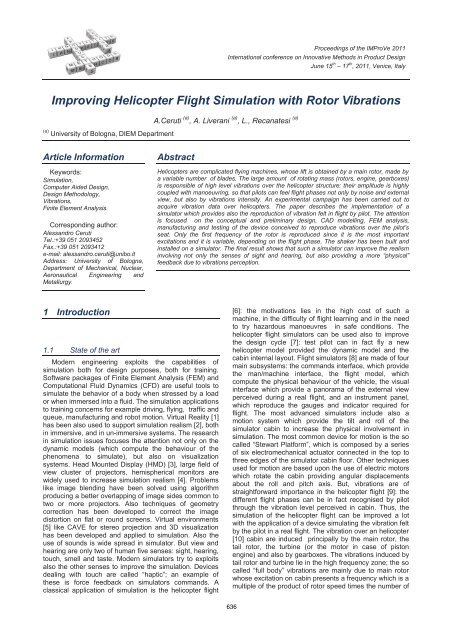
<strong>Helicopter</strong>s are complicated flying machines, whose lift is obtained by a main rotor, made by<br />
a variable number of blades. The large amount of rotating mass (rotors, engine, gearboxes)<br />
is responsible of high level vibrations over the helicopter structure: their amplitude is highly<br />
coupled <strong>with</strong> manoeuvring, so that pilots can feel flight phases not only by noise and external<br />
view, but also by vibrations intensity. An experimental campaign has been carried out to<br />
acquire vibration data over helicopters. The paper describes the implementation of a<br />
simulator which provides also the reproduction of vibration felt in flight by pilot. The attention<br />
is focused on the conceptual and preliminary design, CAD modelling, FEM analysis,<br />
manufacturing and testing of the device conceived to reproduce vibrations over the pilot’s<br />
seat. Only the first frequency of the rotor is reproduced since it is the most important<br />
excitations and it is variable, depending on the flight phase. The shaker has been built and<br />
installed on a simulator. The final result shows that such a simulator can improve the realism<br />
involving not only the senses of sight and hearing, but also providing a more “physical”<br />
feedback due to vibrations perception.<br />
[6]: the motivations lies in the high cost of such a<br />
machine, in the difficulty of flight learning and in the need<br />
to try hazardous manoeuvres in safe conditions. The<br />
helicopter flight simulators can be used also to improve<br />
the design cycle [7]: test pilot can in fact fly a new<br />
helicopter model provided the dynamic model and the<br />
cabin internal layout. <strong>Flight</strong> simulators [8] are made of four<br />
main subsystems: the commands interface, which provide<br />
the man/machine interface, the flight model, which<br />
compute the physical behaviour of the vehicle, the visual<br />
interface which provide a panorama of the external view<br />
perceived during a real flight, and an instrument panel,<br />
which reproduce the gauges and indicator required for<br />
flight. The most advanced simulators include also a<br />
motion system which provide the tilt and roll of the<br />
simulator cabin to increase the physical involvement in<br />
simulation. The most common device for motion is the so<br />
called “Stewart Platform”, which is composed by a series<br />
of six electromechanical actuator connected in the top to<br />
three edges of the simulator cabin floor. Other techniques<br />
used for motion are based upon the use of electric motors<br />
which rotate the cabin providing angular displacements<br />
about the roll and pitch axis. But, vibrations are of<br />
straightforward importance in the helicopter flight [9]: the<br />
different flight phases can be in fact recognised by pilot<br />
through the vibration level perceived in cabin. Thus, the<br />
simulation of the helicopter flight can be improved a lot<br />
<strong>with</strong> the application of a device simulating the vibration felt<br />
by the pilot in a real flight. The vibration over an helicopter<br />
[10] cabin are induced principally by the main rotor, the<br />
tail rotor, the turbine (or the motor in case of piston<br />
engine) and also by gearboxes. The vibrations induced by<br />
tail rotor and turbine lie in the high frequency zone; the so<br />
called “full body” vibrations are mainly due to main rotor<br />
whose excitation on cabin presents a frequency which is a<br />
multiple of the product of rotor speed times the number of
A.Ceruti et al. <strong>Improving</strong> <strong>Helicopter</strong> <strong>Flight</strong> <strong>Simulation</strong> <strong>with</strong> <strong>Rotor</strong> Vibrations<br />
blades. In the last few times the market started to offer a<br />
series of devices for vibration simulation. The frequency<br />
of waves generated [11] is usually between 0 and 40 Hz,<br />
while the maximum amplitude is of few millimeters.<br />
1.2 This Paper<br />
This paper describes the conceptual design, the<br />
dimensioning, the CAD modelling, the FEM analysis, the<br />
final manufacturing and assembly of a device useful to<br />
simulate helicopter rotor vibration. The design started<br />
from an experimental phase in which the vibrations<br />
recorded onboard a full scale helicopter have been<br />
collected and analysed in the whole flight envelope. The<br />
analysis of the collected data and of helicopters<br />
specifications taken form bibliography, provided a better<br />
understanding of the vibration phenomena and of its<br />
perception by pilots and passengers. The device design<br />
has been carried out applying the classical formulas of<br />
machine dynamics and mechanical dimensioning. The<br />
device has been finally added to an helicopter flight<br />
simulator developed at the Bologna University. Results<br />
obtained show the correct ending of the project and<br />
confirm the design methodology effectiveness.<br />
In the next second paragraph of the paper, the design<br />
methodology is described; the third section contains a<br />
brief introduction to the problem of vibrations in helicopter<br />
and describes the experimental phase of in-flight vibration<br />
data collecting. A brief list of the University of Bologna<br />
helicopter simulator main features is presented in the<br />
fourth section; the product design cycle of the shaker is<br />
reported in the fifth section, starting from conceptual<br />
design up to the installation; a conclusion paragraph<br />
highlights the project results, the advantages in realism<br />
gained and the drawback of the adopted solution.<br />
2 Design Methodology<br />
The design methodology followed for this work is<br />
represented in fig. 1, where all of the phases are listed.<br />
One of the most important design phase is the<br />
determination of the frequency and accelerations<br />
amplitudes range of interest. The simulator should in fact<br />
reproduce the vibrations perceived on board a large part<br />
of helicopters. The smallest helicopter are ultralight<br />
machines, <strong>with</strong>out sophisticated devices for vibration<br />
suppression; on the other side, large helicopters present<br />
a better rotor mechanics, high power turbine (or turbines),<br />
takeoff mass up to thousands of Kilograms. One of the<br />
design requirements is so the modularity, as to gain the<br />
possibility to simulate not only one model of helicopter,<br />
but a large class of machines. It is very important to study<br />
the vibrating phenomena over several helicopters so to<br />
cover the most significant vibrations which can be found<br />
in the frequency domain.<br />
This kind of research has been performed using a<br />
powerful mathematical operation called ‘Fourier<br />
Transform’ (described in the next paragraph), which allow<br />
to split a generic time domain signal into the sum of many<br />
different fundamental signals, each carrying a different<br />
single oscillation frequency.<br />
<strong>Helicopter</strong> <strong>Flight</strong><br />
Data Collection Data Processing<br />
Shaker conceptual<br />
design<br />
CAD modelling<br />
FEM analysis<br />
Prototype Construction<br />
Device<br />
Installation/Integration<br />
System Test<br />
Fig. 1: Design phases diagram<br />
Once the vibration amplitudes and frequencies have<br />
been investigated, the conceptual design of the device<br />
can start. Many solutions for vibrations reproduction have<br />
been considered, comparing technical capacity and<br />
drawbacks. The most promising solution have been<br />
deeply analysed in a more detailed design: after a first<br />
rough dimensioning, the device has been modelled <strong>with</strong>in<br />
a CAD environment. In the following a series of FEM<br />
analysis has been deployed to check the design<br />
robustness. The virtual model of the shaker system has<br />
been added to a 3D model of the simulator to verify the<br />
installation and the interface <strong>with</strong> the simulator frame. The<br />
follow-up work has been the manufacturing of a prototype<br />
and its installation on the simulator. A final phase of<br />
testing concludes the design workflow.<br />
3 Vibrations on helicopters<br />
Frequency/<br />
Amplitude<br />
field of<br />
interest<br />
There are different important sources of vibration on<br />
board of an helicopter: They can be in general grouped<br />
into three main categories:<br />
- Main <strong>Rotor</strong> (shaft and blades) induced vibrations;<br />
- Engine and relative gearboxes vibrations;<br />
- Tail <strong>Rotor</strong> (shaft and blades) induced vibrations.<br />
Each of these mechanical groups contain a<br />
considerable amount of moving masses which rotate at a<br />
significant angular speed: main rotor speed is typically<br />
between 300 RPM for large helicopters, up to 600 RPM<br />
for ultralight helicopters. The turbine rotational velocity<br />
can be up to tens thousand of RPM, depending on turbine<br />
diameters. Tail rotor speed is normally a multiple of main<br />
rotor speed, since a rigid mechanical transmission<br />
synchronize the two rotors. Normal rates of transmission<br />
are variable between 4 to 7, depending on the tail rotor<br />
June 15th – 17th, 2011, Venice, Italy<br />
637<br />
Proceedings of the IMProVe 2011
A.Ceruti et al. <strong>Improving</strong> <strong>Helicopter</strong> <strong>Flight</strong> <strong>Simulation</strong> <strong>with</strong> <strong>Rotor</strong> Vibrations<br />
diameter and helicopter’s features. Following this<br />
consideration, it’s immediate to understand that all these<br />
rotating masses can easily introduce very high level<br />
amplitude vibration phenomena on the entire helicopter<br />
structure. The main rotor vibrations [12] are mainly due to<br />
an asymmetric distribution of the unsteady aerodynamic<br />
forces on the blades: the exciting frequency lies in the<br />
range 12-40 Hz, depending on number of blades and<br />
rotor shaft rounds per minuteIn order to better evaluate<br />
the entity of this kind of vibrations, an experimental<br />
campaign has been carried on. A triaxial accelerometer<br />
has been rigidly mounted inside the helicopter fuselage<br />
(Fig. 2) of a series of helicopters. Using this sensor, it has<br />
been possible to collect vibration data during different<br />
typical helicopter flight phases like ‘Hovering Out of<br />
Ground Effect’ (HOGE), ‘Hovering In Ground Effect’<br />
(HIGE), climb, descent, and cruise at various speeds. The<br />
test equipment employed for vibration measures is made<br />
by: a triaxial accelerometer (+-5 g), a Signal Acquisition<br />
Module (<strong>with</strong> a sampling frequency up to 50kHz, 24 bit of<br />
resolution) and a PC for data storing and synchronizing.<br />
Fig. 1: Accelerometer positioned inside the helicopter cabin<br />
Fig. 2: Acceleration signal sample, measured about the<br />
vertical axis (‘z’)<br />
It’s not possible to identify the characteristic<br />
frequencies of the helicopter used for the test from the<br />
acquired acceleration signal, as can be seen from Fig. 3.<br />
The use of a mathematical operator is necessary to<br />
transport the time-domain measured signals in the<br />
frequency domain: this operator is called the Fourier<br />
Transform. Practically, this operation splits a single time<br />
varying signal in a sum of contributes, each one at a<br />
different frequency.<br />
The transformation calculated is not a continuous<br />
signal integration, but an optimized approximation called<br />
Fast Fourier Transform (or ‘FFT’): a saving in<br />
computational resources is gained by this way.<br />
Figure 3 shows the analysis of a Fourier transform of<br />
the Z axis acceleration for frequencies up to 1000 Hz:<br />
main rotor, tail rotor and turbine contributions can be<br />
easily found.<br />
Fig. 4: FFT of the vertical vibrations measured at<br />
maximum speed, frequency [0-1000 Hz].<br />
Focusing the attention on the first 100 Hz of the<br />
vibration spectrum, the fundamental frequencies of the<br />
main rotor can be found. The main rotor speed is in fact<br />
380 RPM, so the corresponding frequency is about 6.36<br />
Hz; the number of blades is 2. The harmonic main rotor<br />
frequencies will be so:<br />
k<br />
f k N f _ k N RPM / 60 k N / rev<br />
k 1,2... n<br />
<br />
rotor rotor shaft shaft<br />
Where:<br />
Number of blades (N): 2<br />
Main rotor shaft speed (RPMshaft) in RPM: 382 RPM<br />
Main rotot shaft speed (1/rev) in Hz: 6.37<br />
Harmonic frequency order (k): 1,2,3<br />
It follows (for the first 4 harmonics):<br />
1 2 3 4<br />
f 12.7 ; f 25.5 ; f 38.1; f 50.8<br />
rotor rotor rotor rotor<br />
The speed of the main rotor is normally kept constant by a<br />
regulator but the amplitude of the vibrations are highly<br />
dependent of the flight phase. Figures 3, 4, 5 highlight the<br />
difference in amplitudes between the phases of Hovering<br />
Out of Ground Effect (in which the rotor aerodynamic and<br />
the air flow is quite regular), the flight at cruise speed (for<br />
which the vibration suppression system has been<br />
designed), and the flight at maximum speed (VNE) phase.<br />
In this helicopter the 1-N/rev amplitude is lower than the<br />
2-N/rev and 3-N/rev because of in commercial helicopter<br />
damping systems are installed to reduce the vibrations in<br />
the low frequencies which are well felt by the human<br />
body.<br />
Fig. 3: FFT of the vertical vibration measured during ‘HOGE’<br />
phase (amplitude vs frequency [Hz])<br />
June 15th – 17th, 2011, Venice, Italy<br />
638<br />
Proceedings of the IMProVe 2011
A.Ceruti et al. <strong>Improving</strong> <strong>Helicopter</strong> <strong>Flight</strong> <strong>Simulation</strong> <strong>with</strong> <strong>Rotor</strong> Vibrations<br />
Fig. 4: FFT of the vertical vibration measured during a<br />
100 KTS cruise (amplitude vs frequency [Hz])<br />
Fig. 5: FFT of the vertical vibration measured at the VNE<br />
(amplitude vs frequency [Hz])<br />
As it can be seen from the above figures, is clearly<br />
visible that the amplitude peaks are positioned at the<br />
expected frequencies. Furthermore, the amplitude of the<br />
vibrations induced by main rotor is variable <strong>with</strong> flight<br />
phase. Results obtained are in agreement <strong>with</strong><br />
bibliographic data, as Figure 6 and 7 taken from<br />
Bibliography [13], [14], [15] shows. Figure 7 in particular<br />
show the amplitude of vibration of the 4 blade German<br />
helicopter BO 105 as a function of the speed.<br />
Fig. 6: FFT of the BO 105 helicopter in level cruise flight<br />
(Source: O. Dietrich [13] and T. Mannchen[14])<br />
Fig. 7: BO 105 Vibration amplitude <strong>with</strong> speed (Source:<br />
Strehlow et al. [15] and T. Mannchen [14])<br />
The above concerns will drive the design of the device for<br />
the vibrations reproductions. In particular two are the<br />
main issues to consider:<br />
- The rotor speed is constant: the first harmonics<br />
can lie in the interval [10-30] Hz, mainly depending on the<br />
number of blades since the rotation speed is about 400-<br />
600 RPM for all the conventional helicopters.<br />
- The amplitude of the vibrations is variable<br />
depending on the flight phase, from a minimum of 0.01 to<br />
a maximum of 0.15 g, which correspond to 0.1 m/s 2 and<br />
1.5 m/s 2 .<br />
3.1 Vibrations and human body<br />
The body perception of vibrations is mainly due to the<br />
resonance of the internal organs, which is about [16]:<br />
- 7-19 Hz for eyes and head<br />
- 3-5 Hz for heart<br />
- 3-6 Hz for internal organs like liver, spleen, kidney<br />
- 5-12 Hz for spinal column<br />
Furthermore, vibration can be divided in<br />
- “full-body” (industrial machines, air ground and<br />
marine transports, normally passing through feet or seat),<br />
- “hand arm” (Industrial pneumatic and electric tools<br />
hand held, like drill or hammer drill).<br />
Full-body accelerations [17] presents medium-low<br />
frequencies (2-20 Hz) and involves the whole body;<br />
frequency at higher frequency are felt only locally by skin.<br />
<strong>Helicopter</strong>s <strong>with</strong>out vibration compensation systems,<br />
and helicopters <strong>with</strong> small weight presents a peak of<br />
vibrations amplitude for the 1-N/rev frequency.<br />
The most critical vibrations [18] for the human body lie<br />
in the range 4-6 Hz, as the international norm ISO-2631<br />
[19] explains; the interpretation of graphs of iso-exposition<br />
to vibrations shows how a vibration of 6 Hz and 0.3 m/s 2<br />
RMS amplitude can be sustained for 8 hours. The same<br />
value of exposition is prescribed for a vibration of 2.5 m/s 2<br />
(which is 8 time greater) at 60 Hz.<br />
As a conclusion, the most critical frequency in<br />
helicopter flight (<strong>with</strong> reference to body behaviour) seems<br />
to be the first N/rev. This frequency is not so far from the<br />
critical 4-6 Hz range. The other N/rev harmonics, even if in<br />
certain cases (large helicopters <strong>with</strong> vibration suppression<br />
devices) present larger acceleration amplitude, seems to<br />
be less “felt” by the human body.<br />
4 <strong>Helicopter</strong> <strong>Flight</strong> Simulator layout<br />
The Bologna University flight simulator is made up of a<br />
cluster of 3 PC connected <strong>with</strong> a local net providing:<br />
dynamics computation, external visual representation,<br />
flight commands acquisition. The implementation of the<br />
vibration simulation required to dedicate a PC to this task;<br />
the simulation speed is not affected by this new device<br />
since the other two PC are not overcharged. The main<br />
PC1 is connected to the helicopter simulator flight<br />
commands (collective, rudder, cyclic) by a USB port so<br />
that all the commands excursions are acquired in real<br />
time. The flight commands are in fact endowed <strong>with</strong><br />
potentiometer sensors so that each displacement can be<br />
acquired using a dedicated acquisition module, and then<br />
used directly in the simulation program.<br />
A mathematical model of the flight is implemented in<br />
the PC 1. Different helicopter models can be simulated:<br />
the mathematical model is parametric so that new<br />
helicopter model data can be loaded each simulation run.<br />
Position (Lat Long Alt), attitude (Pitch Roll an Yaw), speed<br />
and accelerations are sent to the PC2. The PC 2 provides<br />
the visualization of the external view (based on the free<br />
simulator <strong>Flight</strong>gear) and of the instrument panel. A<br />
second UDP connection links PC1 <strong>with</strong> PC3.<br />
June 15th – 17th, 2011, Venice, Italy<br />
639<br />
Proceedings of the IMProVe 2011
A.Ceruti et al. <strong>Improving</strong> <strong>Helicopter</strong> <strong>Flight</strong> <strong>Simulation</strong> <strong>with</strong> <strong>Rotor</strong> Vibrations<br />
Fig. 8: <strong>Helicopter</strong> Simulator Layout<br />
The mathematical model implemented for the helicopter<br />
dynamics [20] has been taken from books [21], reports<br />
and journal papers. The following Figure 9 shows the<br />
simulator view taken from the pilot seat.<br />
Fig. 9: UniBo helicopter simulator external view and flight<br />
5 Shaker design<br />
instruments panel<br />
The shaker design has been carried out following four<br />
steps: the conceptual design, the dimensioning, the CAD<br />
modeling, the FEM analysis. As presented in the previous<br />
sections, vibrations over helicopters cover a large<br />
spectrum of frequencies. But the most important ones are<br />
the medium/low frequencies. It is assumed that the<br />
shaker will reproduce only the amplitude of the first<br />
frequency of the rotor. This is a strong simplification which<br />
can be justified by the following matters:<br />
- the contemporary reproduction of more than one<br />
frequency requires expensive tools and a complicated<br />
control system.<br />
- the amplitude of the accelerations at the first rotor<br />
frequency of the rotor vary <strong>with</strong> the flight phase.<br />
- the frequencies of gearboxes and turbine are<br />
typically high and stress the structure; but are well over<br />
the resonance of the human organs.<br />
- the first rotor frequency depends on the rotor shaft<br />
speed and on the number of blades (which are data<br />
available for all helicopters), and the amplitude can be<br />
guess comparing data of similar helicopter. By this way,<br />
an approximate simulation can be performed also <strong>with</strong>out<br />
experimental data of the helicopter.<br />
5.1 Shaker conceptual design and layout<br />
The main requirements for the shaker are maximum<br />
acceleration peak and frequency; the second is a fixed<br />
value once defined the helicopter model, while the<br />
acceleration peak should vary during the flight depending<br />
on the flight phase. The possible shaker solutions which<br />
were considered for the helicopter simulator application,<br />
have been taken from bibliography [22] and by technical<br />
solutions widely spread in mechanics like:<br />
1. Shaker <strong>with</strong> fixed eccentric mass and vibration<br />
intensity regulation through elastic elements<br />
deformation;<br />
2. Shaker <strong>with</strong> magnetic eccentric;<br />
3. Shaker <strong>with</strong> crank shaft mechanism to change<br />
vibration intensity;<br />
4. Shaker <strong>with</strong> eccentric variable through cam<br />
profile shape;<br />
5. Shaker <strong>with</strong> ‘Watt’ type variable eccentric.<br />
6. Electrodynamic shaker<br />
7. Hydraulic shaker<br />
8. Pneumatic shaker<br />
The best technical solution selection process was<br />
performed considering the following parameters:<br />
Technical complexity of electrical and electronics<br />
boards and devices needed for the regulation of<br />
the vibrations amplitude;<br />
Mechanical realization complexity;<br />
Weight of the system;<br />
Integration capability <strong>with</strong>in the simulator frame<br />
and structure (small dimensions);<br />
Shape of the produced vibrations;<br />
Final cost;<br />
Adaptability to a widest range of vibration<br />
frequency and amplitudes.<br />
At the end of the evaluation process, the Watt type<br />
variable eccentric device was preferred since it seemed to<br />
be a low cost solution able to satisfy the requirements.<br />
The device is made by two eccentric masses linked by<br />
two counter-rotating shafts, moved by an electric motor;<br />
The eccentricity of the rotating masses is changed by a<br />
stepper motor which acts on a maneuvering screw (see<br />
also Fig.21). By this way, moving back and forth the<br />
shaker regulator slider different values of eccentricity can<br />
be obtained.<br />
The eccentric can be equilibrated as to obtain low<br />
unbalance; this can be useful in high speed rotating<br />
rotors, for which a small eccentric mass is required. On<br />
the contrary, the maximum amplitude of vibrations can be<br />
increased by adding a larger mass.<br />
The following Figure 10 present a conceptual study of<br />
the eccentric device: in green the electric motor, in red the<br />
max volume occupied by eccentric mechanism, frame in<br />
white and green. The shaker in fact is made up by an<br />
electric motor, two counter rotating masses and a frame.<br />
The frame is required to connect the motor and the<br />
eccentric mechanism; at the top a series of screws rigidly<br />
connect the frame <strong>with</strong> the seat. The whole system frame<br />
and seat are suspended over the simulator frame by a<br />
series of springs. These springs can also be replaced in a<br />
short time, permitting to simulate non standard helicopters<br />
behaviors.<br />
June 15th – 17th, 2011, Venice, Italy<br />
640<br />
Proceedings of the IMProVe 2011
A.Ceruti et al. <strong>Improving</strong> <strong>Helicopter</strong> <strong>Flight</strong> <strong>Simulation</strong> <strong>with</strong> <strong>Rotor</strong> Vibrations<br />
Fig. 10: Conceptual layout of the shaker: motor (green),<br />
eccentric maximum volume (red), frame (white and grey).<br />
5.2 Shaker dimensioning<br />
The equation describing the motion of a system<br />
excited by an harmonic force is:<br />
Mx cx kx F F(<br />
t)<br />
(1)<br />
Where:<br />
M: mass of the system<br />
C: damping<br />
k: stiffness<br />
F(t): exciting force<br />
The shaker can be schematized as a vibrodyne: it is a<br />
mechanical system made by two counter-rotating masses<br />
<strong>with</strong> a given eccentricity respect to the rotation axis. The<br />
Figure 11 presents two masses (m1; m2) <strong>with</strong> an opposite<br />
rotational speed (Ω; -Ω), and <strong>with</strong> the same eccentricity<br />
(e).<br />
Fig. 11: Vibrodyne scheme<br />
The centrifugal force acting on the masses are Fc1 and<br />
Fc2, defined as:<br />
Fc1 m e(<br />
)<br />
2<br />
1 ;<br />
Fc2 m e(<br />
)<br />
2<br />
2 (2)<br />
But the forces Fc1 and Fc2 can be decomposed on the<br />
axis x and y of Figure 13, so that:<br />
June 15th – 17th, 2011, Venice, Italy<br />
641<br />
Proceedings of the IMProVe 2011<br />
<br />
2<br />
Fc1_ x m1e( ) cos t<br />
<br />
2<br />
Fc1_ y m1e( ) sin( t)<br />
<br />
2<br />
Fc2 _ x m2e( ) cos t<br />
<br />
2<br />
Fc2 _ y m2e( ) sin( t)<br />
Summing the contributions of the mass 1 and 2 in<br />
direction of the x and y axis it follows:<br />
2 2<br />
Fctotal x m1e( ) cos( t) m2e( ) cos( t)<br />
<br />
2 2<br />
Fctotal y m1e( ) sin( t) m2e( ) sin( t)<br />
If m1= m2 and if a new variable m is defined as m=m1+<br />
m2 it follows:<br />
Fctotal x 0<br />
<br />
Fctotal<br />
y me t<br />
2<br />
( ) sin( )<br />
The shaker dynamic equation will then be<br />
approximated to a single degree of freedom vibration,<br />
where x represent the vertical translation of the system:<br />
2<br />
Mx cx kx me<br />
sin( t)<br />
(7)<br />
This equation can be solved (after an initial transient) in<br />
terms of displacement x, as:<br />
x <br />
2 me / k sin t <br />
<br />
<br />
<br />
2<br />
2<br />
2<br />
2<br />
n n<br />
<br />
1 / 2 / <br />
<br />
Where:<br />
k / M ; c / 2m<br />
n n<br />
The dimensions required for the design of the shaker is<br />
the product of eccentric mass per eccentricity and the<br />
spring stiffness; the requirements are the whole system<br />
maximum acceleration (in terms of [g] or [m/s 2 ]) and a<br />
(3)<br />
(4)<br />
(5)<br />
(6)<br />
(8)
A.Ceruti et al. <strong>Improving</strong> <strong>Helicopter</strong> <strong>Flight</strong> <strong>Simulation</strong> <strong>with</strong> <strong>Rotor</strong> Vibrations<br />
rotating frequency (the N/rev, in [Hz]). The unknown<br />
quantities can be found by solving the equation (7) and<br />
(8) or by a simplified methodology, valid only for a rough<br />
estimation of the mass per eccentricity product in early<br />
design purposes.<br />
In this simplified approach the stiffness and the<br />
damping of the system are neglected, so that the motion<br />
equation became:<br />
2<br />
Mx me me<br />
sin( t)<br />
(9)<br />
Ordering the terms it follows:<br />
me<br />
2<br />
x <br />
sin( t)<br />
M Which can be recognized as an harmonic dynamics of<br />
the type:<br />
x x <br />
(10)<br />
2<br />
x x sin( t)<br />
By the comparison of the equations (9) and (10) it<br />
follows:<br />
2<br />
x max x max max , xmax m e / M<br />
(11)<br />
Now considering that the maximum acceleration and<br />
the rotational speed are known, the maximum<br />
displacement x can be found. The product mass per<br />
eccentricity is then expressed like:<br />
2<br />
max max /<br />
m e M x M xmax<br />
2 / max / M x (12)<br />
max<br />
The spring stiffness can be computed by the formula of<br />
the displacement in mass-spring forced system:<br />
x<br />
<br />
me<br />
2<br />
K M<br />
<br />
max 2<br />
(13)<br />
The only unknown is the stiffness of the spring, while<br />
other terms are known.<br />
As an example, <strong>with</strong> mass M=150 Kg, 1-N/rev=13 Hz<br />
and max acceleration equal to 0.5 m/s2, we have:<br />
2<br />
m e 150 0.5 / (2 pi 13) 0.01Kg<br />
m<br />
which can be obtained for instance using two eccentric<br />
masses of 50 grams, and an eccentricity of 100 mm.<br />
The stiffness of the spring in this case will be:<br />
K=990000 N/m,<br />
And <strong>with</strong> 4 springs in parallel, the stiffness of each one<br />
will result:<br />
K=250 N/mm, which represent a deflection of 1 mm<br />
<strong>with</strong> a force of 25o N.<br />
An helical spring <strong>with</strong> a 3mm wire diameter presents<br />
similar values.<br />
5.3 CAD modelling<br />
All the shaker parts have been modeled <strong>with</strong>in a 3D<br />
CAD, as Figure 12 shows.<br />
June 15th – 17th, 2011, Venice, Italy<br />
642<br />
Proceedings of the IMProVe 2011<br />
.<br />
Fig. 12: CAD modeling of the shaker, <strong>with</strong> its eccentric<br />
masses<br />
All the parts of the 3D model has been assembled and<br />
coded <strong>with</strong> labels to allow the further assembly, as Figure<br />
13 shows.<br />
Fig. 13: Assembly drawing of the shaker<br />
A series of 2D drawings have been realized to product<br />
parts. Materials used to build the device are: steel, nylon,<br />
aluminum.<br />
Fig. 14: 2D constructive drawing of one of the shaker<br />
components<br />
Also the frame of the shaker has been modeled as<br />
Figure 15 shows.
A.Ceruti et al. <strong>Improving</strong> <strong>Helicopter</strong> <strong>Flight</strong> <strong>Simulation</strong> <strong>with</strong> <strong>Rotor</strong> Vibrations<br />
Fig.15: 3D model of the shaker frame<br />
5.4 FEM analysis<br />
A Finite Element analysis was required to check<br />
dynamic interference between the simulator frame and<br />
the shaker frame. The software used is Patran for<br />
preprocessing and post-processing, and Nastran as the<br />
main solver. For instance, the model of the shaker<br />
support structure has been modeled <strong>with</strong>in the Patran<br />
software: mono-dimensional ‘beam’ type elements have<br />
been applied to simulate all of the metal tubes and<br />
sections in the structure. A single concentrated ‘mass<br />
element’ positioned on the motor CoG and joined to the<br />
support plate through ‘rigid elements’ has been used to<br />
model the motor itself. The complete model is made of<br />
422 nodes and 458 elements, for a total of 2261 degrees<br />
of freedom (DOF). Element types used in the model are:<br />
Beam, Plate, Mass, Rigid.<br />
Beam elements are used to represent tubes and bars,<br />
<strong>with</strong> the following dimensions: “L” type beam dimension<br />
50x50x5 mm, Plain beam of 40x5 mm, Plain beam of<br />
50x8 mm, Plain beam of 55x10 mm, Plain beam of 50x10<br />
mm, Square beam of 40x40x5 mm, Bar <strong>with</strong> a diameter of<br />
D=20 mm.<br />
The material used in the FEM modeling process is<br />
carpentry steel which has been chosen for cost and for<br />
weldability. Its main characteristics are:<br />
- Young Modulus: 2.1 e11 N/mm 2<br />
- Poisson coefficient: 0.29<br />
- Density: 7850 Kg/m3<br />
- Max design Tension: 200 N/m 2<br />
The model (Fig. 16) constraints consist in 4 joints<br />
(each of them blocking all 6 degrees of freedom)<br />
positioned in the upper part of the structure, at the<br />
connection between the seat and the simulator.<br />
Fig. 16: FEM model of the frame and shaker<br />
The natural vibration modes have been found to be:<br />
- Mode 1 : 49 Hz<br />
- Mode 2 : 64 Hz<br />
- Mode 3 : 78 Hz<br />
- Mode 4 : 146 Hz<br />
Among all these modes, the most interesting are those<br />
presenting a deformed which agrees <strong>with</strong> the direction of<br />
the shaker harmonic excitation force, because they can<br />
be subject to resonance.<br />
Fig. 17: First (left) vibration mode: 49 Hz; fourth (right)<br />
vibration mode: 146 Hz<br />
Following these considerations, the shaker support<br />
structure modes which have a practical interest are the<br />
first one at 49 Hz and the fourth at 146 Hz, which are<br />
beyond the work frequency of the device. A similar<br />
investigation has been performed for the simulator frame.<br />
5.5 Electric Motor<br />
The electric motor needed to move the eccentric<br />
mechanism has been selected considering a maximum<br />
frequency for the first harmonic of 40 Hz. The torque of<br />
the motor is not a mandatory requirement since the only<br />
reaction is given by the friction of the bearings. Transitory<br />
dynamic is not so fast; the changes in amplitude of<br />
vibrations are small due to the inertia of the helicopter,<br />
which speeds up and decelerates in quite long times.<br />
The characteristic of the motor (in Figure 18) are:<br />
- maximum power output = 550 Watt;<br />
- single phase, bipolar electric motor;<br />
- max angular speed of 2440 RPM<br />
- endowed <strong>with</strong> an inverter for speed settings.<br />
Fig. 18: Electric motor and inverter to set the rotation speed.<br />
The stepper motor is small enough to fit into the<br />
assembly: the torque required is very low and the correct<br />
angular position is provided by a look-up table which sets<br />
the number of motor steps needed to move the screw in<br />
order to obtain the desired eccentricity. A control board is<br />
linked to PC3, which drives the stepper motor and<br />
computes (in open chain loop) the current and required<br />
June 15th – 17th, 2011, Venice, Italy<br />
643<br />
Proceedings of the IMProVe 2011
A.Ceruti et al. <strong>Improving</strong> <strong>Helicopter</strong> <strong>Flight</strong> <strong>Simulation</strong> <strong>with</strong> <strong>Rotor</strong> Vibrations<br />
position of the eccentricity. A calibration procedure is<br />
necessary to set the correct initialization of the control<br />
system.<br />
Fig. 19: Stepper motor: CAD and real<br />
5.6 Manufacturing and assembly<br />
All the parts have been designed and manufactured<br />
aiming to lower the costs. The chosen materials are<br />
aluminium for non structural parts to be machined; nylon<br />
for non structural parts to be worked by lathe; steel for<br />
structural parts. Moreover, a large use of commercial<br />
items has been considered for bearings, screws, springs.<br />
The following Figure 20 shows the work in progress of<br />
bearings covers and support plates.<br />
Fig.20: Manufacturing process of the shaker radial<br />
bearing enclosures by automatic machine<br />
In the following Figure 21, there are some picture of<br />
CAD and realized parts.<br />
Fig. 21: View of the shaker eccentricity regulator (down) and<br />
housing for bearings (up) CAD model (left) and after<br />
manufacturing (right)<br />
Finally, the shaker has been assembled and installed<br />
in the simulator, as Figure 22 shows.<br />
Fig. 22: Image of the shaker frame (bottom part <strong>with</strong> shaker<br />
and motor- left) and upper part (connected to the seat-right)<br />
The assembly seat / shaker has been suspended on<br />
the simulator frame by four helical springs.<br />
Fig. 23 Shaker group (seat+frame+motor, in the left)<br />
suspended on simulator frame by springs (in the right).<br />
6 Final Result<br />
The following Figure 24 presents a CAD image of the<br />
device installed on the simulator structure.<br />
Figure 24: 3D CAD view of the simulator<br />
The simulator has been evaluated by an operator both<br />
in static mode, and <strong>with</strong> vibration shaker on, returning a<br />
realistic feeling. In spite of the lack of higher frequency<br />
replication, the simulator has been successfully tested by<br />
several pilots <strong>with</strong> positive comments in terms of realism.<br />
June 15th – 17th, 2011, Venice, Italy<br />
644<br />
Proceedings of the IMProVe 2011
A.Ceruti et al. <strong>Improving</strong> <strong>Helicopter</strong> <strong>Flight</strong> <strong>Simulation</strong> <strong>with</strong> <strong>Rotor</strong> Vibrations<br />
Fig. 25: Simulator <strong>with</strong> shaker turned on (right) and off (left)<br />
7 Conclusion<br />
This work presents the workflow of a design activity<br />
which led to the implementation of a device to be used in<br />
helicopter flight simulators to reproduce flight vibrations.<br />
<strong>Helicopter</strong> pilot is in fact accustomed to feel different<br />
levels of vibrations during flight, depending on flight<br />
phases. The largest part of current simulator is not<br />
provided <strong>with</strong> such a device owing to high cost and<br />
complication of electrodynamic shakers.<br />
A device useful to reproduce the first frequency of the<br />
main rotor has been so designed and tested.<br />
The design of the device started by the analysis of the<br />
typical frequencies felt inside the cabin during the whole<br />
flight envelope. Next, the data has been analyzed as to<br />
define a list of requirements. A conceptual design phase<br />
led to the definition of the shaker configuration; a 3D<br />
modeling and a further FEM analysis campaign was<br />
performed in the detail design phase. The manufacturing<br />
and the assembly of the device allowed the installation of<br />
the device over an helicopter simulator. The whole<br />
system have been implemented and tested: the<br />
reproduction of vibration increases the similarity <strong>with</strong> real<br />
flight and contribute to the realism of the simulation.<br />
Acknowledgement<br />
Authors wish to thank University of Bologna<br />
engineering students (II Faculty of Engineering,<br />
Mechanical and Aerospace Courses) and technical<br />
personnel which contributed to the realization of the<br />
shaker and of the simulator.<br />
References<br />
[1] H. Tamura, H. Yamamoto and A. Katayama, Mixed<br />
reality: future dreams seen at the border between real<br />
and virtual worlds, IEEE Computer Graphics and<br />
Applications, 2001, pp.64-70.<br />
[2] Y. Yin, X. Sun, X. Zhang, X. Liu, H. Ren, X. Zhang<br />
and Y. Jin, Application of Virtual Reality in Marine Search<br />
and Rescue Simulator, The International Journal of Virtual<br />
Reality, 2010, 9(3): pp19-26.<br />
[3] S.P. Rogers, Evaluation of earth-fixed HMD symbols<br />
using the PRISMS helicopter flight simulator; (Anacapa<br />
Sci. Inc., Santa Barbara, CA, USA); Asbury, C.N.;<br />
Haworth, L.A. Source: Proceedings of the SPIE - The<br />
International Society for Optical Engineering, v 3689, p<br />
54-65, 1999.<br />
[4] S.P. Rogers, C.N. Asbury, and L.A. Haworth,<br />
Development of a powerful but inexpensive helicopter<br />
flight simulator.<br />
[5] S.P., Rogers, and C.N. Asbury, Development of a<br />
flight simulator and an intelligent symbology management<br />
system for helmet mounted displays in rotorcraft, Santa<br />
Barbara, CA: Anacapa Sciences, Inc., 1999.<br />
[6] M., Baarspul, A review of flight simulation techniques,<br />
Prog. Aerospace Sci., vol.27, pp.1-120, 1990.<br />
[7] M.L., Preatoni, A., Ragazzi, A., Ceruti, G. M.,,<br />
Saggiani, <strong>Flight</strong> Mechanics Simulator for <strong>Rotor</strong>craft<br />
Development, ICAS 2008, 26TH International Congress of<br />
the Aeronautical Sciences.<br />
[8] European Aviation Safety Agency “Authority and<br />
Organisation Requirements”, Certification Specifications<br />
for <strong>Helicopter</strong> <strong>Flight</strong> <strong>Simulation</strong> Training Devices<br />
CSFSTD(H), 2008.<br />
[9] S.R., Viswamurthy, R. Ganguli, Modeling and<br />
compensation of piezoceramic actuator hysteresis for<br />
helicopter vibration control, Sensors and Actuators, A:<br />
Physical, v 135, n 2, p 801-810, April.<br />
[10] Taikang Ning Fu-Shang Wei, Multichannel coherence<br />
analysis of helicopter vibrations, ICSP'02. 2002 6th<br />
International Conference on Signal Processing<br />
Proceedings p 1774-7 vol.2, 2002.<br />
[11] Wittenstein company website. http://www.wittensteinus.com/news/VIBE-seat-shaker.cfm,<br />
accessed on<br />
February 7, 2011.<br />
[12] R. Bielawa, Rotary Wing Structural Dynamics and<br />
Aeroelasticity, AIAA Education Series, American Institute<br />
of Aeronautics and Astronautics, 1992.<br />
[13] O., Dieterich, Application of Modern Control<br />
Technology for Advanced IBC Systems, 24th European<br />
<strong>Rotor</strong>craft Forum, Marseilles, 1998.<br />
[14] T. Mannchen, <strong>Helicopter</strong> Vibration Reduction Using<br />
Robust Control, Thesis - Institut für Flugmechanik und<br />
Flugregelung, Universität Stuttgart 2003 - bo 105 report<br />
da cui ho tratto tutto.<br />
[15] H. Strehlow, R. Mehlhose, P. Znika, Passive and<br />
Active Vibration Control Activities in the German<br />
<strong>Helicopter</strong> Industry, Aero Tech 92 Conference,<br />
Birmingham, 1992<br />
[16] F. Gobbato, Medicina del lavoro, Elsevier 2002.<br />
[17] C. Gomes de Oliveira, D. M. Simpson, J. Nadala,<br />
Lumbar back muscle activity of helicopter pilots and<br />
whole-body vibration, Journal of Biomechanics Volume<br />
34, Issue 10 , October 2001, Pages 1309-1315, Elsevier<br />
Science Ltd.<br />
[18] E. Tomao, F. De Nuntiis, Le Vibrazioni Meccaniche:<br />
effetti sull'uomo, XXII Giornata Romana di Medicina del<br />
Lavoro "Antonello Spinazzola", 6 Maggio 2006.<br />
[19] International Standard Organization, ISO 2631<br />
Mechanical Vibrations, 1997.<br />
[20] G. D., Padfield, <strong>Helicopter</strong> <strong>Flight</strong> Dynamics: The<br />
Theory and Application of Flying Qualities and <strong>Simulation</strong><br />
Modelling, AIAA Education Series, 1996.<br />
[21] A. R. Bramwell, <strong>Helicopter</strong> Dynamics, Butterworth-<br />
Heinemann, ISBN 0-7506-5075-3, 2001.<br />
[22] D. Cambiaghi, S. Soldà, E. Chirone, V. Villa, Studio e<br />
progettazione di un dispositivo meccanico per eseguire<br />
prove di vibrazione ad ampiezza regolabile, Proceedings<br />
of the ADM Conference, 2005.<br />
June 15th – 17th, 2011, Venice, Italy<br />
645<br />
Proceedings of the IMProVe 2011