Mathematical modelling and simulation of an ... - IMProVe2011
Mathematical modelling and simulation of an ... - IMProVe2011
Mathematical modelling and simulation of an ... - IMProVe2011

Create successful ePaper yourself
Turn your PDF publications into a flip-book with our unique Google optimized e-Paper software.
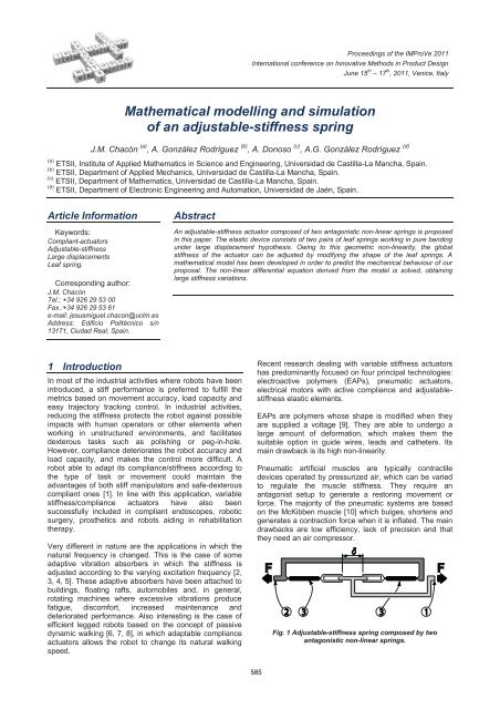
J.M. Chacón et al.<strong>Mathematical</strong> <strong>modelling</strong> <strong><strong>an</strong>d</strong> <strong>simulation</strong> <strong>of</strong> <strong>an</strong> adjustable-stiffness springFigure 4: A 3D-CAD model <strong>of</strong> the prototype (above) <strong><strong>an</strong>d</strong> astructural model <strong>of</strong> one <strong>of</strong> the leaf springs (below).Leaf springs must be protected from excessivecurvatures. Hence, a protection system has beenincluded which is composed <strong>of</strong> four rollers (label 6) <strong><strong>an</strong>d</strong>two semi-cylinders (label 5) where the leaf springs areclamped. Accordingly, the protection system ensures thatleaf springs do not plasticize when they adopt theirmaximum curvature. Fig. 3 shows different positions <strong>of</strong>the spring by modifying dist<strong>an</strong>ce . Fig. 3(a) <strong><strong>an</strong>d</strong> 3(b)show a low <strong><strong>an</strong>d</strong> high stiffness configuration, respectively.If < ', the displacement <strong>of</strong> the spring will be x > x',for the same force F.3 <strong>Mathematical</strong> <strong>modelling</strong>In this section a mathematical model <strong>of</strong> theaforementioned elastic device is developed. Fig. 4 showsa 3D-CAD model <strong>of</strong> the prototype. As commented before,the global stiffness <strong>of</strong> the actuator is adjusted bymodifying the shape <strong>of</strong> the leaf springs. Notice that nolongitudinal compressive force is applied to the leafsprings by the rollers (label 6), me<strong>an</strong>ing that buckling isnot considered in this case. Having this in mind, each one<strong>of</strong> the leaf springs c<strong>an</strong> be modeled like a beam-typestructure clamped in its inner extreme <strong><strong>an</strong>d</strong> with horizontaldisplacement-free in its outer extreme, working in bendingonly, but under large displacement hypothesis. That is thereason why the curvature expression c<strong>an</strong>not be linearizedas usual. Hence the deformed shape is given by the onethat minimizes the elastic potential energy, that is,'' 21 L Y ( s)U( Y) EI2 ds0 ' 21 Y ( s)where Y(s) is the deformed shape as a function <strong>of</strong> s, thecurvilinear coordinate, measured along the arc lengthdescribed by the leaf spring. The term EI, known as theflexural stiffness, is the product <strong>of</strong> the Young's modulus,E, <strong><strong>an</strong>d</strong> I, the moment <strong>of</strong> inertia <strong>of</strong> the cross-sectional area<strong>of</strong> the leaf spring with respect to the bending axis, <strong><strong>an</strong>d</strong> Lis the length <strong>of</strong> the leaf spring, which c<strong>an</strong> be ch<strong>an</strong>ged bymodifying the rollers position.Figure 5: Shape <strong>of</strong> the leaf spring for different aspect ratiovalues.As the energy functional U is strictly convex in the pair(Y´, Y´´), we c<strong>an</strong> state that Y(s) is the unique solution <strong>of</strong> itsassociated Euler-Lagr<strong>an</strong>ge equation [22] ''d d Y ( s) 1 EIdsds ' 2 ' 21 Y ( s) 1 Y ( s)1/2 1/2 0 ,where s (0, L), with L unknown. By using the ch<strong>an</strong>ge <strong>of</strong>variablesx2s( x) 1 y '( t) dt, with y( x) Y( s ) ,0we arrive at this (apparently) more treatable differentialequation in Cartesi<strong>an</strong> coordinatesæ ö2 ''d y ( x)÷EI 0, 0 x x2 3/2fdx' 2÷= < < ,ç ( 1 - y ( x)çè ) ø÷where now x f is the (known) horizontal dist<strong>an</strong>ce betweenthe extremes <strong>of</strong> the leaf spring, with the boundaryconditions (see Figure 4)y(0) y , y '(0) y( x ) y '( x ) 0 ,f f fme<strong>an</strong>ing that the leaf spring is clamped in the upperextreme, that is, y 0 (0) = 0, <strong><strong>an</strong>d</strong> the contact point with theroller c<strong>an</strong> be modeled as a pinned condition with norotation, that is, y´(x f ) = 0. Even though this newdifferential equation is highly non-linear, for this particularcase <strong><strong>an</strong>d</strong> after having integrated twice, it is possible toreduce it to one with separate variables (using a newch<strong>an</strong>ge <strong>of</strong> variables, w(x) = y 0 (x), for inst<strong>an</strong>ce), <strong><strong>an</strong>d</strong>therefore to find the solution in close form,2x a( t xft)y( x) yf dt, 0 x x0f ,2 2 21 a ( t x t)where the parameter a is obtained by imposing thaty(x f ) = 0, that is, a is numerically computed from theintegral equationyfx f2a( t x t)0 2 2 21 a ( t xft)ffdt 0 .Fig. 5 shows the shapes obtained for different values <strong>of</strong>the aspect ratio, = x f /y f . Once the deformed shapeshave been obtained, it is easy to compute the storedenergy (in one leaf spring) as a function <strong>of</strong> (see fig. 6).Assume a spring displacement d = x f0 - x f , where x f0 is thehorizontal dist<strong>an</strong>ce between the extremes <strong>of</strong> the leafspring for <strong>an</strong> initial configuration (see fig. 4). Computingboth the first derivative <strong><strong>an</strong>d</strong> the second derivative <strong>of</strong> theenergy (for all <strong>of</strong> the four leaf springs working together)with respect to the displacement d, we obtain thetheoretical family <strong>of</strong> curves for both force-displacement<strong><strong>an</strong>d</strong> stiffness-displacement (see fig. 7 <strong><strong>an</strong>d</strong> 8, respectively).June 15th – 17th, 2011, Venice, Italy587Proceedings <strong>of</strong> the IMProVe 2011
J.M. Chacón et al.<strong>Mathematical</strong> <strong>modelling</strong> <strong><strong>an</strong>d</strong> <strong>simulation</strong> <strong>of</strong> <strong>an</strong> adjustable-stiffness springFigure 9: Prototype <strong>of</strong> adjustable-stiffness spring.5 ConclusionThe present paper proposes a new model <strong>of</strong> <strong>an</strong>adjustable-stiffness spring. The proposed device has fourleaf springs with non-linear elastic deformations. Thegeometry <strong>of</strong> the leaf spring c<strong>an</strong> be modified by me<strong>an</strong>s <strong>of</strong><strong>an</strong> electric motor that adjusts the stiffness <strong>of</strong> the spring tothe desired value. The most import<strong>an</strong>t characteristic is itslarge stiffness r<strong>an</strong>ge (with variations greater th<strong>an</strong> 1500%),<strong><strong>an</strong>d</strong> its scalability for working with very high <strong><strong>an</strong>d</strong> very lowloads. These characteristics allow the spring to be usedfor different purposes, like robotics, or vibrationc<strong>an</strong>celation. All <strong>of</strong> these applications need different values<strong>of</strong> the stiffness <strong><strong>an</strong>d</strong> <strong>of</strong> its r<strong>an</strong>ge <strong>of</strong> variation. This paperalso proposes <strong>an</strong> <strong>an</strong>alytical model that allows the leafsprings to be dimensioned for every specific purpose.Finally, a prototype <strong>of</strong> the spring has been built. In futureworks the prototype will be test in order to verify thebehavior <strong>of</strong> the system <strong><strong>an</strong>d</strong> the accuracy <strong>of</strong> the <strong>an</strong>alyticalmodel.AcknowledgementThis work is supported by the Sp<strong>an</strong>ish Ministerio deEducación y Ciencia MTM2010-19739, Sp<strong>an</strong>ish Ministeriode Ciencia e Innovación DPI2009-10078, co-fin<strong>an</strong>ced bythe Europe<strong>an</strong> Regional Development Fund, <strong><strong>an</strong>d</strong> Junta deComunidades de Castilla - La M<strong>an</strong>cha PAI08-0286-4871<strong><strong>an</strong>d</strong> PCI-08-0084 (Spain).References[1] S. Sug<strong>an</strong>o, S. Tsuto, I. Kato. Force control <strong>of</strong> therobot finger joint equipped with mech<strong>an</strong>ical compli<strong>an</strong>ceadjuster. Proceedings <strong>of</strong> IEEE/RSJ, InternationalConference on Intelligent Robots <strong><strong>an</strong>d</strong> Systems, 1992,Raleigh (USA), 3, pp. 2005-2013.[2] P.L. Walsh, J.S. Lam<strong>an</strong>cusa. A variable stiffnessvibration absorber for minimization <strong>of</strong> tr<strong>an</strong>sient vibrations.Journal <strong>of</strong> Sound <strong><strong>an</strong>d</strong> Vibration, 158, 2 (1992) pp. 195-211.[3] H.L. Sun, K. Zh<strong>an</strong>g, P.Q. Zh<strong>an</strong>g, H.B. Chen.Application <strong>of</strong> dynamic vibration absorbers in floating raftsystem. Applied Acoustics, 71, 3 (2010) pp. 250-257.[4] K. Yamamoto, T. Yamamoto, H. Ohmori, A. S<strong>an</strong>o.Adaptive feedforward control algorithms for activevibration control <strong>of</strong> tall structures. Proceedings <strong>of</strong> IEEE,International Conference on Control Applications, 1997,Grenoble (Fr<strong>an</strong>ce), pp. 736-742.[5] M.J. Brenn<strong>an</strong>. Some recent developments inadaptive tuned vibration absorbers/neutralisers. Shock<strong><strong>an</strong>d</strong> Vibration, 13, 4-5 (2006) pp. 531-543.[6] T. McGeer. Passive dynamic walking. InternationalJournal <strong>of</strong> Robotics Research, 9, 2 (1990) pp. 62- 82.[7] S. Collins, A. Ruina, R. Tedrake, M. Wisse. Efficientbipedal robots based on passive-dynamic walkers.Science, 307, 5712 (2005) pp. 1082-1085.[8] R. V<strong>an</strong> Ham, B. V<strong><strong>an</strong>d</strong>erborght, M. V<strong>an</strong> Damme, B.Verrelst, D. Lefeber. MACCEPA: the mech<strong>an</strong>icallyadjustable compli<strong>an</strong>ce <strong><strong>an</strong>d</strong> controllable equilibriumposition actuator for controlled passive walking.Proceedings <strong>of</strong> IEEE/ICRA, International Conference onRobotics <strong><strong>an</strong>d</strong> Automation, 2006, Orl<strong><strong>an</strong>d</strong>o (USA),pp. 2195-2200.[9] EAP Material <strong><strong>an</strong>d</strong> Product M<strong>an</strong>ufactures. Website:http://ndeaa.jpl.nasa.gov/nas<strong><strong>an</strong>d</strong>e/lommas/eap/EAP-material-nproducts.htm,2008.[10] H.F. Schulte. The characteristics <strong>of</strong> the McKibbenartificial muscle. In Application <strong>of</strong> external power inprosthetics <strong><strong>an</strong>d</strong> Orthotics, publication 874, NationalAcademy <strong>of</strong> Science National Research Council,Washington DC, 1961, pp. 94-115.[11] N. Hog<strong>an</strong>. Imped<strong>an</strong>ce Control: An Approach toM<strong>an</strong>ipulation. Proceedings <strong>of</strong> Americ<strong>an</strong> ControlConference, 1984, S<strong>an</strong> Diego (USA), pp. 304- 313.[12] G.A. Pratt, M.M. Williamson. Series elastic actuators.Proceedings <strong>of</strong> IEEE/RSJ, 1995, Pittsburgh (USA), 1,pp. 399- 406.[13] C. English, D. Russell. Implementation <strong>of</strong> variablejoint stiffness through <strong>an</strong>tagonistic actuation usingrolamite. Mech<strong>an</strong>ism <strong><strong>an</strong>d</strong> Machine Theory, 34, 1 (1999)pp. 27-40.[14] S.A. Migliore, E.A. Brown, S.P. DeWeerth.Biologically Inspired Joint Stiffness Control. Proceedings<strong>of</strong> IEEE/ICRA, International Conference on Robotics <strong><strong>an</strong>d</strong>Automation, 2005, Barcelona (Spain), pp. 4508- 4513.[15] K. Kog<strong>an</strong>ezawa, T. Inaba, T. Nakazawa. Stiffness<strong><strong>an</strong>d</strong> Angle Control <strong>of</strong> Antagonistically driven joint.Proceedings <strong>of</strong> Biomedical Robotics <strong><strong>an</strong>d</strong>Biomechatronics, BioRob, 2006, Pisa (Italy), pp. 1007-1013.[16] A. Bicchi, G. Tonietti. Fast <strong><strong>an</strong>d</strong> s<strong>of</strong>t arm tactics:Dealing with the safety-perform<strong>an</strong>ce trade-<strong>of</strong>f in robotarms design <strong><strong>an</strong>d</strong> control. IEEE Robotics AutomationMagazine, 11, 2 (2004) pp. 2233.[17] J.W. Hurst, J. E. Chestnutt, A.A. Rizzi. The actuatorwith mech<strong>an</strong>ically adjustable series compli<strong>an</strong>ce. IEEETr<strong>an</strong>sactions on Robotics, 26, 4 (2010) pp. 597-606.[18] K. Holl<strong><strong>an</strong>d</strong>er, T. Sugar. Concepts for compli<strong>an</strong>tactuation in wearable robotic systems. Proceedings <strong>of</strong>US-Korea Conference Science, Technology <strong><strong>an</strong>d</strong>Entrepreneurship, 2004, North Carolina.[19] T. Morita, S. Sug<strong>an</strong>o. Design <strong><strong>an</strong>d</strong> development <strong>of</strong> <strong>an</strong>ew robot joint using a mech<strong>an</strong>ical imped<strong>an</strong>ce adjuster.Proceedings <strong>of</strong> IEEE/ICRA, International Conference onRobotics <strong><strong>an</strong>d</strong> Automation, 1995, Nagoya (Jap<strong>an</strong>), 3,pp. 2469-2475.[20] T. Morita, S. Sug<strong>an</strong>o. Development <strong>of</strong> <strong>an</strong><strong>an</strong>thropomorphic force-controlled m<strong>an</strong>ipulator WAM-10.Proceedings <strong>of</strong> the 8th International Conference onAdv<strong>an</strong>ced Robotics, ICAR, 1997, Monterey (USA),pp. 701-706.[21] A. González Rodríguez , N. Nava-Rodríguez, A. G.González Rodriguez. Design <strong><strong>an</strong>d</strong> validation <strong>of</strong> a novelactuator with adaptable compli<strong>an</strong>ce for application inhum<strong>an</strong>-like robotics. Industrial Robot: An InternationalJournal, 36, 1 (2009) pp. 84-90.[22] Troutm<strong>an</strong>, J. L. Variational Calculus <strong><strong>an</strong>d</strong> OptimalControl, Springer-Verlag, 1996.June 15th – 17th, 2011, Venice, Italy589Proceedings <strong>of</strong> the IMProVe 2011