Mathematical modelling and simulation of an ... - IMProVe2011
Mathematical modelling and simulation of an ... - IMProVe2011
Mathematical modelling and simulation of an ... - IMProVe2011

Create successful ePaper yourself
Turn your PDF publications into a flip-book with our unique Google optimized e-Paper software.
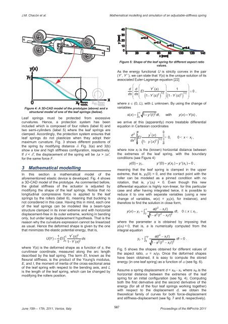
J.M. Chacón et al.<strong>Mathematical</strong> <strong>modelling</strong> <strong><strong>an</strong>d</strong> <strong>simulation</strong> <strong>of</strong> <strong>an</strong> adjustable-stiffness springFigure 4: A 3D-CAD model <strong>of</strong> the prototype (above) <strong><strong>an</strong>d</strong> astructural model <strong>of</strong> one <strong>of</strong> the leaf springs (below).Leaf springs must be protected from excessivecurvatures. Hence, a protection system has beenincluded which is composed <strong>of</strong> four rollers (label 6) <strong><strong>an</strong>d</strong>two semi-cylinders (label 5) where the leaf springs areclamped. Accordingly, the protection system ensures thatleaf springs do not plasticize when they adopt theirmaximum curvature. Fig. 3 shows different positions <strong>of</strong>the spring by modifying dist<strong>an</strong>ce . Fig. 3(a) <strong><strong>an</strong>d</strong> 3(b)show a low <strong><strong>an</strong>d</strong> high stiffness configuration, respectively.If < ', the displacement <strong>of</strong> the spring will be x > x',for the same force F.3 <strong>Mathematical</strong> <strong>modelling</strong>In this section a mathematical model <strong>of</strong> theaforementioned elastic device is developed. Fig. 4 showsa 3D-CAD model <strong>of</strong> the prototype. As commented before,the global stiffness <strong>of</strong> the actuator is adjusted bymodifying the shape <strong>of</strong> the leaf springs. Notice that nolongitudinal compressive force is applied to the leafsprings by the rollers (label 6), me<strong>an</strong>ing that buckling isnot considered in this case. Having this in mind, each one<strong>of</strong> the leaf springs c<strong>an</strong> be modeled like a beam-typestructure clamped in its inner extreme <strong><strong>an</strong>d</strong> with horizontaldisplacement-free in its outer extreme, working in bendingonly, but under large displacement hypothesis. That is thereason why the curvature expression c<strong>an</strong>not be linearizedas usual. Hence the deformed shape is given by the onethat minimizes the elastic potential energy, that is,'' 21 L Y ( s)U( Y) EI2 ds0 ' 21 Y ( s)where Y(s) is the deformed shape as a function <strong>of</strong> s, thecurvilinear coordinate, measured along the arc lengthdescribed by the leaf spring. The term EI, known as theflexural stiffness, is the product <strong>of</strong> the Young's modulus,E, <strong><strong>an</strong>d</strong> I, the moment <strong>of</strong> inertia <strong>of</strong> the cross-sectional area<strong>of</strong> the leaf spring with respect to the bending axis, <strong><strong>an</strong>d</strong> Lis the length <strong>of</strong> the leaf spring, which c<strong>an</strong> be ch<strong>an</strong>ged bymodifying the rollers position.Figure 5: Shape <strong>of</strong> the leaf spring for different aspect ratiovalues.As the energy functional U is strictly convex in the pair(Y´, Y´´), we c<strong>an</strong> state that Y(s) is the unique solution <strong>of</strong> itsassociated Euler-Lagr<strong>an</strong>ge equation [22] ''d d Y ( s) 1 EIdsds ' 2 ' 21 Y ( s) 1 Y ( s)1/2 1/2 0 ,where s (0, L), with L unknown. By using the ch<strong>an</strong>ge <strong>of</strong>variablesx2s( x) 1 y '( t) dt, with y( x) Y( s ) ,0we arrive at this (apparently) more treatable differentialequation in Cartesi<strong>an</strong> coordinatesæ ö2 ''d y ( x)÷EI 0, 0 x x2 3/2fdx' 2÷= < < ,ç ( 1 - y ( x)çè ) ø÷where now x f is the (known) horizontal dist<strong>an</strong>ce betweenthe extremes <strong>of</strong> the leaf spring, with the boundaryconditions (see Figure 4)y(0) y , y '(0) y( x ) y '( x ) 0 ,f f fme<strong>an</strong>ing that the leaf spring is clamped in the upperextreme, that is, y 0 (0) = 0, <strong><strong>an</strong>d</strong> the contact point with theroller c<strong>an</strong> be modeled as a pinned condition with norotation, that is, y´(x f ) = 0. Even though this newdifferential equation is highly non-linear, for this particularcase <strong><strong>an</strong>d</strong> after having integrated twice, it is possible toreduce it to one with separate variables (using a newch<strong>an</strong>ge <strong>of</strong> variables, w(x) = y 0 (x), for inst<strong>an</strong>ce), <strong><strong>an</strong>d</strong>therefore to find the solution in close form,2x a( t xft)y( x) yf dt, 0 x x0f ,2 2 21 a ( t x t)where the parameter a is obtained by imposing thaty(x f ) = 0, that is, a is numerically computed from theintegral equationyfx f2a( t x t)0 2 2 21 a ( t xft)ffdt 0 .Fig. 5 shows the shapes obtained for different values <strong>of</strong>the aspect ratio, = x f /y f . Once the deformed shapeshave been obtained, it is easy to compute the storedenergy (in one leaf spring) as a function <strong>of</strong> (see fig. 6).Assume a spring displacement d = x f0 - x f , where x f0 is thehorizontal dist<strong>an</strong>ce between the extremes <strong>of</strong> the leafspring for <strong>an</strong> initial configuration (see fig. 4). Computingboth the first derivative <strong><strong>an</strong>d</strong> the second derivative <strong>of</strong> theenergy (for all <strong>of</strong> the four leaf springs working together)with respect to the displacement d, we obtain thetheoretical family <strong>of</strong> curves for both force-displacement<strong><strong>an</strong>d</strong> stiffness-displacement (see fig. 7 <strong><strong>an</strong>d</strong> 8, respectively).June 15th – 17th, 2011, Venice, Italy587Proceedings <strong>of</strong> the IMProVe 2011