Improving Helicopter Flight Simulation with Rotor ... - IMProVe2011
Improving Helicopter Flight Simulation with Rotor ... - IMProVe2011
Improving Helicopter Flight Simulation with Rotor ... - IMProVe2011

You also want an ePaper? Increase the reach of your titles
YUMPU automatically turns print PDFs into web optimized ePapers that Google loves.
A.Ceruti et al. <strong>Improving</strong> <strong>Helicopter</strong> <strong>Flight</strong> <strong>Simulation</strong> <strong>with</strong> <strong>Rotor</strong> Vibrations<br />
blades. In the last few times the market started to offer a<br />
series of devices for vibration simulation. The frequency<br />
of waves generated [11] is usually between 0 and 40 Hz,<br />
while the maximum amplitude is of few millimeters.<br />
1.2 This Paper<br />
This paper describes the conceptual design, the<br />
dimensioning, the CAD modelling, the FEM analysis, the<br />
final manufacturing and assembly of a device useful to<br />
simulate helicopter rotor vibration. The design started<br />
from an experimental phase in which the vibrations<br />
recorded onboard a full scale helicopter have been<br />
collected and analysed in the whole flight envelope. The<br />
analysis of the collected data and of helicopters<br />
specifications taken form bibliography, provided a better<br />
understanding of the vibration phenomena and of its<br />
perception by pilots and passengers. The device design<br />
has been carried out applying the classical formulas of<br />
machine dynamics and mechanical dimensioning. The<br />
device has been finally added to an helicopter flight<br />
simulator developed at the Bologna University. Results<br />
obtained show the correct ending of the project and<br />
confirm the design methodology effectiveness.<br />
In the next second paragraph of the paper, the design<br />
methodology is described; the third section contains a<br />
brief introduction to the problem of vibrations in helicopter<br />
and describes the experimental phase of in-flight vibration<br />
data collecting. A brief list of the University of Bologna<br />
helicopter simulator main features is presented in the<br />
fourth section; the product design cycle of the shaker is<br />
reported in the fifth section, starting from conceptual<br />
design up to the installation; a conclusion paragraph<br />
highlights the project results, the advantages in realism<br />
gained and the drawback of the adopted solution.<br />
2 Design Methodology<br />
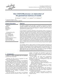
The design methodology followed for this work is<br />
represented in fig. 1, where all of the phases are listed.<br />
One of the most important design phase is the<br />
determination of the frequency and accelerations<br />
amplitudes range of interest. The simulator should in fact<br />
reproduce the vibrations perceived on board a large part<br />
of helicopters. The smallest helicopter are ultralight<br />
machines, <strong>with</strong>out sophisticated devices for vibration<br />
suppression; on the other side, large helicopters present<br />
a better rotor mechanics, high power turbine (or turbines),<br />
takeoff mass up to thousands of Kilograms. One of the<br />
design requirements is so the modularity, as to gain the<br />
possibility to simulate not only one model of helicopter,<br />
but a large class of machines. It is very important to study<br />
the vibrating phenomena over several helicopters so to<br />
cover the most significant vibrations which can be found<br />
in the frequency domain.<br />
This kind of research has been performed using a<br />
powerful mathematical operation called ‘Fourier<br />
Transform’ (described in the next paragraph), which allow<br />
to split a generic time domain signal into the sum of many<br />
different fundamental signals, each carrying a different<br />
single oscillation frequency.<br />
<strong>Helicopter</strong> <strong>Flight</strong><br />
Data Collection Data Processing<br />
Shaker conceptual<br />
design<br />
CAD modelling<br />
FEM analysis<br />
Prototype Construction<br />
Device<br />
Installation/Integration<br />
System Test<br />
Fig. 1: Design phases diagram<br />
Once the vibration amplitudes and frequencies have<br />
been investigated, the conceptual design of the device<br />
can start. Many solutions for vibrations reproduction have<br />
been considered, comparing technical capacity and<br />
drawbacks. The most promising solution have been<br />
deeply analysed in a more detailed design: after a first<br />
rough dimensioning, the device has been modelled <strong>with</strong>in<br />
a CAD environment. In the following a series of FEM<br />
analysis has been deployed to check the design<br />
robustness. The virtual model of the shaker system has<br />
been added to a 3D model of the simulator to verify the<br />
installation and the interface <strong>with</strong> the simulator frame. The<br />
follow-up work has been the manufacturing of a prototype<br />
and its installation on the simulator. A final phase of<br />
testing concludes the design workflow.<br />
3 Vibrations on helicopters<br />
Frequency/<br />
Amplitude<br />
field of<br />
interest<br />
There are different important sources of vibration on<br />
board of an helicopter: They can be in general grouped<br />
into three main categories:<br />
- Main <strong>Rotor</strong> (shaft and blades) induced vibrations;<br />
- Engine and relative gearboxes vibrations;<br />
- Tail <strong>Rotor</strong> (shaft and blades) induced vibrations.<br />
Each of these mechanical groups contain a<br />
considerable amount of moving masses which rotate at a<br />
significant angular speed: main rotor speed is typically<br />
between 300 RPM for large helicopters, up to 600 RPM<br />
for ultralight helicopters. The turbine rotational velocity<br />
can be up to tens thousand of RPM, depending on turbine<br />
diameters. Tail rotor speed is normally a multiple of main<br />
rotor speed, since a rigid mechanical transmission<br />
synchronize the two rotors. Normal rates of transmission<br />
are variable between 4 to 7, depending on the tail rotor<br />
June 15th – 17th, 2011, Venice, Italy<br />
637<br />
Proceedings of the IMProVe 2011