Improving Helicopter Flight Simulation with Rotor ... - IMProVe2011
Improving Helicopter Flight Simulation with Rotor ... - IMProVe2011
Improving Helicopter Flight Simulation with Rotor ... - IMProVe2011

Create successful ePaper yourself
Turn your PDF publications into a flip-book with our unique Google optimized e-Paper software.
A.Ceruti et al. <strong>Improving</strong> <strong>Helicopter</strong> <strong>Flight</strong> <strong>Simulation</strong> <strong>with</strong> <strong>Rotor</strong> Vibrations<br />
Fig. 4: FFT of the vertical vibration measured during a<br />
100 KTS cruise (amplitude vs frequency [Hz])<br />
Fig. 5: FFT of the vertical vibration measured at the VNE<br />
(amplitude vs frequency [Hz])<br />
As it can be seen from the above figures, is clearly<br />
visible that the amplitude peaks are positioned at the<br />
expected frequencies. Furthermore, the amplitude of the<br />
vibrations induced by main rotor is variable <strong>with</strong> flight<br />
phase. Results obtained are in agreement <strong>with</strong><br />
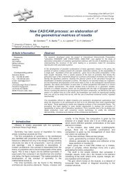
bibliographic data, as Figure 6 and 7 taken from<br />
Bibliography [13], [14], [15] shows. Figure 7 in particular<br />
show the amplitude of vibration of the 4 blade German<br />
helicopter BO 105 as a function of the speed.<br />
Fig. 6: FFT of the BO 105 helicopter in level cruise flight<br />
(Source: O. Dietrich [13] and T. Mannchen[14])<br />
Fig. 7: BO 105 Vibration amplitude <strong>with</strong> speed (Source:<br />
Strehlow et al. [15] and T. Mannchen [14])<br />
The above concerns will drive the design of the device for<br />
the vibrations reproductions. In particular two are the<br />
main issues to consider:<br />
- The rotor speed is constant: the first harmonics<br />
can lie in the interval [10-30] Hz, mainly depending on the<br />
number of blades since the rotation speed is about 400-<br />
600 RPM for all the conventional helicopters.<br />
- The amplitude of the vibrations is variable<br />
depending on the flight phase, from a minimum of 0.01 to<br />
a maximum of 0.15 g, which correspond to 0.1 m/s 2 and<br />
1.5 m/s 2 .<br />
3.1 Vibrations and human body<br />
The body perception of vibrations is mainly due to the<br />
resonance of the internal organs, which is about [16]:<br />
- 7-19 Hz for eyes and head<br />
- 3-5 Hz for heart<br />
- 3-6 Hz for internal organs like liver, spleen, kidney<br />
- 5-12 Hz for spinal column<br />
Furthermore, vibration can be divided in<br />
- “full-body” (industrial machines, air ground and<br />
marine transports, normally passing through feet or seat),<br />
- “hand arm” (Industrial pneumatic and electric tools<br />
hand held, like drill or hammer drill).<br />
Full-body accelerations [17] presents medium-low<br />
frequencies (2-20 Hz) and involves the whole body;<br />
frequency at higher frequency are felt only locally by skin.<br />
<strong>Helicopter</strong>s <strong>with</strong>out vibration compensation systems,<br />
and helicopters <strong>with</strong> small weight presents a peak of<br />
vibrations amplitude for the 1-N/rev frequency.<br />
The most critical vibrations [18] for the human body lie<br />
in the range 4-6 Hz, as the international norm ISO-2631<br />
[19] explains; the interpretation of graphs of iso-exposition<br />
to vibrations shows how a vibration of 6 Hz and 0.3 m/s 2<br />
RMS amplitude can be sustained for 8 hours. The same<br />
value of exposition is prescribed for a vibration of 2.5 m/s 2<br />
(which is 8 time greater) at 60 Hz.<br />
As a conclusion, the most critical frequency in<br />
helicopter flight (<strong>with</strong> reference to body behaviour) seems<br />
to be the first N/rev. This frequency is not so far from the<br />
critical 4-6 Hz range. The other N/rev harmonics, even if in<br />
certain cases (large helicopters <strong>with</strong> vibration suppression<br />
devices) present larger acceleration amplitude, seems to<br />
be less “felt” by the human body.<br />
4 <strong>Helicopter</strong> <strong>Flight</strong> Simulator layout<br />
The Bologna University flight simulator is made up of a<br />
cluster of 3 PC connected <strong>with</strong> a local net providing:<br />
dynamics computation, external visual representation,<br />
flight commands acquisition. The implementation of the<br />
vibration simulation required to dedicate a PC to this task;<br />
the simulation speed is not affected by this new device<br />
since the other two PC are not overcharged. The main<br />
PC1 is connected to the helicopter simulator flight<br />
commands (collective, rudder, cyclic) by a USB port so<br />
that all the commands excursions are acquired in real<br />
time. The flight commands are in fact endowed <strong>with</strong><br />
potentiometer sensors so that each displacement can be<br />
acquired using a dedicated acquisition module, and then<br />
used directly in the simulation program.<br />
A mathematical model of the flight is implemented in<br />
the PC 1. Different helicopter models can be simulated:<br />
the mathematical model is parametric so that new<br />
helicopter model data can be loaded each simulation run.<br />
Position (Lat Long Alt), attitude (Pitch Roll an Yaw), speed<br />
and accelerations are sent to the PC2. The PC 2 provides<br />
the visualization of the external view (based on the free<br />
simulator <strong>Flight</strong>gear) and of the instrument panel. A<br />
second UDP connection links PC1 <strong>with</strong> PC3.<br />
June 15th – 17th, 2011, Venice, Italy<br />
639<br />
Proceedings of the IMProVe 2011