Improving Helicopter Flight Simulation with Rotor ... - IMProVe2011
Improving Helicopter Flight Simulation with Rotor ... - IMProVe2011
Improving Helicopter Flight Simulation with Rotor ... - IMProVe2011

Create successful ePaper yourself
Turn your PDF publications into a flip-book with our unique Google optimized e-Paper software.
A.Ceruti et al. <strong>Improving</strong> <strong>Helicopter</strong> <strong>Flight</strong> <strong>Simulation</strong> <strong>with</strong> <strong>Rotor</strong> Vibrations<br />
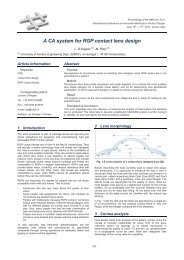
Fig. 10: Conceptual layout of the shaker: motor (green),<br />
eccentric maximum volume (red), frame (white and grey).<br />
5.2 Shaker dimensioning<br />
The equation describing the motion of a system<br />
excited by an harmonic force is:<br />
Mx cx kx F F(<br />
t)<br />
(1)<br />
Where:<br />
M: mass of the system<br />
C: damping<br />
k: stiffness<br />
F(t): exciting force<br />
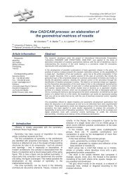
The shaker can be schematized as a vibrodyne: it is a<br />
mechanical system made by two counter-rotating masses<br />
<strong>with</strong> a given eccentricity respect to the rotation axis. The<br />
Figure 11 presents two masses (m1; m2) <strong>with</strong> an opposite<br />
rotational speed (Ω; -Ω), and <strong>with</strong> the same eccentricity<br />
(e).<br />
Fig. 11: Vibrodyne scheme<br />
The centrifugal force acting on the masses are Fc1 and<br />
Fc2, defined as:<br />
Fc1 m e(<br />
)<br />
2<br />
1 ;<br />
Fc2 m e(<br />
)<br />
2<br />
2 (2)<br />
But the forces Fc1 and Fc2 can be decomposed on the<br />
axis x and y of Figure 13, so that:<br />
June 15th – 17th, 2011, Venice, Italy<br />
641<br />
Proceedings of the IMProVe 2011<br />
<br />
2<br />
Fc1_ x m1e( ) cos t<br />
<br />
2<br />
Fc1_ y m1e( ) sin( t)<br />
<br />
2<br />
Fc2 _ x m2e( ) cos t<br />
<br />
2<br />
Fc2 _ y m2e( ) sin( t)<br />
Summing the contributions of the mass 1 and 2 in<br />
direction of the x and y axis it follows:<br />
2 2<br />
Fctotal x m1e( ) cos( t) m2e( ) cos( t)<br />
<br />
2 2<br />
Fctotal y m1e( ) sin( t) m2e( ) sin( t)<br />
If m1= m2 and if a new variable m is defined as m=m1+<br />
m2 it follows:<br />
Fctotal x 0<br />
<br />
Fctotal<br />
y me t<br />
2<br />
( ) sin( )<br />
The shaker dynamic equation will then be<br />
approximated to a single degree of freedom vibration,<br />
where x represent the vertical translation of the system:<br />
2<br />
Mx cx kx me<br />
sin( t)<br />
(7)<br />
This equation can be solved (after an initial transient) in<br />
terms of displacement x, as:<br />
x <br />
2 me / k sin t <br />
<br />
<br />
<br />
2<br />
2<br />
2<br />
2<br />
n n<br />
<br />
1 / 2 / <br />
<br />
Where:<br />
k / M ; c / 2m<br />
n n<br />
The dimensions required for the design of the shaker is<br />
the product of eccentric mass per eccentricity and the<br />
spring stiffness; the requirements are the whole system<br />
maximum acceleration (in terms of [g] or [m/s 2 ]) and a<br />
(3)<br />
(4)<br />
(5)<br />
(6)<br />
(8)