Improving Helicopter Flight Simulation with Rotor ... - IMProVe2011
Improving Helicopter Flight Simulation with Rotor ... - IMProVe2011
Improving Helicopter Flight Simulation with Rotor ... - IMProVe2011

You also want an ePaper? Increase the reach of your titles
YUMPU automatically turns print PDFs into web optimized ePapers that Google loves.
A.Ceruti et al. <strong>Improving</strong> <strong>Helicopter</strong> <strong>Flight</strong> <strong>Simulation</strong> <strong>with</strong> <strong>Rotor</strong> Vibrations<br />
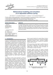
Fig.15: 3D model of the shaker frame<br />
5.4 FEM analysis<br />
A Finite Element analysis was required to check<br />
dynamic interference between the simulator frame and<br />
the shaker frame. The software used is Patran for<br />
preprocessing and post-processing, and Nastran as the<br />
main solver. For instance, the model of the shaker<br />
support structure has been modeled <strong>with</strong>in the Patran<br />
software: mono-dimensional ‘beam’ type elements have<br />
been applied to simulate all of the metal tubes and<br />
sections in the structure. A single concentrated ‘mass<br />
element’ positioned on the motor CoG and joined to the<br />
support plate through ‘rigid elements’ has been used to<br />
model the motor itself. The complete model is made of<br />
422 nodes and 458 elements, for a total of 2261 degrees<br />
of freedom (DOF). Element types used in the model are:<br />
Beam, Plate, Mass, Rigid.<br />
Beam elements are used to represent tubes and bars,<br />
<strong>with</strong> the following dimensions: “L” type beam dimension<br />
50x50x5 mm, Plain beam of 40x5 mm, Plain beam of<br />
50x8 mm, Plain beam of 55x10 mm, Plain beam of 50x10<br />
mm, Square beam of 40x40x5 mm, Bar <strong>with</strong> a diameter of<br />
D=20 mm.<br />
The material used in the FEM modeling process is<br />
carpentry steel which has been chosen for cost and for<br />
weldability. Its main characteristics are:<br />
- Young Modulus: 2.1 e11 N/mm 2<br />
- Poisson coefficient: 0.29<br />
- Density: 7850 Kg/m3<br />
- Max design Tension: 200 N/m 2<br />
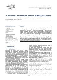
The model (Fig. 16) constraints consist in 4 joints<br />
(each of them blocking all 6 degrees of freedom)<br />
positioned in the upper part of the structure, at the<br />
connection between the seat and the simulator.<br />
Fig. 16: FEM model of the frame and shaker<br />
The natural vibration modes have been found to be:<br />
- Mode 1 : 49 Hz<br />
- Mode 2 : 64 Hz<br />
- Mode 3 : 78 Hz<br />
- Mode 4 : 146 Hz<br />
Among all these modes, the most interesting are those<br />
presenting a deformed which agrees <strong>with</strong> the direction of<br />
the shaker harmonic excitation force, because they can<br />
be subject to resonance.<br />
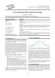
Fig. 17: First (left) vibration mode: 49 Hz; fourth (right)<br />
vibration mode: 146 Hz<br />
Following these considerations, the shaker support<br />
structure modes which have a practical interest are the<br />
first one at 49 Hz and the fourth at 146 Hz, which are<br />
beyond the work frequency of the device. A similar<br />
investigation has been performed for the simulator frame.<br />
5.5 Electric Motor<br />
The electric motor needed to move the eccentric<br />
mechanism has been selected considering a maximum<br />
frequency for the first harmonic of 40 Hz. The torque of<br />
the motor is not a mandatory requirement since the only<br />
reaction is given by the friction of the bearings. Transitory<br />
dynamic is not so fast; the changes in amplitude of<br />
vibrations are small due to the inertia of the helicopter,<br />
which speeds up and decelerates in quite long times.<br />
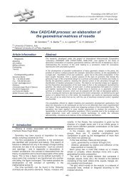
The characteristic of the motor (in Figure 18) are:<br />
- maximum power output = 550 Watt;<br />
- single phase, bipolar electric motor;<br />
- max angular speed of 2440 RPM<br />
- endowed <strong>with</strong> an inverter for speed settings.<br />
Fig. 18: Electric motor and inverter to set the rotation speed.<br />
The stepper motor is small enough to fit into the<br />
assembly: the torque required is very low and the correct<br />
angular position is provided by a look-up table which sets<br />
the number of motor steps needed to move the screw in<br />
order to obtain the desired eccentricity. A control board is<br />
linked to PC3, which drives the stepper motor and<br />
computes (in open chain loop) the current and required<br />
June 15th – 17th, 2011, Venice, Italy<br />
643<br />
Proceedings of the IMProVe 2011