Datasheet 3E-3 (Issue 3.0) Relay Style QBCA1 - Invensys Rail
Datasheet 3E-3 (Issue 3.0) Relay Style QBCA1 - Invensys Rail
Datasheet 3E-3 (Issue 3.0) Relay Style QBCA1 - Invensys Rail

Create successful ePaper yourself
Turn your PDF publications into a flip-book with our unique Google optimized e-Paper software.
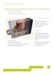
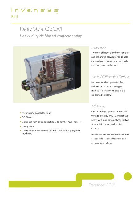
<strong>Relay</strong> <strong>Style</strong> <strong>QBCA1</strong><br />
Heavy duty dc biased contactor relay<br />
• AC immune contactor relay<br />
• DC Biased<br />
• Complies with BR specification 943 or 966, Appendix F4<br />
• Heavy duty<br />
• Contacts and connections suit direct switching of point<br />
machines<br />
Heavy duty<br />
Two sets of heavy duty front contacts<br />
and magnetic blowouts for double<br />
cutting high current dc or ac loads,<br />
such as point machines.<br />
Use in AC Electrified Territory<br />
Immune to false operation from<br />
induced ac induced voltages,<br />
making it a relay of choice in ac<br />
electrified territory<br />
DC Biased<br />
<strong>QBCA1</strong> relays operate on normal<br />
voltage polarity only. Connect two<br />
relays with opposite polarity for two<br />
wire point control and similar<br />
circuits.<br />
Bias levels are maintained even with<br />
reasonable levels of forward and<br />
reverse overvoltage.<br />
<strong>Datasheet</strong> <strong>3E</strong>-3
Description<br />
A single wound dc biased ac immune<br />
relay, compliant with<br />
BR Specifications 943 or 966<br />
Appendix F4.<br />
Heavy Duty Contacts<br />
Fitted with two heavy duty front<br />
contacts with magnetic blowouts.<br />
Each heavy duty contact terminal is<br />
connected to two plugboard<br />
connectors.<br />
Wire each connector with two wires in<br />
parallel to handle heavy currents. For<br />
efficient operation of the magnetic<br />
blowouts in dc operation, set the<br />
connection polarity as shown below.<br />
Recommended Wiring 1<br />
• Arrangement of connection of back<br />
contacts to detect welded heavy<br />
duty front contact.<br />
A5 A6 D5 D6<br />
A7 A8 D7 D8<br />
Use this arrangement to give<br />
detection of a welded heavy–duty<br />
front contact.<br />
• Arrangement of connecting wires to<br />
the heavy–duty front contacts.<br />
+ ~<br />
PLUGBOARD<br />
C1<br />
C2<br />
Observe the polarities shown when<br />
using a dc supply.<br />
1. Wiring diagrams based on diagrams in BR<br />
Specifications 943 and 966 Appendix 4.<br />
C3<br />
C4<br />
Specifications (20°C)<br />
Piece<br />
number<br />
Nominal<br />
working<br />
volts<br />
Contacts Coil<br />
resistance<br />
ohms<br />
179–185 Normanby Rd (Locked Bag 66), South Melbourne, Victoria 3205, Australia<br />
T +61 1300 724 518 F +61 3 9233 8777 ABN 78 000 102 483<br />
E enquiries.asiapacific@invensysrail.com W http://www.invensysrail.com<br />
Maximum<br />
full<br />
operating<br />
volts<br />
<strong>Datasheet</strong> <strong>3E</strong>-3 issue <strong>3.0</strong><br />
Minimum<br />
release<br />
volts<br />
Piece<br />
number<br />
Plugboard<br />
Code<br />
holes<br />
M25066 50 2HF4B 940 40 7.5 M23430 BCFHK<br />
M25067 24 2HF4B 195 19.2 3.6 M23429 BCEJK<br />
M25068 50 2HF4F4B 940 40 7.5 M25451 BEGHJ<br />
M25069 24 2HF4F4B 195 19.2 3.6 M25452 BEFHJ<br />
M25070 12 2HF4F4B 55 9.6 1.8 M25479 ABCKS<br />
M25098 50 2HF6B 940 40 7.5 M25495 ADFHS<br />
Power<br />
Less than 3 W<br />
consumption<br />
Reverse Polarity Up to 20 times rated voltage without<br />
operating<br />
Immunised 12 V relay 500 V ac<br />
24 V relay 1000 V ac<br />
50 V relay 1000 V ac<br />
Heavy Duty<br />
Contacts<br />
Make and carry 30 A @ 110 V ac or dc for 10 s (50% duty cycle)<br />
Layout of Contacts (Rear View)<br />
Contacts: F = Front, B = Back<br />
Break 30 A @ 110 V ac or dc > 500 times<br />
Break 100 A dc @ 130 V at least once<br />
Not weld at < 200 A dc 130 Vdc prospective<br />
A B C D A B C D A B C D<br />
1<br />
2<br />
SUPPLY<br />
+<br />
1<br />
2<br />
F SUPPLY<br />
+<br />
F SUPPLY<br />
+<br />
3<br />
4<br />
HF<br />
+<br />
3<br />
4<br />
F<br />
HF<br />
+<br />
F B<br />
HF<br />
+<br />
B<br />
LOAD<br />
5<br />
B LOAD<br />
-<br />
B<br />
HF<br />
-<br />
5<br />
6 6<br />
7<br />
B B 7<br />
8 8<br />
SUPPLY<br />
LOAD<br />
B LOAD<br />
-<br />
HF<br />
LOAD<br />
B B B B<br />
-<br />
-<br />
SUPPLY<br />
B B LOAD<br />
-<br />
HF<br />
SUPPLY<br />
R1 C+ C- R2 C+ C- C+ C-<br />
R3 R4<br />
2HF 4B<br />
BR Spec 943<br />
2HF 4F 4B<br />
BR Spec 966<br />
App F4<br />
2HF 6B<br />
B