Fiber Polarity Simplified
Fiber Polarity Simplified
Fiber Polarity Simplified

You also want an ePaper? Increase the reach of your titles
YUMPU automatically turns print PDFs into web optimized ePapers that Google loves.
<strong>Fiber</strong> <strong>Polarity</strong> <strong>Simplified</strong><br />
TM<br />
Our commitment. Your advantage.
<strong>Fiber</strong> <strong>Polarity</strong> <strong>Simplified</strong><br />
“Flipped”, “Straight”, “A-to-B” - confused about fiber polarity?<br />
AMP, AMP NETCONNECT, NETCONNECT, TE Logo, and Tyco Electronics<br />
are trademarks.<br />
©Copyright 2009 Tyco Electronics Corporation. All Rights Reserved.<br />
800-553-0938<br />
www.ampnetconnect.com<br />
FIBER POLARITY SIMPLIFIED<br />
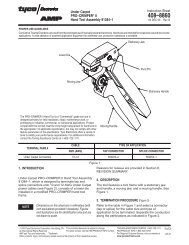
Correct polarity of a few fiber pairs to multiple trunk cables between enclosures can be a bit<br />
confusing. <strong>Fiber</strong> adapters are available with six or twelve duplex connections, and depending<br />
on the enclosure design, the adapters can be mounted in a horizontal or vertical orientation.<br />
6 Duplex LC Adapters<br />
This paper explains a few basic concepts following industry standard recommendations to<br />
help clarify fiber polarity.<br />
Lets start by reviewing the basic connection between two fiber transceivers.<br />
Keep those bits flowing............<br />
Example Adapter Plates<br />
12 Duplex LC Adapters<br />
Simply stated, the polarity of the fiber installation must connect the transmit ports to the<br />
receive ports of the fiber transceivers to transfer data.<br />
“Keyways up”<br />
Tx Rx<br />
Note the adapter keyways are on top (Keyways up) for both transceivers, and when viewed<br />
from the front or open port side, the transmit port (Tx) is on the left, and the receive port (Rx)<br />
is on the right.<br />
The top view shows the keyways up position with the Tx on the left and Rx on the right when<br />
viewed from the front or open port side.<br />
Tx<br />
Rx<br />
Top View<br />
2
AMP, AMP NETCONNECT, NETCONNECT, TE Logo, and Tyco Electronics<br />
are trademarks.<br />
©Copyright 2009 Tyco Electronics Corporation. All Rights Reserved.<br />
800-553-0938<br />
www.ampnetconnect.com<br />
FIBER POLARITY SIMPLIFIED<br />
Lets connect the transmit and receive ports with two simplex cable assemblies.<br />
“Keyways up”<br />
Rx<br />
Tx<br />
Transceiver 1<br />
With “keyways up” and viewing from the open port side, the Rx is on the right and the Tx on<br />
the left for both transceivers.<br />
So when connecting transmit to receive in the above example, there’s a pattern of Right port<br />
to Left port or Left port to Right port connection with the keyways up and viewed from the<br />
open port side.<br />
Instead of Tx to Rx or left port to right port, industry standards uses “A” and “B” indicators to<br />
maintain polarity throughout the fiber channel. With the adapter “keyways up”, and viewed<br />
from the open port side, “A” is on the right, and “B” is on the left.<br />
So lets replace the Rx to Tx with “A” to “B” in a set of fiber adapters. The figure below simulates<br />
a connection between two fiber enclosures or an enclosure to work area outlet connection.<br />
“Keyways up”<br />
“Key up”<br />
View<br />
Assembly 1<br />
Assembly 2<br />
View<br />
“Key up”<br />
B A<br />
B<br />
A<br />
B<br />
“Key up”<br />
View<br />
Note the position of “A” and “B” when viewed from<br />
the other side of the adapter.<br />
With the “keyways up” and viewed from the open<br />
port side, “A” is on the right, and “B” is on the left.<br />
“Key up”<br />
View<br />
“Keyways up”<br />
Tx<br />
Rx<br />
Transceiver 2<br />
“Keyways up”<br />
A<br />
A B<br />
3
Duplex Patch Cords<br />
The “Key” is the Key<br />
AMP, AMP NETCONNECT, NETCONNECT, TE Logo, and Tyco Electronics<br />
are trademarks.<br />
©Copyright 2009 Tyco Electronics Corporation. All Rights Reserved.<br />
800-553-0938<br />
www.ampnetconnect.com<br />
FIBER POLARITY SIMPLIFIED<br />
Combining these simplex connector assemblies into a duplex assembly produces an industry<br />
standard patch cord configured with “A” connecting to “B”. This configuration is commonly<br />
called “Flipped”.<br />
AMP NETCONNECT MT-RJ, SC, and LC duplex assemblies are configured per the industry<br />
standards configuration of A-to-B.<br />
These patch cords provide the correct polarity for patch panel to equipment and work area<br />
outlet to equipment connections.<br />
A<br />
B<br />
At this point, we have established that an A-to-B and B-to-A connection must be in place to<br />
keep the correct transmit to receive path.<br />
The next important concept to understand is the correct location of A and B as the fiber<br />
adapter is rotated in various positions. The adapter plates can be installed horizontally or vertically<br />
or with the port ID’s ascending or descending. Manufacturer’s placement of six vs<br />
twelve duplex adapters on an adapter plate also changes the orientation of the adapters.<br />
As previously explained, the “key” to identifying the A and B locations in the adapter is the<br />
position of the connector keyway.<br />
For example, the following LC adapters are shown with the correct A and B indicators.<br />
Note the locations of A and B for the different adapter orientations.<br />
With the “keyways up” and viewing from the open port side, “A” is on the right, and “B” is on<br />
the left.<br />
“Keyways up”<br />
B A<br />
B<br />
A<br />
“Keyways up”<br />
LC Duplex Assembly<br />
“Keyways up”<br />
B A<br />
A<br />
B<br />
“Keyways up”<br />
B<br />
A<br />
4
Lets Review.......<br />
B<br />
2<br />
A<br />
B<br />
1<br />
AMP, AMP NETCONNECT, NETCONNECT, TE Logo, and Tyco Electronics<br />
are trademarks.<br />
©Copyright 2009 Tyco Electronics Corporation. All Rights Reserved.<br />
A<br />
800-553-0938<br />
www.ampnetconnect.com<br />
FIBER POLARITY SIMPLIFIED<br />
Established that A-to-B and B-to-A connections must be in place to keep the correct transmit<br />
to receive path.<br />
“Standard” duplex fiber patch cords are A-B and B-A compliant.<br />
The location of A and B identifiers in a fiber adapter is relative to the connector keyway.<br />
The next few sections show the fiber polarity for various adapter to adapter connections.<br />
Patch Panel Connections<br />
The following example is a fiber connection between panel adapter plates.<br />
Note the orientation of the adapter and the A-to-B to B-to-A connections for the fiber pair.<br />
Rear View Panel 2<br />
B<br />
B A<br />
B A<br />
Top View<br />
B<br />
2<br />
A<br />
Rear View Panel 1<br />
A B<br />
A<br />
B<br />
1<br />
A<br />
5
AMP, AMP NETCONNECT, NETCONNECT, TE Logo, and Tyco Electronics<br />
are trademarks.<br />
©Copyright 2009 Tyco Electronics Corporation. All Rights Reserved.<br />
800-553-0938<br />
www.ampnetconnect.com<br />
FIBER POLARITY SIMPLIFIED<br />
The following examples are connections between panels using 6 LC duplex adapter plates.<br />
View from the open port side and with the keyway up to determine the location of A and B.<br />
6 5 4 3 2 1<br />
Rear View Panel 2<br />
Horizontal Adapter Plates<br />
6 5 4 3 2 1<br />
Rear View Panel 2<br />
A<br />
1<br />
2<br />
3<br />
4<br />
5<br />
6<br />
Rear View Panel 2<br />
B<br />
A<br />
6 5 4 3 2 1<br />
Rear View Panel 1<br />
1<br />
2<br />
3<br />
4<br />
5<br />
6<br />
Rear View Panel 1<br />
A<br />
Horizontal and Vertical<br />
Adapter Plates<br />
Vertical Adapter Plates<br />
B<br />
B<br />
1<br />
2<br />
3<br />
4<br />
5<br />
6<br />
Rear View Panel 1<br />
6
Multiple Connections<br />
RX<br />
TX<br />
B<br />
A<br />
<strong>Polarity</strong> Examples<br />
A B A<br />
B<br />
AMP, AMP NETCONNECT, NETCONNECT, TE Logo, and Tyco Electronics<br />
are trademarks.<br />
©Copyright 2009 Tyco Electronics Corporation. All Rights Reserved.<br />
800-553-0938<br />
www.ampnetconnect.com<br />
FIBER POLARITY SIMPLIFIED<br />
For multiple connection points, keep A-to-B and B-to-A to maintain the transmit<br />
to receive path.<br />
The following examples are backbone connections with 24-fiber cable containing two 12-fiber<br />
subunits. Each subunit contains 12 color-coded fibers that are grouped in pairs during the<br />
installation process to form 2-fiber transmission paths.<br />
The following chart lists the fiber pair color code per industry standard ANSI/TIA-598-C,<br />
Optical <strong>Fiber</strong> Cable Color Coding.<br />
<strong>Fiber</strong> Color <strong>Fiber</strong> Number <strong>Fiber</strong> Pair<br />
Blue<br />
Orange<br />
1<br />
2<br />
1<br />
Green<br />
Brown<br />
3<br />
4<br />
2<br />
Slate<br />
White<br />
5<br />
6<br />
3<br />
Red<br />
Black<br />
7<br />
8<br />
4<br />
Yellow<br />
Violet<br />
9<br />
10<br />
5<br />
Rose<br />
Aqua<br />
11<br />
12<br />
6<br />
B A B A<br />
A B A B A B<br />
Note: An even or odd number of connection points or “hops” does not affect the<br />
polarity outcome. Keep A-to-B and B-to-A for any number of fiber segments to<br />
maintain polarity.<br />
TX<br />
RX<br />
7
Patch Panel 2<br />
AMP, AMP NETCONNECT, NETCONNECT, TE Logo, and Tyco Electronics<br />
are trademarks.<br />
©Copyright 2009 Tyco Electronics Corporation. All Rights Reserved.<br />
B A<br />
A<br />
B<br />
800-553-0938<br />
www.ampnetconnect.com<br />
FIBER POLARITY SIMPLIFIED<br />
The first example pairs the fibers for each subunit in the same A and B adapter position.<br />
Examining the Blue/Orange pair for each 12-fiber subunit in Panel 1, the Blue fibers are in the<br />
A position, and the Orange fibers are in the B position. With the adapter keys in opposite<br />
directions within the single plate, the fiber color scheme is reversed for the two 12-fiber subunits.<br />
When connecting panels together using dual “row” adapter plates, the connection should be<br />
between adapter rows with the same keyway orientation. See the location of the subunit<br />
fibers in the adapters shown below.<br />
When a connection occurs between adapters in the same keyway orientation, the fibers in<br />
Panel 2 will be color swapped in a reverse-pair position to maintain the A-to-B connection.<br />
A<br />
B<br />
Subunit 2 <strong>Fiber</strong>s<br />
Subunit 1 <strong>Fiber</strong>s<br />
Subunit 2 <strong>Fiber</strong>s<br />
Rear View of Adapter Plates<br />
B<br />
A<br />
Patch Panel 1<br />
Subunit 1 <strong>Fiber</strong>s<br />
8
Patch Panel 2<br />
A<br />
B<br />
A<br />
B<br />
A<br />
B<br />
AMP, AMP NETCONNECT, NETCONNECT, TE Logo, and Tyco Electronics<br />
are trademarks.<br />
©Copyright 2009 Tyco Electronics Corporation. All Rights Reserved.<br />
800-553-0938<br />
www.ampnetconnect.com<br />
FIBER POLARITY SIMPLIFIED<br />
This example pairs the fibers for each subunit in the same orientation per the standard twelve<br />
color code pattern. Examining the Blue/Orange pair for each 12-fiber subunit in Panel 1, the<br />
Blue fibers for each subunit are in the first position, Orange for the second position, and so<br />
forth. The results are a consistent color scheme for both “rows” of the adapter plate.<br />
As mentioned in the previous example, when connecting panels together using dual “row”<br />
adapter plates, the connection should be between adapter rows with the same keyway orientation.<br />
See the location of the subunit fibers in the adapters shown below.<br />
When a connection occurs between adapters in the same keyway orientation, the fibers in<br />
Panel 2 will be color swapped in a reverse-pair position to maintain the A-to-B connection.<br />
Subunit 2 <strong>Fiber</strong>s<br />
Rear View of Adapter Plates<br />
B<br />
A<br />
Patch Panel 1<br />
Subunit 2 <strong>Fiber</strong>s Subunit 1 <strong>Fiber</strong>s Subunit 1 <strong>Fiber</strong>s<br />
9
AMP, AMP NETCONNECT, NETCONNECT, TE Logo, and Tyco Electronics<br />
are trademarks.<br />
©Copyright 2009 Tyco Electronics Corporation. All Rights Reserved.<br />
800-553-0938<br />
www.ampnetconnect.com<br />
FIBER POLARITY SIMPLIFIED<br />
Here is an example of Centralized optical fiber cabling for a fiber-to-the-desk installation.<br />
<strong>Fiber</strong><br />
Enclosure<br />
Conclusion<br />
A B<br />
B<br />
Telecommunications<br />
Room<br />
<strong>Fiber</strong><br />
Enclosure<br />
A B<br />
B<br />
Equipment Room<br />
A<br />
Horizontal Cable<br />
Backbone Cable<br />
A<br />
Patch Cord<br />
Network<br />
Equipment<br />
Telecommunications<br />
Outlet<br />
The guidelines presented in this paper follow the recommendations of ANSI/TIA-568-C<br />
industry standards for reverse-pair polarity.<br />
The location of A and B identifiers in a fiber adapter is relative to the connector keyway.<br />
For any number of connection points or orientation of fiber adapters, an A-to-B and B-to-A<br />
connection will maintain fiber polarity throughout the fiber channel and ensure transmit-toreceive<br />
connectivity.<br />
B<br />
A<br />
A<br />
B<br />
Patch Cord<br />
Media Converter<br />
or <strong>Fiber</strong> NIC<br />
10