

Under Carpet PRO-CRIMPER II Hand Tool Assembly 91384-1
Under Carpet PRO-CRIMPER II Hand Tool Assembly 91384-1
Under Carpet PRO-CRIMPER II Hand Tool Assembly 91384-1

You also want an ePaper? Increase the reach of your titles
YUMPU automatically turns print PDFs into web optimized ePapers that Google loves.
2003 Tyco Electronics Corporation, Harrisburg, PA This controlled document is subject to change.<br />
All International Rights Reserved<br />
For latest revision, call the FAX/<strong>PRO</strong>DUCT INFO number.<br />
AMP and Tyco are trademarks. *Trademark<br />
Other products, logos, and company names used are the property of their respective owners.<br />
<strong>Under</strong> <strong>Carpet</strong><br />
Instruction Sheet<br />
<strong>PRO</strong>–<strong>CRIMPER</strong>* <strong>II</strong> 408–8860<br />
<strong>Hand</strong> <strong>Tool</strong> <strong>Assembly</strong> <strong>91384</strong>–1<br />
02 DEC 03 Rev O<br />
<strong>PRO</strong>PER USE GUIDELINES<br />
Cumulative Trauma Disorders can result from the prolonged use of manually powered hand tools. <strong>Hand</strong> tools are intended for occasional use and low volume<br />
applications. A wide selection of powered application equipment for extended–use, production operations is available.<br />
The <strong>PRO</strong>–<strong>CRIMPER</strong> <strong>II</strong> <strong>Hand</strong> <strong>Tool</strong> is a “Commercial” grade tool and is<br />
designed primarily for field installation, repair, maintenance work, or<br />
prototyping in industrial, commercial, or institutional applications. Product<br />
crimped with this tool will meet the crimp height requirement for hand tools in<br />
the appropriate 114 application specification, but may not comply with other<br />
feature parameters of the specification. Tyco Electronics offers a variety of<br />
tools to satisfy your performance requirements. For additional information,<br />
contact the <strong>Tool</strong>ing Assistance Center at 1–800–722–1111.<br />
TERMINAL FAMILYY<br />
Lower Die<br />
Moving Jaw<br />
Moving <strong>Hand</strong>le<br />
Stationary Jaw<br />
Pivot Pin<br />
CABLE TYPE OF APPLICATION<br />
Stationary <strong>Hand</strong>le<br />
SIZE (AWG) TAP CONNECTOR SPLICE CONNECTOR<br />
<strong>Under</strong> <strong>Carpet</strong> Connectors 10–12 553455–2 553454–1<br />
1. INTRODUCTION<br />
<strong>Under</strong> <strong>Carpet</strong> <strong>PRO</strong>–<strong>CRIMPER</strong> <strong>II</strong> <strong>Hand</strong> <strong>Tool</strong> <strong>Assembly</strong><br />
<strong>91384</strong>–1, which is designed to terminate tap and<br />
splice connectors onto 10 and 12 AWG <strong>Under</strong> <strong>Carpet</strong><br />
power cables (see Figure 2), consists of a lower die<br />
installed in a modified <strong>PRO</strong>–<strong>CRIMPER</strong> hand tool<br />
frame.<br />
NOTE<br />
Dimensions on this sheet are in millimeters [with<br />
inch equivalents provided in brackets]. Figures<br />
and illustrations are for identification only and are<br />
not drawn to scale.<br />
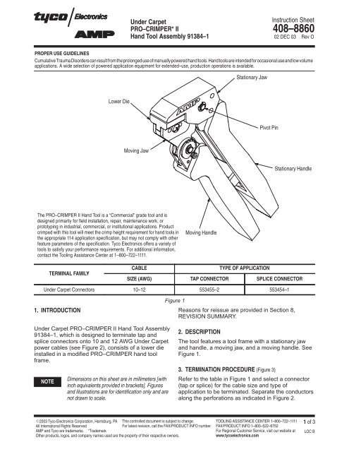
Figure 1<br />
Reasons for reissue are provided in Section 8,<br />
REVISION SUMMARY.<br />
2. DESCRIPTION<br />
The tool features a tool frame with a stationary jaw<br />
and handle, a moving jaw, and a moving handle. See<br />
Figure 1.<br />
3. TERMINATION <strong>PRO</strong>CEDURE (Figure 3)<br />
Refer to the table in Figure 1 and select a connector<br />
(tap or splice) for the cable size and type of<br />
application to be terminated. Separate the conductors<br />
along the perforations as indicated in Figure 2.<br />
TOOLING ASSISTANCE CENTER 1–800–722–1111<br />
FAX/<strong>PRO</strong>DUCT INFO 1–800–522–6752<br />
For Regional Customer Service, visit our website at<br />
www.tycoelectronics.com<br />
1 of 3<br />
LOC B
50.8 [2.000]<br />
152.4 [6.000]<br />
2 of 3<br />
Splice Connector<br />
3.18 [.125] (Refer to Instruction Sheet<br />
408–3128)<br />
Cover (Typ)<br />
Tap Connector<br />
(Refer to Instruction Sheet<br />
408–3127)<br />
3.18 [.125]<br />
Figure 2<br />
<strong>Under</strong> <strong>Carpet</strong> <strong>PRO</strong>–<strong>CRIMPER</strong> <strong>II</strong> <strong>Hand</strong> <strong>Tool</strong> <strong>Assembly</strong> <strong>91384</strong>–1<br />
Terminating<br />
Tines (Typ)<br />
152.4 [6.000]<br />
Figure 3<br />
CAUTION<br />
Proceed as follows:<br />
408–8860<br />
Before starting termination, refer to the instruction<br />
sheets packaged with the tap and splice<br />
connectors for preparation procedures and<br />
assembly sequence. The applicable sheets are<br />
referenced in Figure 2. Failure to do so could<br />
prevent sealing of insulation patches.<br />
1. Make sure flat side of hand tool is parallel with<br />
floor.<br />
2. Gently lift cable and straddle hand tool jaws with<br />
connector and cable.<br />
3. Squeeze tool handles together until the one<br />
handle bottoms on the handle stop.<br />
4. Allow tool handles to open FULLY and remove<br />
hand tool from connector.<br />
5. Repeat Steps 1 through 4 as necessary for one<br />
side of connector and cable.<br />
4. CRIMP HEIGHT ADJUSTMENT<br />
This tool is permanently set to position No. 7. No<br />
adjustment is necessary.<br />
Splice Connector Tap Connector<br />
Rev O
5. MAINTENANCE<br />
Ensure that the tool and lower die is kept clean by<br />
wiping them with a clean, soft cloth. Remove any<br />
debris with a clean, soft brush. Do not use objects<br />
that could damage the tool. When not in use, keep<br />
handles closed to prevent objects from becoming<br />
lodged in the lower die, and store in a clean, dry area.<br />
6. VISUAL INSPECTION<br />
The lower die should be inspected on a regular basis<br />
to ensure it has not become worn or damaged.<br />
Inspect the crimp sections for flattened, chipped,<br />
worn, or broken areas. If damage or abnormal wear is<br />
evident, the tool must be replaced. See Section 7,<br />
REPLACEMENT.<br />
6.1. Gaging the Crimping Chamber<br />
This inspection requires the use of a GO NO–GO<br />
gage conforming to the dimensions shown in<br />
Figure 4. Tyco Electronics does not manufacture or<br />
market these gages.<br />
Proceed as follows:<br />
1. Close the tool handles until the one handle<br />
bottoms on the handle stop, then HOLD in this<br />
position. Do NOT force the handles beyond initial<br />
contact. Refer to Paragraph 6.2, <strong>Tool</strong> Closure<br />
Inspection.<br />
2. Align the GO element with the jaws. Push<br />
element straight into the jaws without using force.<br />
The GO element must pass completely through as<br />
shown in Figure 4.<br />
3. Align the NO–GO element and try to insert it<br />
straight into the jaws. The NO–GO element may<br />
start entry but must not pass completely through<br />
as shown in Figure 4.<br />
If the jaws conform to the gage inspection, the tool is<br />
considered dimensionally correct and should be<br />
lubricated with a THIN coat of any good SAE No. 20<br />
motor oil. If not, the tool must be repaired before it is<br />
returned to service.<br />
6.2. <strong>Tool</strong> Closure Inspection<br />
Squeeze the tool handles together until the one<br />
handle bottoms on the handle stop. The jaws should<br />
bottom properly, and they should conform to the<br />
gaging dimensions as shown in Figure 4.<br />
Rev O<br />
<strong>Under</strong> <strong>Carpet</strong> <strong>PRO</strong>–<strong>CRIMPER</strong> <strong>II</strong> <strong>Hand</strong> <strong>Tool</strong> <strong>Assembly</strong> <strong>91384</strong>–1<br />
ÍÍÍ<br />
ÍÍÍ<br />
4.06 [.160]<br />
ÍÍÍ<br />
ÍÍÍ<br />
ÍÍÍNO–GO<br />
ELEMENT<br />
76.2 [3.000] Min.<br />
20.32 [.800] Min. (Typ)<br />
6.35 [.250] (Typ)<br />
NO–GO Dim. 1.68 [.066]<br />
7. REPLACEMENT<br />
Suggested Plug Gage Design<br />
NO–GO GO<br />
Figure 4<br />
12.7 [.500]<br />
GO Dim. 1.47 [.058]<br />
ÍÍÍ<br />
ÍÍÍ<br />
ÍÍÍ<br />
ÍÍÍ<br />
ÍÍÍ<br />
408–8860<br />
GO<br />
ELEMENT<br />
Customer–replaceable parts are available separately,<br />
Repair Kit 679221–1 includes a replacement nut and<br />
a variety of pins, rings, screws, and springs. Order<br />
the repair kit and replaceable parts through your Tyco<br />
Electronics Representative, or call 1–800–526–5142,<br />
or send a facsimile of your purchase order to<br />
1–717–986–7605, or write to:<br />
CUSTOMER SERVICE (38–35)<br />
TYCO ELECTRONICS CORPORATION<br />
P.O. BOX 3608<br />
HARRISBURG, PA 17105–3608<br />
8. REVISION SUMMARY<br />
Per EC: 0990–1208–03<br />
Initial release of document<br />
3 of 3


