NETCONNECT AMPTRAC 1U 24-Port Patch Panel Drawers ...
NETCONNECT AMPTRAC 1U 24-Port Patch Panel Drawers ...
NETCONNECT AMPTRAC 1U 24-Port Patch Panel Drawers ...

Create successful ePaper yourself
Turn your PDF publications into a flip-book with our unique Google optimized e-Paper software.
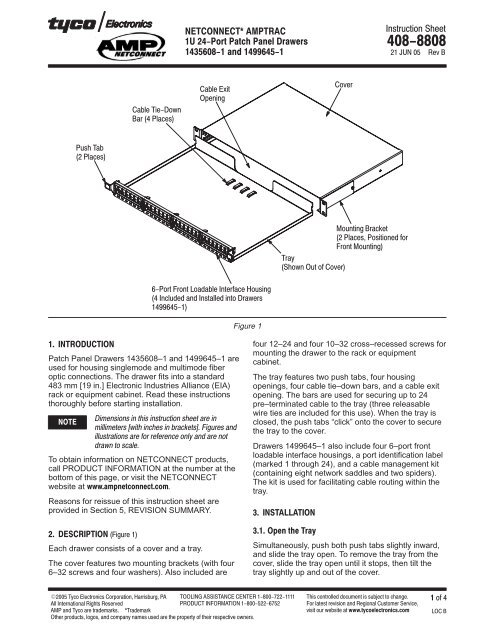
<strong>Patch</strong> <strong>Panel</strong> <strong>Drawers</strong> 1435608–1 and 1499645–1 are<br />
used for housing singlemode and multimode fiber<br />
optic connections. The drawer fits into a standard<br />
483 mm [19 in.] Electronic Industries Alliance (EIA)<br />
rack or equipment cabinet. Read these instructions<br />
thoroughly before starting installation.<br />
<br />
<br />
<br />
<br />
<br />
To obtain information on <strong>NETCONNECT</strong> products,<br />
call PRODUCT INFORMATION at the number at the<br />
bottom of this page, or visit the <strong>NETCONNECT</strong><br />
website at <br />
Reasons for reissue of this instruction sheet are<br />
provided in Section 5, REVISION SUMMARY.<br />
<br />
Each drawer consists of a cover and a tray.<br />
The cover features two mounting brackets (with four<br />
6–32 screws and four washers). Also included are<br />
Figure 1<br />
<br />
<br />
<br />
<br />
<br />
<br />
<br />
<br />
<br />
<br />
<br />
<br />
<br />
<br />
four 12–<strong>24</strong> and four 10–32 cross–recessed screws for<br />
mounting the drawer to the rack or equipment<br />
cabinet.<br />
The tray features two push tabs, four housing<br />
openings, four cable tie–down bars, and a cable exit<br />
opening. The bars are used for securing up to <strong>24</strong><br />
pre–terminated cable to the tray (three releasable<br />
wire ties are included for this use). When the tray is<br />
closed, the push tabs “click” onto the cover to secure<br />
the tray to the cover.<br />
<strong>Drawers</strong> 1499645–1 also include four 6–port front<br />
loadable interface housings, a port identification label<br />
(marked 1 through <strong>24</strong>), and a cable management kit<br />
(containing eight network saddles and two spiders).<br />
The kit is used for facilitating cable routing within the<br />
tray.<br />
<br />
<br />
Simultaneously, push both push tabs slightly inward,<br />
and slide the tray open. To remove the tray from the<br />
cover, slide the tray open until it stops, then tilt the<br />
tray slightly up and out of the cover.
1. Remove the tray from the cover, and set aside.<br />
<br />
<br />
<br />
<br />
<br />
<br />
<br />
<br />
<br />
<br />
<br />
Figure 2<br />
<br />
<br />
<br />
<br />
<br />
2. For front mounting, the mounting brackets are<br />
pre–assembled to the cover; align the holes in the<br />
mounting brackets with the holes in the rack, and<br />
using the cross–recessed screws, secure the cover<br />
to the rack. See Figure 2.<br />
3. For center mounting, remove the mounting<br />
brackets from the cover; align the holes in the long<br />
<br />
leg of the mounting brackets with the holes toward<br />
the back of the cover, and re–assemble the<br />
brackets onto the cover. Align the holes in the<br />
mounting brackets with the holes in the rack, and<br />
using the cross–recessed screws, secure the cover<br />
to the rack. See Figure 2.<br />
<br />
If applicable, refer to Figure 3, and install the cable<br />
management kit onto the tray according to the<br />
following:<br />
1. Attach one network saddle to each arm of the<br />
spider.<br />
2. Remove the backing from the self–adhesive<br />
tape on the spider. Firmly press the spider onto the<br />
inside of the tray, preferably in the center and at<br />
one side of the tray.<br />
3. Repeat this procedure for the remaining spider,<br />
placing it preferably in the center and at the other<br />
side of the tray.<br />
<br />
<br />
<br />
Figure 3<br />
<br />
<br />
<br />
<br />
<br />
<br />
<br />
<br />
<br />
<br />
<br />
1. If applicable, remove an interface housing by<br />
using a small flat blade screwdriver to release the<br />
interface housing snap–in latches; then pull the<br />
interface housing from the front of the tray.<br />
2. If applicable, install an interface housing by<br />
aligning the back of the interface housing with an<br />
opening in the front of the tray; then slide the<br />
interface housing into the opening until the snap–in<br />
latches “click” into place. See Figure 4.
Figure 4<br />
<br />
<br />
3. If applicable, “snap” the jack SL housings into<br />
the interface housings.<br />
<br />
<br />
<br />
<br />
<br />
<br />
<br />
Use the following guidelines when routing the fiber in<br />
the tray. Whatever method is used, make sure that it<br />
not only meets the application needs, but also<br />
conforms to local codes and standards:<br />
Allow enough fiber in the tray for routing<br />
Coil excess fiber within the tray or route<br />
through network saddles<br />
Keep bend radii of fiber as large as possible<br />
(always follow manufacturer’s minimum bend<br />
radius)<br />
<br />
<br />
<br />
<br />
1. Slide the tray into the cover, but leave the tray<br />
open.<br />
2. Route the cable through the cable exit opening<br />
of the tray, and position the jacket over one of the<br />
cable tie–down bars. Using the cable ties, secure<br />
the cable to the bar. Follow this procedure for the<br />
remaining cable.<br />
3. Separate the first group of fibers to be located<br />
on the first two interface housings (and/or<br />
cassettes).<br />
4. Join the connectors to the jack SL housings (or<br />
coupling bushings) at the back of the interface<br />
housings (and/or cassettes). See Figure 5,<br />
Detail A.<br />
<br />
5. Separate the next group of fibers to be located<br />
on the next two interface housings (and/or<br />
cassettes).<br />
6. Join the connectors to the jack SL housings (or<br />
coupling bushings) at the back of the interface<br />
housings (and/or cassettes). See Figure 5,<br />
Detail B.<br />
<br />
1. Attach a port identification label to the label<br />
plate of each interface housing (and/or cassettes)<br />
according to the connector positions. See Figure 6.<br />
2. Inspect the installation according to the<br />
following:<br />
— cover is secured to rack (screws are tight)<br />
<br />
<br />
<br />
<br />
<br />
<br />
<br />
<br />
<br />
<br />
<br />
<br />
Figure 5
3. Slide the tray into the cover until the push tabs<br />
“click” onto the cover. Make sure that there are no<br />
fibers pinched between the cover and the tray.<br />
Refer to Figure 6.<br />
<br />
<br />
<br />
<br />
<br />
<br />
<br />
Figure 6<br />
<br />
<br />
<br />
DO NOT use any damaged or defective housings.<br />
DO NOT disassemble any of the housings.<br />
The drawers, interface housings, and jack SL<br />
housings are not repairable if damaged. Order<br />
additional drawers, interface housings, or jack SL<br />
housings through your Tyco Electronics<br />
Representative, or call 1–800–526–5142, or send a<br />
facsimile of your purchase order to 1–717–986–7605,<br />
or write to:<br />
CUSTOMER SERVICE (038–035)<br />
TYCO ELECTRONICS CORPORATION<br />
PO BOX 3608<br />
HARRISBURG PA 17105–3608<br />
<br />
Revisions to this instruction sheet include:<br />
Updated document to corporate requirements<br />
Added new part number 1499645–1<br />
Deleted part number 1435329–[ ]<br />
Deleted art from Figure 1<br />
Deleted text from Section 2, DESCRIPTION<br />
Deleted Paragraph 3.4 and renumbered<br />
Deleted Figure 4 and renumbered