

Ramsey Electronics 2012 Catalog - Home
Ramsey Electronics 2012 Catalog - Home
Ramsey Electronics 2012 Catalog - Home

You also want an ePaper? Increase the reach of your titles
YUMPU automatically turns print PDFs into web optimized ePapers that Google loves.
90<br />
Kit Building Guide<br />
CAPACITORS<br />
SMT capacitors could use one of three different identification systems. One is the same system used on the thru-hole<br />
parts mentioned earlier. The second is a two character alphanumeric code where the letter represents the most two significant<br />
digits and the number is the multiplier. The last really isn't an identification system at all because no information<br />
is printed on the part. Keep these parts in the bags we provide that have the value attached.<br />
ELECTROLYTIC CAPACITORS<br />
Electrolytic capacitors have a polarity and must be installed in the correct orientation to work properly. Sometimes<br />
they’re in a rectangular package similar to the ceramic caps described previously but the package will always have a<br />
band or a line denoting either the positive or the negative end. Some larger value electrolytics are packaged in a cylindrical<br />
metal can and typically the negative lead is marked by a black semi-circle on the side closest to the negative pad. The<br />
PC board silkscreen will show the placement of the positive lead. Always be careful when soldering electrolytics because, like<br />
their big brothers, when they’re installed backwards the surface mount parts can explode too!<br />
INDUCTORS<br />
Coils or inductors supplied with <strong>Ramsey</strong> kits can come to you in many different styles. Some have a 3 number code<br />
on them similar to the resistors and caps mentioned previously and the number shows the value in microhenries.<br />
Your kit manual provides clear information for correctly identifying any coils used.<br />
DIODES<br />
Most SMT diodes have three leads to make them easier to orient than their larger counterparts. A diode with three<br />
leads will have two on one side and one on the other and you simply have to line it up on the pads and solder.<br />
An LED (light-emitting diode) is a diode, not a lamp. If your kit uses LEDs they may come in a few different packages and the<br />
instruction manual shows you clearly how to install them correctly.<br />
INTEGRATED CIRCUITS (“IC's”)<br />
Surface mount integrated circuits present some interesting challenges when soldering them in, since the leads are so<br />
tiny and typically very close together. The part will have a dot or notch on it to denote pin one and must be oriented<br />
as shown on the PC board in order to work. When soldering them in we’ll normally tack down the two leads on<br />
opposite corners to be sure that the IC will connect to all the pads without overlapping and to make sure it’s placed<br />
exactly where we want it before soldering all the other leads. Some surface mount ICs will have the part number printed on<br />
the top of the package and others use a code to designate which IC you’re installing. We’ll always let you know which identification<br />
method you’re dealing with when installing ICs.<br />
TRANSISTORS<br />
We use a variety of different transistors but they’re all easy to orient and install. Most will have a cryptic number<br />
stamped on them and not the actual part number. Of course, your manual will tell you which is which without you having to<br />
go to the internet and find a lookup table, but they do exist if you ever feel the need to figure out what a part is on your own.<br />
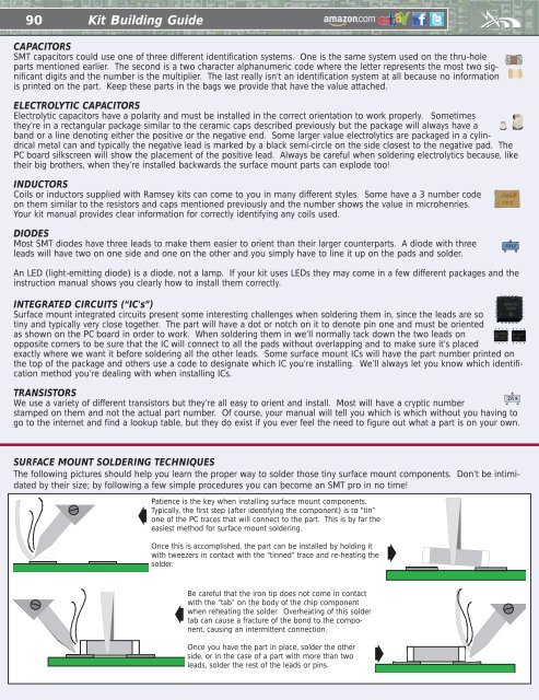
SURFACE MOUNT SOLDERING TECHNIQUES<br />
The following pictures should help you learn the proper way to solder those tiny surface mount components. Don’t be intimidated<br />
by their size; by following a few simple procedures you can become an SMT pro in no time!<br />
➧<br />
Patience is the key when installing surface mount components.<br />
Typically, the first step (after identifying the component) is to “tin”<br />
one of the PC traces that will connect to the part. This is by far the<br />
easiest method for surface mount soldering.<br />
Once this is accomplished, the part can be installed by holding it<br />
with tweezers in contact with the “tinned” trace and re-heating the<br />
solder.<br />
➧<br />
Be careful that the iron tip does not come in contact<br />
with the “tab” on the body of the chip component<br />
when reheating the solder. Overheating of this solder<br />
tab can cause a fracture of the bond to the component,<br />
causing an intermittent connection.<br />
Once you have the part in place, solder the other<br />
side, or in the case of a part with more than two<br />
leads, solder the rest of the leads or pins.<br />
➧<br />
➧