OPERATING INSTRUCTIONS - Eijkelkamp Agrisearch Equipment
OPERATING INSTRUCTIONS - Eijkelkamp Agrisearch Equipment
OPERATING INSTRUCTIONS - Eijkelkamp Agrisearch Equipment

Create successful ePaper yourself
Turn your PDF publications into a flip-book with our unique Google optimized e-Paper software.
© September 2006<br />
<strong>OPERATING</strong> <strong>INSTRUCTIONS</strong><br />
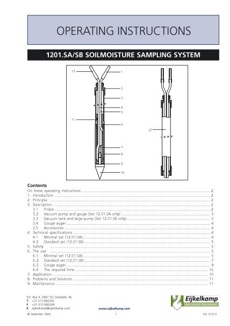
1201.SA/SB SOILMOISTURE SAMPLING SYSTEM<br />
12<br />
11<br />
1<br />
1<br />
2<br />
3<br />
4<br />
5<br />
Contents<br />
On these operating instructions ....................................................................................................................... 2<br />
1. Introduction ................................................................................................................................................ 2<br />
2. Principle .................................................................................................................................................... 2<br />
3. Description.................................................................................................................................................. 2<br />
3.1 Probe ................................................................................................................................................ 2<br />
3.2 Vacuum pump and gauge (Set 12.01.SA only) .................................................................................. 3<br />
3.3 Vacuum tank and large pump (Set 12.01.SB only) ............................................................................. 3<br />
3.4 Gouge auger ..................................................................................................................................... 4<br />
3.5 Accessories ....................................................................................................................................... 4<br />
4. Technical specifications ............................................................................................................................... 4<br />
4.1 Minimal set (12.01.SA) ..................................................................................................................... 4<br />
4.2 Standard set (12.01.SB) .................................................................................................................... 5<br />
5. Safety .................................................................................................................................................... 5<br />
6. The use .................................................................................................................................................... 5<br />
6.1 Minimal set (12.01.SA) ..................................................................................................................... 5<br />
6.2 Standard set (12.01.SB) .................................................................................................................... 7<br />
6.3 Gouge auger ..................................................................................................................................... 9<br />
6.4 The required time ........................................................................................................................... 10<br />
7. Application ................................................................................................................................................ 10<br />
8. Problems and Solutions ............................................................................................................................. 11<br />
9. Maintenance ............................................................................................................................................. 11<br />
P.O. Box 4, 6987 ZG Giesbeek, NL<br />
T +31 313 880200<br />
F +31 313 880299<br />
E eijkelkamp@eijkelkamp.com<br />
6<br />
7<br />
8<br />
9<br />
10<br />
www.eijkelkamp.com<br />
27<br />
M2.12.01.E
On these operating instructions<br />
<br />
!<br />
text<br />
When the symbol shown on the left is placed before a piece of text, this means that an important<br />
instruction follows.<br />
When the symbol shown on the left is placed before a piece of text, this means that an important<br />
warning follows pointing out a risk of injury to the user or damage to the device.<br />
Text in italics means that the actual text is shown on the display screen.<br />
1. Introduction<br />
To obtain a water sample out of a well drained zone, which is above the ground water level is very complicated.<br />
This is caused as the water is attached to the soil. With direct methods a soil sample will be taken to the<br />
laboratory in order to withdraw the soil moisture.<br />
The soil moisture sampler operates according to the direct method, on which the moisture will be withdrawn<br />
direct and undiluted. The advantage of this method is that you get an undiluted water sample. Another benefit<br />
is that you do not need to bring large quantities of soil material to the laboratory.<br />
This manual describes the following two soil moisture sampling systems:<br />
Minimal set for singular sampling up to a depth of 1.5m (12.01.SA)<br />
Standard set for multiple sampling up to a depth of 1.5m (12.01.SB)<br />
2. Principle<br />
Both sets operate according to the same principle. A small porous water<br />
accepting pipe, after first saturating it water, is placed into the soil. By<br />
creating a under pressure on the inside (by a vacuum pump or tank), the<br />
soil moisture will be sucked in.<br />
A wet pipe will not transmit air as long as it has not reached its bubbling<br />
pressure point. The bubbling pressure point is the moment on which<br />
adhesion between water and ceramic material and the largest pore<br />
breaks. The pressure point of the ceramics will not be reached in<br />
practice.<br />
3. Description<br />
3.1 Probe<br />
The probe is constructed as following:<br />
A stainless steel tube (3) is on the bottom fitted with a synthetic core(7)<br />
which is fixed by a screw(11). Around this core there is a porous ceramic<br />
cylinder (8) which is held on its place by a synthetic cone (10). The<br />
silicone rings (6 & 9) will provide an air tight seal.<br />
Through the boring of the core two flexible tubes are lead. A Teflon tube<br />
(4) reaches Until the bottom of the porous cylinder and is provided with a<br />
amber coloured connection tube (12) on the top. A nylon tube (5) ends<br />
above the cylinder is provided with a transparent connection tube(1).<br />
If you have doubt (about the colour) which one is Teflon, you can use a<br />
match or a lighter to check it; Nylon will melt easily, Teflon however only<br />
when heated long.<br />
In order to connect extension rods, the top of the tube is provided with screw-thread (2).<br />
2
After the probe is inserted into the soil and the connection of the ceramic cylinder (8) against the soil is correct,<br />
a vacuum will be created by a pump, through the tube (12).<br />
From this moment the nylon tube (1) has to be squeezed air tight by the pinch clamp. Now soil moisture will be<br />
sucked in, which is less strongly attached to the soil than the under pressure in the sampler. The gathered<br />
moisture in the sampler can be extracted by releasing the pinch clamp on the nylon tube (1 ). The sample is<br />
collected by placing a sample bottle between probe and vacuum source.<br />
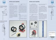
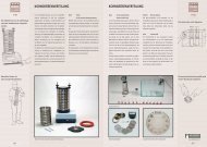
3.2 Vacuum pump and gauge (Set 12.01.SA only)<br />
The set for singular sampling (12.01.SA) is provided with a small and light manual pump (13) with gauge(14).<br />
With this set only one probe at a time can be connected. A sample bottle is used as a buffer for the vacuum.<br />
14<br />
13<br />
19 20<br />
Vacuüm pump and manometer (set 12.01.SA) Vacuüm tank and large pump (set 12.01.SB)<br />
3.3 Vacuum tank and large pump (Set 12.01.SB only)<br />
The standard set for maximal 5 fold sampling is equipped with a large pump (15) and a vacuum tank (16). The<br />
Gauge (17) indicates the under pressure within the tank. The vacuum tank has rubber stop with 5 connections<br />
(8) which can be connected to the same quantity of probes. The vacuum is created by the manual pump(15).<br />
The non return valve (19) and shut-off valve(20) prevents entering of air via the pump, when there is vacuum in<br />
the tank. Due to the large vacuum reserve, the set B can operate for a longer time frame without the necessity<br />
of monitoring. Within a radius of 2 meter, can be sampled with 5 probes with its own sample bottle,<br />
connected to the tank through the stop (18) simultaneously.<br />
3<br />
15<br />
17<br />
18<br />
16
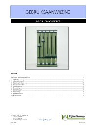
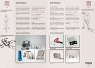
3.4 Gouge auger<br />
The auger body fo the gouge auger (21) is almost half cylindrical, with parallel cutting faces from top to bottom.<br />
The diameter is 30mm. The maximal length of the sample is 50 cm. The auger can be extended by<br />
connecting a coupling sleeve(23) and extension rod(22) (set 12.01.SB only) onto the upper piece (24).<br />
Extension rod (left) and coupling sleeve (right)<br />
Gouge auger<br />
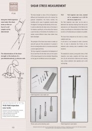
3.5 Accessories<br />
Push-/pull handle<br />
The push-/pull handle exists out of 2 parts which can be connected<br />
around a rod. Due to its shape the push/pull hand will clamp itself<br />
onto a rod as long a force is exercised on both handles.<br />
Utility probe (Set 12.01.SB ONLY)<br />
The glass fibre utility probe has a length of 105cm and has a cone of a diameter of 19mm. The utility probe is<br />
isolated and can be used, even in very dry soils, to look for cables and tubes.<br />
Hanging clamp (Set 12.01.SB ONLY)<br />
The hanging clamp is placed on the probe or extension tube and fixed by screws. Two separate clamping jaws<br />
will enable you to position the sample bottle accurately.<br />
4. Technical specifications<br />
4.1 Minimal set (12.01.SA)<br />
Part Description<br />
Insert probe Length 50cm, Ø 18 mm.<br />
Ceramic cup Purity of 99,8% Al 2 O 3<br />
Extension tube Stainless Steel, length 100 cm, 2 inner hoses<br />
Sample bottle 250 cc met glass stopper<br />
Gouge Ø 30 mm, bayonet connection<br />
Teflon hose Ø 2 x 4 mm, length 10 m<br />
Carrying bag Inner dimensions: 17 x 150 cm, with 2 shoulder straps.<br />
22<br />
21<br />
4<br />
26<br />
Push-/Pull handle<br />
23
4.2 Standard set (12.01.SB)<br />
Part Description<br />
Insert probe Length 50cm, Ø 18 mm.<br />
Ceramic cup Purity of 99,8% Al 2 O 3<br />
Extension tube Stainless Steel, length 100 cm, 2 inner hoses<br />
Sample bottle 250 cc met glass stopper<br />
Gouge Ø 30 mm, bayonet connection<br />
Extension rods length 100 cm, bayonet connection, fit for gouge auger<br />
Utility probe Glass fibre, length 105 cm.<br />
Aluminium case suitable for 10 sample bottles<br />
Aluminium box transport box, outer dimensions: 108x23x14 cm<br />
Vacuum tank with pump suitable for 5 insertion probes, content 6.7 litre, inclusive 10 m connection hose.<br />
5. Safety<br />
!<br />
!<br />
!<br />
!<br />
!<br />
!<br />
Be cautious during a thunderstorm. Lightning strokes often occur in the open field, in<br />
particular when holding a metal auger.<br />
To withdraw the auger keep your back straight and your knees bent to prevent injuries.<br />
Empty the gouge auger with a spatula. Make sure not to touch the cutting edges; they are<br />
very sharp. Inappropriate use may cause you to cut your hands.<br />
Prior to augering use the utility probe to check for cables, tubes and pipes. If necessary, select<br />
another spot to auger.<br />
Fill the borehole with soil or special bentonite plugs after augering. This will prevent humans<br />
or animals to trip into the hole and incur injuries. In addition, it will allow impermeable soil<br />
layers to recover.<br />
Be cautious during a thunderstorm. Lightning strokes often occur in the open field, in<br />
particular when holding a metal auger.<br />
6. The use<br />
6.1 Minimal set (12.01.SA)<br />
1. Prepare the probe one or several days before the actual installation in the field. That is to say that the<br />
ceramic cup has to be saturated with gas free water. You can do this by the following method:<br />
Take distilled water and boil this on order to remove the dissolved gasses and let it cool down.<br />
Take distilled water, pour it in a glass bottle and bring it under vacuum. The dissolved gasses will come<br />
out within minutes.<br />
2. Place the ceramic part of the probe complete under water, squeeze the amber coloured hose (12) tight with<br />
a hose clamp, connect the vacuum pump onto the other hose and create a vacuum until water is coming out<br />
of the hose. Now all pores are filled with water. In order to protect the cup against dry out and bumps, wrap<br />
some polyethylene, aluminium or a clean wet cloth around it.<br />
5
3. Appoint the place and depth where the sampling has to take place.<br />
!<br />
!<br />
Check before boring for any (electricity) cables, conduits or pipes in the<br />
ground (check the local municipally). Use the optional obtainable<br />
utility probe for checking the boring site safely. If there are, choose<br />
another place.<br />
Be careful during thunderstorms; in open fields the risk of being struck by<br />
Lightning is higher with a metal object (auger) in your hand.<br />
4. Bore a hole with the gouge auger up to just above sample depth (see § 6.3)<br />
!<br />
!<br />
!<br />
Do not use any force to hammer the gouge auger into the soil; you might<br />
be damaging the tools.<br />
In order to prevent back troubles, retract the auger with a straight back<br />
and bent knees.<br />
To discharge the gouge with a spatula, beware not to abrade your fingers/<br />
hand on the cutting edges. These edges are sharp and can inflict cuts.<br />
Wear sturdy gloves<br />
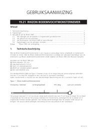
5. Mark the probe for sampling on the desired depth.<br />
Probe installation<br />
6
6. Place the probe in the hole and push it, with help of the push/pull handle (26), carefully up to the desired<br />
depth. The contact between the ceramic part and the soil has to be optimal. Option wise the probe can be<br />
extended; connect the hoses of the probe to the same tubes of the extension piece and screw the<br />
extension piece (27) on the probe.<br />
7. Connect the amber coloured connection hose (12) to the rubber stopper of the sample bottle by means of<br />
the supplied teflon hose.<br />
8. squeeze the transparent hose (1) of the probe tight with a pinch clamp.<br />
9. Remove the rubber cone on the “suction side” of the vacuum pump (13).<br />
10.Connect the other outlet of the rubber stopper to the vacuum pump (13).<br />
11.Take out the air out of the system by means of the vacuum pump (13)<br />
12.Now under pressure is created in the sample system. Soil moisture will be sucked in through porous wall of<br />
the ceramic part (8) into the sample tube. If the contact between the soil and the probe is poor, less water<br />
per time unit will be the yield. The enormous adhesion between the water and ceramics will prevent<br />
entering air into the system. Therefore check the pressure gauge just after creating the vacuum: if the<br />
pressure is decreasing fast, then there must be a leakage or a crack the ceramic part.<br />
13.Optional the vacuum pump (13) can be removed, after the connection hose between the pump and the<br />
sample bottle is squeezed tight; the bottle now functions as a vacuum storage.<br />
14.When sufficient soil moisture is sampled, the probe can be emptied by releasing the transparent silicone<br />
hose of the probe from its pinch clamp. The atmospheric pressure (= 1 atmosphere) will force the water<br />
within the porous part through the teflon hose into the sample bottle.<br />
15.Just after the sample is taken, the sample bottle will be closed with a rubber stopper and stored in the case<br />
with foam rubber upholstery.<br />
16.Extract te probe with the push/pull handle.<br />
!<br />
After boring fill the hole with bored out material or with special betonite plugs. This prevents<br />
that men and animal will step into the hole and get injured. Moreover impermeable soil layers<br />
will be restored.<br />
17.After use clean the probe thoroughly by using a brush, rinse the probe well with tap water and after<br />
cleaning store it dry. If the probe will be used within the next days then wrap it in a foil or a wet cloth to<br />
prevent drying out.<br />
6.2 Standard set (12.01.SB)<br />
1. Prepare the probe one or several days before the actual installation in the field. That is to say that the<br />
ceramic cup has to be saturated with gas free water. You can do this by the following method:<br />
Take distilled water and boil this on order to remove the dissolved gasses and let it cool down.<br />
Take distilled water, pour it in a glass bottle and bring it under vacuum. The dissolved gasses will come<br />
out within minutes.<br />
2. Place the ceramic part of the probe complete under water, squeeze the amber coloured hose (12) tight with<br />
a hose clamp, connect the vacuum pump onto the other hose and create a vacuum until water is coming out<br />
of the hose. Now all pores are filled with water. In order to protect the cup against dry out and bumps, wrap<br />
some polyethylene, aluminium or a clean wet cloth around it.<br />
3. Appoint the place and depth where the sampling has to take place.<br />
!<br />
!<br />
Check before boring for any (electricity) cables, conduits or pipes in the ground (check the<br />
local municipally). Use the optional obtainable utility probe for checking the boring site<br />
safely. If there are, choose another place.<br />
Be careful during thunderstorms; in open fields the risk of being struck by lightning is higher<br />
with a metal object (auger) in your hand.<br />
7
4. Bore a hole with the gouge auger up to just above sample depth (see § 6.3)<br />
!<br />
!<br />
!<br />
Do not use any force to hammer the gouge auger into the soil; you might be damaging the<br />
tools.<br />
In order to prevent back troubles, retract the auger with a straight back and bent knees.<br />
To discharge the gouge with a spatula, beware not to abrade your fingers/hand on the cutting<br />
edges. These edges are sharp and can inflict cuts. Wear sturdy gloves<br />
5. Mark the probe for sampling on the desired depth<br />
6. Place the probes into the different holes and push it, with help<br />
of the push/pull handle (26), carefully up to the desired depth.<br />
The contact between the ceramic part and the soil has to be<br />
optimal. Option wise the probe can be extended; connect the<br />
hoses of the probe to the same tubes of the extension piece<br />
and screw the extension piece (27) on the probe.<br />
7. Connect the amber coloured connection hoses (12) to the<br />
rubber stopper of the matching sample bottle by means of the<br />
supplied teflon hose. Option wise you can fit the hanging<br />
clamp with sample bottle on to the probe.<br />
8. Squeeze the other transparent hose (1) of the probe tight with<br />
a pinch clamp.<br />
9. Connect the second hose of each sample bottle to the vacuum<br />
tank. Make sure to push the rubber stopper firmly for a good<br />
seal<br />
10.Close the not used hoses of the rubber stopper (18) with a<br />
pinch clamp.<br />
11.Open the shut-off valve(20) of the vacuum tank (16) and<br />
create a vacuum of ± 0,7 bar by pumping. Next, close the shut<br />
off valve (20) to prevent leakage along the pump.<br />
12.Now under pressure is created in the sample system. Soil<br />
moisture will be sucked in through porous wall of the ceramic part (8) into the sample tube. If the contact<br />
between the soil and the probe is poor, less water per time unit will be the yield. The enormous adhesion<br />
between the water and ceramics will prevent entering air into the system. Therefore check the pressure<br />
gauge just after creating the vacuum: if the pressure is decreasing fast, then there must be a leakage or a<br />
crack the ceramic part.<br />
13.When sufficient soil moisture is sampled, the probe can be emptied by releasing the transparent silicone<br />
hose (1)of the probe from its pinch clamp. The atmospheric pressure (= 1 atmosphere) will force the water<br />
within the porous part through the teflon hose into the sample bottle.<br />
14.Just after the sample is taken, the sample bottle will be closed with a rubber stopper and stored in the case<br />
with foam rubber upholstery.<br />
15.Extract te probe with the push/pull handle.<br />
!<br />
After boring fill the hole with bored out material or with special betonite<br />
plugs. This prevents that men and animal will step into the hole and get injured. Moreover<br />
impermeable soil layers will be restored.<br />
16.After use clean the probe thoroughly by using a brush, rinse the probe well with tap water and after<br />
cleaning store it dry. If the probe will be used within the next days then wrap it in a foil or a wet cloth to<br />
prevent drying out.<br />
8
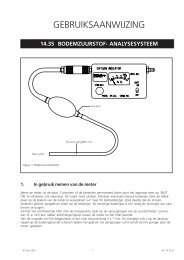
6.3 Gouge auger<br />
1. Screw the synthetic handle (25) in the upper part (24)<br />
2. Connect the auger parts (see below drawing). Attach the optional obtainable<br />
extension rods during deeper augerings only on the up side of the auger,<br />
directly under the upper part. When dismantling attaching it is import to maintain<br />
the original sequence (the rods have a certain curve which is uphold in the bore hole<br />
3. Press the gouge auger vertically, without turning, into the soil. Take samples of<br />
Maximal 50 cm. When the auger meets a lot of resistance, you can overcome this by<br />
Giving it a turn. Then press it further down.<br />
4. If the gouge is full, turn it and extract it with a slight turn. Cut off the cylindrical<br />
material up to the cutting edges by using the bent spatula (see figure right above).<br />
The left material is an almost undisturbed profile. It is possible to bring on marks with<br />
the spatula each 10 cm by means of the measuring marks on the outside of the<br />
gouge auger.<br />
!<br />
!<br />
!<br />
Do not use any force to hammer the gouge auger into the soil; you might be damaging the<br />
tools.<br />
In order to prevent back troubles, retract the auger with a straight back and bent knees.<br />
To discharge the gouge with a spatula, beware not to abrade your fingers/hand on the cutting<br />
edges. These edges are sharp and can inflict cuts. Wear sturdy gloves<br />
Coupling an auger<br />
1 2 3<br />
4<br />
9
6.4 The required time<br />
The required time which is necessary to sample a certain quantity of soil moisture depends on several aspects,<br />
among others:<br />
the moisture content of the soil<br />
The amount of vacuum pressure within the system<br />
The permeability of the porous element<br />
The number of probes connected to the bottle<br />
The required time for sampling 100 cc soil moister may vary between 20 minutes up to 10 hours. Optional a<br />
seal around the stainless steel can be provided to prevent entering of rain water, which affect the results. Tests<br />
have made out that out of the most soils at field capacity at least 15 cc per hour can be sampled.<br />
The limit value where no moisture can be sampled is about 30-40% below field capacity (pF 2,0). As the soil is<br />
dryer, an increase of the vacuum has a positive influence on the result of the moisture withdraw.<br />
7. Application<br />
with the soil moisture sampler moisture can be withdrawn out of the unsaturated zone.<br />
Soil moisture samples are taken for determination of:<br />
The salt concentration in the soil moisture<br />
The concentration of certain chemicals in the soil moisture (e.g. nitrate)<br />
· The wash away/down of different elements<br />
Remark: Please bear in mind that ceramics can absolve certain chemicals in more or less amounts.<br />
The representativeness of the sample gathered with ceramic soil moisture samplers can be qualified<br />
as following:<br />
Spore elements: please be very careful in connection to ion exchange en sorption<br />
Macro parameters: be careful. Will fulfil nitrate analysis<br />
Organic parameter: handle with care<br />
pH: handle with care<br />
Naturally a certain saturation will take place. However it is not possible to give a prognoses. Besides agricultural<br />
purposes, the probes can be use for sampling of amongst others percolation water at refuse dumps, flush water<br />
of roads (control of slipperiness).<br />
In case of frequent sampling on the same spot, it is recommendable to place a permanent probe. To maintain<br />
the speed and reliability of the samples, it is advisable to connect multiple probes on one sample bottle. In this<br />
case more connection possibilities to the bottle has to be provided.<br />
A permanent line-up with multiple probes on one bottle gives the following advantages:<br />
fast sampling<br />
no repeating damage of plant roots<br />
the soil moisture is always extracted on the same spot<br />
10
8. Problems and Solutions<br />
In case a ceramic element (8) is damaged, it has to be replaced. Release the synthetic cone (10) from the<br />
probe, replace the element (8) en mount the cone again. The O-rings (6) and (9) has to be on its place<br />
9. Maintenance<br />
Because you do not want that a residue of a soil sample influence another sample, it is desired, before<br />
conducting a next sampling, to rinse the porous element and the teflon hose of the probe and perhaps the<br />
extension part with distilled water. This can be done by creating a minor vacuum, whilst the probe is placed<br />
in a bottle with distilled water.<br />
Nothing in this publication may be reproduced and/or made public by means of print, photocopy, microfilm or any other means without previous<br />
written permission from <strong>Eijkelkamp</strong> <strong>Agrisearch</strong> <strong>Equipment</strong>.<br />
Technical data can be amended without prior notification.<br />
<strong>Eijkelkamp</strong> <strong>Agrisearch</strong> <strong>Equipment</strong> is interested in your reactions and remarks about its products and operating instructions.<br />
11