Tensior T8 - Eijkelkamp Agrisearch Equipment
Tensior T8 - Eijkelkamp Agrisearch Equipment
Tensior T8 - Eijkelkamp Agrisearch Equipment

You also want an ePaper? Increase the reach of your titles
YUMPU automatically turns print PDFs into web optimized ePapers that Google loves.
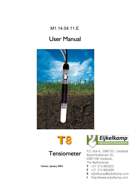
User Manual<br />
<strong>T8</strong><br />
Tensiometer<br />
Version January 2003<br />
<strong>T8</strong><br />
P.O. Box 4, 6987 ZG Giesbeek<br />
Nijverheidsstraat 30,<br />
6987 EM Giesbeek,<br />
The Netherlands<br />
T +31 313 880200<br />
F +31 313 880299<br />
E eijkelkamp@eijkelkamp.com<br />
I http://www.eijkelkamp.com
Foreword<br />
The success of any technical system is directly depending on a correct<br />
operation. Moreover, the systems must be reliable, durable and require a<br />
minimum of maintenance to achieve target-directed results and keep the<br />
servicing low.<br />
At the beginning of a measuring task or research project the target, all effective<br />
values and the surrounding conditions must be defined. This leads to the<br />
demands for the scientific and technical project management which describes<br />
all quality related processes and decides on the used methods, the technical<br />
and measurement tools, the verification of the results and the modelling.<br />
The continuously optimised and synergic correlation of all segments and it's<br />
quality assurance are finally decisive for the success of a project.<br />
Thus, I would be pleased to receive your critiques and appraisals.<br />
München, 30.09.2002<br />
3
Table of contents<br />
1 Content of delivery ....................................................................................7<br />
2 Short instructions .......................................................................................7<br />
3 Safety notes................................................................................................9<br />
4 Description of the <strong>T8</strong>...............................................................................10<br />
4<br />
4.1 Output signals.....................................................................................10<br />
4.2 Sensor body........................................................................................10<br />
4.2.1 Pressure sensor.........................................................................10<br />
4.2.2 Temperature sensor .................................................................11<br />
4.2.3 IR indicator................................................................................11<br />
4.3 The ceramic cup .................................................................................12<br />
5 Refilling.....................................................................................................13<br />
5.1 When does the Tensiometer needs to be refilled?.............................13<br />
5.2 Refilling in the lab................................................................................13<br />
5.3 Refilling in the field..............................................................................15<br />
5.4 Refilling with vacuum ..........................................................................16<br />
6 Calibration................................................................................................18<br />
6.1 Checking the offset.............................................................................18<br />
6.2 Offset correction for non horizontal installations...............................19<br />
6.3 Correlation of water column and pressure ........................................19<br />
7 Concept and installation...........................................................................20<br />
7.1 Selecting the measuring site................................................................20<br />
7.2 Selecting the installation angle ............................................................20<br />
7.2.1 "Vertical" with downwardly angle .............................................20<br />
7.2.2 "Horizontally" with upwardly angle ...........................................20
7.3 Number of Tensiometers per level ....................................................21<br />
7.4 Extend of the measuring site ..............................................................21<br />
7.5 Length of the refilling tubes ................................................................22<br />
7.6 Jacket tubes.........................................................................................22<br />
7.7 Ideal condition for installation.............................................................22<br />
7.8 Documentation...................................................................................23<br />
7.9 Installation...........................................................................................23<br />
8 Connecting the <strong>T8</strong> ...................................................................................25<br />
8.1 Single-ended or differential application...............................................25<br />
8.2 Connecting the IR-indicator................................................................26<br />
8.3 Wire specifications..............................................................................26<br />
9 Protecting the measuring site...................................................................27<br />
9.1 Theft and vandalism............................................................................27<br />
9.2 Frost ...................................................................................................27<br />
9.3 Lightning .............................................................................................27<br />
10 Additional notes..................................................................................29<br />
10.1 Interpretation and maximum measuring range..............................29<br />
10.2 Osmosis .........................................................................................30<br />
10.3 Emptying the <strong>T8</strong> ............................................................................30<br />
11 Accessories .........................................................................................31<br />
11.1 Connecting and extension cables...................................................31<br />
11.2 Handheld measuring device ...........................................................31<br />
11.3 Augers............................................................................................31<br />
11.4 Refill- and calibration kits ...............................................................32<br />
12 Contact and communication...............................................................33<br />
13 Technical specifications.......................................................................34<br />
5
1 Content of delivery<br />
The delivery of a <strong>T8</strong> includes:<br />
• Tensiometer, calibrated and filled, cable with plug and protective cap<br />
• This manual<br />
• Plastic bottle protecting the ceramic cup, must be filled to half with<br />
water to keep the cup moist<br />
• Shaft water protection disk<br />
• Calibration certificate with technical data and output signals<br />
Available accessories: see chapter "Accessories"<br />
If you wish to receive a individual calibration certificate for each Tensiometer,<br />
please contact us and give us the serial number of the Tensiometers.<br />
2 Short instructions<br />
Please read and understand the complete manual prior to first use.<br />
In general, the <strong>T8</strong> is filled and ready for installation when supplied.<br />
For installation proceed as follows:<br />
1. Drilling the borehole: An installation angle of 25° to 65° from the vertical<br />
line is ideal for the optimal removal of air from the cup. Mark the required<br />
drilling depth on the auger and on the Tensiometer shaft.<br />
Note: Installation depth = drilling depth / cos α<br />
Drill a borehole, diameter 25 mm, with the required depth. offers<br />
special Tensiometer gouge augers with shaped blade tip.<br />
2. Illuvation of the cup is only needed in clayey soils and only if the borehole is<br />
larger than the diameter of the cup (which is 24 mm). With the special<br />
Tensiometer gouge auger illuvation is unnecessary. In coarse sand and<br />
7
pebbly grounds a fine grained illuvation paste would even effect a water<br />
reservoir which would slow down the response.<br />
3. Take off the protective plastic bottle from the Tensiometer cup. Pull the<br />
bottle it off carefully or slowly turn it counter-clockwise!<br />
4. Insert the <strong>T8</strong> into the borehole up to the depth mark without using force.<br />
In clayey soils an overpressure might develop: Check the Tensiometer's<br />
pressure reading with an Infield measuring device or a datalogger!<br />
8<br />
Important: Pay attention to the engraved black spot on the<br />
end of the shaft that marks the position of the exit opening of<br />
the external filling inside the cup:<br />
a) Downwards installation: If the position of the cup will be<br />
lower than the end of the shaft, this mark must point<br />
upwards!<br />
b) Upwards installation: If the position of the cup<br />
will be higher than the end of the shaft, this mark<br />
must point downwards!<br />
5. Push down the shaft water retaining disk to a position directly on the soil<br />
surface. Water flowing down the shaft will not disturb measurements.<br />
6. Leave on the protective cap on the plug if the plug is not connected.<br />
7. Connect the Tensiometer signal wires as specified (see chapter 8<br />
Connecting the <strong>T8</strong>). If the measuring station is prepared , attach<br />
the Tensiometer plug to the suitable connecting cable.<br />
Notes:<br />
- The less air is inside the cup and the better the soil's conductivity is, the faster<br />
the Tensiometer will respond.<br />
- If the soil is dryer than 900 hPa, it does not make sense to refill the<br />
Tensiometer. Refill the Tensiometer as soon as the Tensiometer that is
installed in the next lower level has reached the reading when the upper<br />
Tensiometer had dried out.<br />
3 Safety notes<br />
Tensiometer are instruments for measuring the soil water tension, soil water<br />
pressure and soil temperature and are designed for this purpose only.<br />
Caution<br />
Lightning: Long cables act as antennas and might conduct surge voltage in<br />
case of lightning stroke – this might damage sensors and instruments.<br />
Caution<br />
Frost: Tensiometers are filled with water and therefore, are sensitive to<br />
frost! In wintertime, do not leave Tensiometers inside your car overnight.<br />
Generally, frost should not harm Tensiometers installed in depths below<br />
30 cm.<br />
Caution<br />
Overpressure: The non destructive maximum pressure is 3000 hPa. Higher<br />
pressure, which might occur for example during insertion in wet clayey<br />
soils or triaxial vessels, will destroy the pressure sensor! The applied<br />
pressure should not exceed 2000 hPa!<br />
Caution<br />
Electronics: Any electrical installations should only be executed by qualified<br />
personnel!<br />
Caution<br />
Ceramic cup: Avoid to touch the cup with your fingers. The ceramic<br />
should not have contact with grease or soap as this will influence the<br />
hydrophilic performance.<br />
9
4 Description of the <strong>T8</strong><br />
4.1 Output signals<br />
The <strong>T8</strong> is optimised for in-the-field use. Signals for soil water tension, soil<br />
temperature and filling status are offered.<br />
Water tension and temperature are linear voltage signals 0 ... 2 V. Thus, the<br />
signals are directly connectable to nearly any datalogger or other data<br />
recording device.<br />
The IR indicator works like a switch so the filling status can have two levels:<br />
"0V" (switch is open) for correct filling, or Vin = power supply voltage (switch<br />
is closed) if the Tensiometer needs to be refilled.<br />
4.2 Sensor body<br />
The complete electronic of the <strong>T8</strong> is integrated in the sensor body. The<br />
housing consists of glass-fibre reinforced synthetic. All electronic parts are<br />
completely covered with epoxy resin - the optimal and everlasting protection<br />
against moisture.<br />
The <strong>T8</strong> is calibrated electronically by<br />
programmable potentiometers. The calibration is<br />
stored in EPROM's.<br />
4.2.1 Pressure sensor<br />
The piezoelectric pressure sensor measures the soil water tension against the<br />
atmospheric pressure. The atmospheric pressure is conducted through a<br />
watertight diaphragm (the white, 2 cm long tube on the cable) and through the<br />
cable to the reference side of the pressure sensor.<br />
The non destructive maximum pressure is 3.000 hPa. Higher pressure will<br />
damage the sensor and absolutely must be avoided!<br />
10<br />
Sensors and refilling tube on sensor body
4.2.2 Temperature sensor<br />
A Pt1000 1/3 DIN B is used as temperature sensor. The Pt1000 has a<br />
maximum deviation of ±0.1 K at 0°C.<br />
The tip of the sensor dips into the Tensiometer cup's water. Thus, the best<br />
possible thermal contact to the soil is achieved.<br />
The correlation of water tension/water content is temperature depended. The<br />
influence is low with water tensions from 0 … 100 hPa ⇒ 0 … 6 hPa/K, but<br />
with tensions over 1000 hPa it is:<br />
Ψ = (R T/M) ln p/po Ψ = water tension R = gas constant (8,31J/mol K)<br />
M = molecular weight p = vapour pressure<br />
po = saturation vapour pressure at soil temperature<br />
(see vapour pressure tables by Scheffler/Straub, Grigull)<br />
4.2.3 IR indicator<br />
With the IR indicator the filling status of a <strong>T8</strong> in a downwardly installation can<br />
be checked without removing the Tensiometer from the soil.<br />
If the Tensiometer is installed in an upwardly angle (cup is higher than the<br />
end of the shaft), the indicator will react not before the cup is almost<br />
completely empty.<br />
Measuring principle of the IR indicator: A photo-sensor and a source of IR-light<br />
are integrated in the <strong>T8</strong> body. If there is only water between source and sensor<br />
the absorption is high and the photo-sensor will not respond. If there should be<br />
a bubble in-between, the measured light intensity arises and the electronic will<br />
switch to the high output signal, indicating the need to refill. The IR-"switch"<br />
can be burdened with 50 mA. LEDs or relays can be connected.<br />
Benefits of the IR indicator are an optimal service: If for example mounting rails<br />
with integrated LEDs are used, the user can check at a glance if all<br />
Tensiometers work well or which need to be refilled.<br />
11
Also, for quality assurance, the status of the signal can be logged for later<br />
evaluation of the readings.<br />
4.3 The ceramic cup<br />
Avoid to touch the cup with your fingers. The ceramic should not have<br />
contact with grease or soap as this will influence the hydrophilic<br />
performance.<br />
To transfer the soil water tension as a negative pressure into the Tensiometer,<br />
a semi-permeable diaphragm is required. This must have good mechanical<br />
stability and water-permeability, but also have gas impermeability.<br />
The <strong>T8</strong> cup consists of ceramic Al2O3 sinter material. The special<br />
manufacturing process guarantees homogeneous porosity with good water<br />
conductivity and very high firmness. Compared to conventional porous ceramic<br />
the cup is much more durable.<br />
The bubble point is higher than 6000 hPa. If the soil is dryer than 6000 hPa the<br />
negative pressure inside the cup decreases and the readings go down to 0 hPa.<br />
With these characteristics this material has outstanding suitability to work as<br />
the semi permeable diaphragm for Tensiometers.<br />
4.4 Reference air pressure<br />
The reference atmospheric air pressure is conducted to the pressure<br />
transducer via the air permeable (white) Teflon membrane and through the<br />
cable. The membrane does not absorb water. Water will not pass through the<br />
membrane into the cable, but condensed water inside the cable will leave the<br />
cable through the membrane.<br />
The white membrane on the cable must always have contact to air and<br />
should never be submersed into water.<br />
12
5 Refilling<br />
To assure a rapid and reliable measurement of the soil water tension, the cup<br />
must possibly be filled with de-ionised and degassed water and without bubbles<br />
of air. After dry periods or periods with a large number of wet and drying out<br />
successions, the <strong>T8</strong> must be refilled.<br />
For all refilling methods, the following items are always required:<br />
- Syringe with valve<br />
- Degassed, de-ionised water<br />
- Measuring device for Tensiometer pressure signal<br />
5.1 When does the Tensiometer needs to be refilled?<br />
The Tensiometer needs to be refilled:<br />
a, For Tensiometers installed "downwardly", the IR indicator will light up.<br />
b, If no signal peaks show up anymore.<br />
c, Tensiometers should not be refilled until the soil is moister than 900 hPa.<br />
If the soil gets dryer than 805 hPa, the readings will stop at the vapour pressure<br />
of water (i. e. 927 hPa at 20°C and atmospheric pressure of 950 hPa). By<br />
diffusion and slight leakage the reading will slowly drop within months.<br />
Still, if the soil dries out more than 6000 hPa, the negative pressure will drop<br />
much faster as air will enter the cup.<br />
5.2 Refilling in the lab<br />
To reach a measuring range of 900 hPa the Tensiometers should be refilled in<br />
the laboratory. With this refilling method a measuring range up to approx. 900<br />
hPa can be achieved (at 1013 hPa atmospheric pressure). A refill kit is required.<br />
Degassing procedure:<br />
1, Set up the refilling kit and connect the vacuum pump. The pump should<br />
achieve at least 30 hPa against vacuum (approx. 930 hPa).<br />
13
2, Unscrew the cup in clockwise direction and empty it. Do not touch the<br />
ceramic cup with your fingers. Wrap a clean towel around the cup.<br />
The pressure sensor diaphragm is inside the small boring on the pressure<br />
sensor body. It is very sensitive and may never be touched! It can be<br />
destroyed even by slightest contact! No contamination should get on the<br />
sealing and gasket.<br />
3, If the cup is drained it should be drenched in distilled water overnight by<br />
placing it in a beaker filled with water.<br />
Important: There should be no water inside the cup. The cup must be in an<br />
upright position so only the cup's outside is covered with water. Otherwise<br />
cavities of air might be enclosed inside the ceramic.<br />
4, The drenched cup should be empty. Insert the cup to the adapter and<br />
connect it to the degassing device. Place the cup in water in an upright<br />
position as described above.<br />
5, Fill the other adapter capsule to the half with water and insert the<br />
sensor body. Connect the adapter to the degassing device as well.<br />
6, Start the vacuum pump. With drenched cups, the procedure will take 4 to 5<br />
hours. From time to time, tap on cup and sensor body to loosen bubbles.<br />
Degassing is complete when no air bubbles ascend from ceramic and body<br />
and the cup is completely filled with water.<br />
14<br />
Beaker<br />
Ceramic<br />
cup<br />
Sensor<br />
body<br />
Vacuum<br />
bottle<br />
Pressure reducer<br />
Vacuum pump
7, Before screwing the cup onto the body, connect the sensor to a measuring<br />
device to observe the pressure signal. Carefully and slowly screw the cup on<br />
the sensor body. Make sure that no bubbles are enclosed.<br />
Caution: The pressure must not exceed 2000 hPa!<br />
8, Now, the cup and the pressure sensor are completely degassed. Finally, the<br />
refilling tubes have to be filled as well. To do so, continue with the<br />
procedure as described in chapter 5.3 or 5.4.<br />
5.3 Refilling in the field<br />
For an easy refilling of still saturated cups on site and without removing the<br />
Tensiometer from the soil, the Tensiometers can be refilled externally through<br />
the high-grade steel capillary tubes. If the refilling tubes are longer than 5 m a<br />
vacuum pump might be necessary – see chapter 5.4.<br />
Procedure:<br />
1. Connect the <strong>T8</strong> to the measuring device and keep an eye on the pressure<br />
signal at any time.<br />
2. Two steel capillary tubes come out from the <strong>T8</strong> shaft: the refilling tube and<br />
the de-airing tube. Pull off the rubber tube from the refilling tube.<br />
Left fig: Downwardly installation – the<br />
marked tube is the refilling tube<br />
Right fig: Upwardly installation – the<br />
marked tube is the de-airing tube<br />
15
2. Fill the syringe and the connected rubber tube with water. Attach the<br />
syringe to the refilling tube.<br />
3. Continuously inject water into the filling tube while monitoring the pressure<br />
signal at any time. Water and bubbles arise from the de-airing tube. Stop<br />
injecting water when no more air bubbles appear.<br />
16<br />
Caution: Do not let the pressure exceed 2000 hPa !<br />
4. Remove the syringe. Put a drop of water on both rubber and steel tube's<br />
end to avoid that any air will get into the tubes. Connect both.<br />
With this method a measuring range of approx. 800 hPa can be achieved.<br />
5.4 Refilling with vacuum<br />
To reach the full measuring range the Tensiometer water can be degassed<br />
even more completely by using a vacuum. This method can be applied for<br />
installed or not installed Tensiometers, in any installation angle and for refilling<br />
tubes longer than 5 m.<br />
The refilling kit BKTex contains all required tools:<br />
- manual vacuum pump and vacuum bottle with tube and valve<br />
- syringe with valve<br />
Procedure:<br />
1. Connect the <strong>T8</strong> to the measuring device and keep an eye on the pressure<br />
signal at any time. Pull off the rubber tube from the refilling tube.<br />
3, The syringe as well as the tube on the syringe should be filled with degassed<br />
water. Close the valve (!) and connect syringe and refilling tube.<br />
2, Connect vacuum bottle and de-airing tube. Now, evacuate the bottle to the<br />
maximum possible vacuum. This will enlarge the remaining bubble inside the<br />
cup. Briefly open and then close the valve of the syringe to let water flow<br />
into the Tensiometer. The air bubble will be sucked into the vacuum bottle.<br />
Repeat this 2 or 3 times until no bubbles come out anymore.
3, Close the valve of the vacuum tube and remove it. Now press down the<br />
syringe to fill in another amount of approx. 5 ml of water. Remove the<br />
syringe and connect both steel tubes with the rubber connecting tube.<br />
Fig: Downwardly installation – the marked tube is the refilling tube<br />
Fig: Upwardly installation – the marked tube is the de-airing tube<br />
17
6 Calibration<br />
Programmable potentiometers are integrated into the <strong>T8</strong>. They can be<br />
addressed via the two digital lines.<br />
Although the electronics is completely covered with epoxy resin, it is still<br />
possible to calibrate the sensor.<br />
The following parameters can be calibrated:<br />
• Pressure sensor: inclination and offset<br />
• Temperature sensor: offset<br />
• IR indicator: trigger level<br />
The <strong>T8</strong> Programming Unit KB<strong>T8</strong> is required to address the potentiometers<br />
and to check the inclination.<br />
6.1 Checking the offset<br />
There a two possible ways to check the offset:<br />
1. Put the filled <strong>T8</strong> into a beaker with water and immerse the cup for approx.<br />
3 to 4 cm. Wait for the value to stabilise. The measured signal must be<br />
between -5 hPa and +5 hPa (at room temperature). If air bubbles are inside<br />
the Tensiometer, the reading might take a while to reach this value.<br />
2. A more reliable method would be to screw of the cup. Then, shake the<br />
body to remove the water inside the pressure sensor. The pressure value<br />
must be in the range of -5 hPa to +5 hPa. Before screwing the cup on the<br />
<strong>T8</strong>-body, pressure sensor and cup must be refilled with degassed and deionised<br />
water (see chapter "Filling in the laboratory").<br />
Caution: The pressure sensor diaphragm inside the small boring on the<br />
pressure sensor body is very sensitive and may never be touched! It can be<br />
destroyed even by slightest contact!<br />
Also, no contamination should get on the sealing and gasket.<br />
18
6.2 Offset correction for non horizontal installations<br />
The <strong>T8</strong> is calibrated for horizontal installation. If it is built in a non horizontal<br />
position, the vertical water column drawing on the pressure sensor has to be<br />
compensated. With vertical installation (completely upright with 0° angle) the<br />
deviation is largest. In this case a water column of 5 cm additionally draws on<br />
the pressure sensor and causes a shift of -5 hPa. This means that a value of<br />
-5 hPa will be indicated instead of the actual value of 0 hPa.<br />
Find the correction value for other angles in the table:<br />
Angle to vertical line 0° 10° 15° 20° 25° 30°<br />
Offset correction in [hPa] = [mV] -5 -4,9 -4,8 -4,7 -4,5 -4.3<br />
Angle to vertical line 45° 60° 70° 75° 80° 90°<br />
Offset correction in [hPa] = [mV] -3,5 -2.5 -1,7 -1,3 -0,9 0<br />
6.3 Correlation of water column and pressure<br />
A precision pressure gauge or a water column is needed. Please also observe<br />
the correlation of pressure and water column if the Tensiometer is used as a<br />
piezometer or water level transmitter.<br />
Pressure = density x gravity x height<br />
Density of water at 20°C: 0,998205 kg/cubic decimetres; at 4°C: 1,0 kg/dm3 .<br />
[Pa] = [N]/[qm] [N] = [kg/m qsec]<br />
[kg] = [Pa qm/m] [Pa] = kg/[qqm qsec]<br />
A water column of 1 meter causes a pressure p of:<br />
p [Pa= N/qm] = 998,205 kg/qqm x 9,81 m/qs x 1m<br />
p = 9792,39 [N/qm x Pa qs/m /qqm x m/qs x m] = 97,92 hPa<br />
In reverse a pressure of 100 hPa at 20°C is caused by a water column of<br />
102,15 cm.<br />
19
7 Concept and installation<br />
7.1 Selecting the measuring site<br />
The installation spot should be representative for the soil horizon! Therefore,<br />
in heterogenic soils, classifying drillings should be made before or during<br />
installation.<br />
On farmed sites with vegetation root spreading and root growth during the<br />
measuring period must be considered. Fine roots will grow around the<br />
Tensiometer cup as this is a poor but still secure source of water. Therefore,<br />
avoid the root zone or move the Tensiometer from time to time depending on<br />
the root growth.<br />
Disturbing effects like waysides, the rim of a field, slopes or dints must be<br />
avoided or considered in the interpretation of the measuring results.<br />
7.2 Selecting the installation angle<br />
An installation position would be ideal if the typical water flow is not disturbed<br />
by the Tensiometer. No preferential water flow along the shaft should be<br />
created. Therefore, Tensiometers are preferably installed at an angle.<br />
7.2.1 "Vertical" with downwardly angle<br />
When installed from the surface, an angle of 25° to 65° from the<br />
vertical line is optimal for refilling. In an absolutely vertical position<br />
air bubbles might hide inside the edges of the cup adapter. Still,<br />
they could be removed completely with the vacuum refilling kit<br />
BKTex. In this position, the refilling tube is the shorter stainless<br />
steel tube with the black mark. Into this tube, water is injected for<br />
refilling.<br />
7.2.2 "Horizontal" with upwardly angle<br />
When installed horizontally from inside a well or pit hole,<br />
the Tensiometer must point upwards! This means the<br />
20
cup is in a higher position than the end of the shaft. An upward angle of approx.<br />
5° is ideal for refilling. Note that now de-airing and refilling tube are switched:<br />
the refilling tube is the longer stainless steel tube without the black mark. Into<br />
this tube, water is injected for refilling.<br />
The IR-indicator will react not until at least a half of the cup is empty.<br />
7.3 Number of Tensiometers per level<br />
To verify the results, at least three Tensiometers per soil level and with the<br />
identical soil, vegetation and climatic conditions should be implemented. Thus,<br />
irregular values as well as the variableness of the water situation can be<br />
determined. Guiding principle: More heterogeneous sites and soil structures<br />
require a higher number of Tensiometers.<br />
7.4 Extend of the measuring site<br />
Large distance along with high equidistance between the measuring spots will<br />
reduce the influence of sectional heterogeneity. Therefore, equidistant spots<br />
are mostly used to measure the heterogeneity of the soil, the cultivation or the<br />
observed development.<br />
The following points limit the maximum length for the signal cables:<br />
- Required accuracy: In single-ended applications every 20 m of cable reduces<br />
the accuracy for about 2 hPa or 0,1°C. (Please read chapter "Connecting<br />
the <strong>T8</strong>" on how to compensate the voltage drop of sensors which are<br />
connected single-ended.)<br />
- Local danger of lightning stroke: Cables act as antennas and therefore<br />
should be as short as possible.<br />
Lengths of more than 100 m are possible but not recommendable. The<br />
available connecting cables are described in the chapter "Accessories".<br />
21
7.5 Length of the refilling tubes<br />
Keep the refilling tubes as short as possible. Caused by the thermal expansion<br />
of air, any air inside the tubes will affect the readings when temperature<br />
changes. Preferably, insulate the refilling tubes or install them isothermal into<br />
the soil.<br />
7.6 Jacket tubes<br />
Jacket tubes are useful with shafts longer than 2 m, in pebbly soils or gravel,<br />
and for horizontal installations from inside a well or pit hole. The jacket tube<br />
should end 30 to 50 cm away from the cup so leaking or condensation water is<br />
not conducted to the cup. The inner diameter of the jacket tube should be at<br />
least 35 mm.<br />
7.7 Ideal condition for installation<br />
For the installation of Tensiometers, the ideal conditions are:<br />
- Frost-free soil.<br />
- Coarse clay or loess.<br />
- In soil types loess, coarse clay, loam or clay as well as in highly organic soils<br />
(humus) preferably with a water tension close to saturation (moist).<br />
- In sandy or pebbly soils with a water tension over 100 hPa (rather dry).<br />
- Low skeletal structure (gravel). The more gravel in a soil the more often<br />
the drilling has to be repeated to reach the required depth.<br />
22
7.8 Documentation<br />
For every measuring spot you should:<br />
- Measure out the position where the pressure sensor will be placed. (A must<br />
for installations below the ground surface).<br />
- Take documenting photos before, during and after installation.<br />
- Save a soil sample.<br />
- Write down installation depth and angle with each sensor identification<br />
(serial number).<br />
- Mark all connecting cables with the corresponding sensor identification on<br />
each end.<br />
7.9 Installation<br />
For the installation of the <strong>T8</strong> in the field the following tools are required:<br />
• Tensiometer auger with diameter 25 mm, ideally the<br />
Tensiometer gouge auger with shaped blade tip.<br />
• Rule, spirit level, goniometer, marker pen<br />
• Minute book, maybe camera for documentation of site and soil profile<br />
• Perhaps PE-plastic bags for taking soil samples from the site<br />
Installation procedure:<br />
1. Measure and mark the required drilling depth on auger and Tensiometer<br />
shaft. Drill a hole with the desired depth on the chosen measuring spot.<br />
Read the chapter "Selecting the installation position" for the best installation<br />
angle. Be cautious with the last 20 cm and take out and save this soil.<br />
2. For soils with poor capillary contact or when using augers with a diameter of<br />
over 25 mm, mix a paste of water and crumbled soil material taken out of<br />
the borehole. Fill the paste into the bottom area of the borehole using a<br />
tube (diameter 20 mm).<br />
3. Take off the protective plastic cap from the Tensiometer cup.<br />
23
Important: Only turn of the cap counter-clockwise! Do not store the<br />
Tensiometer without the protective plastic bottle since the cup drains fast!<br />
The bottle must be filled with some water for storage!<br />
4. Connect the Tensiometer to a readout unit. Carefully insert the <strong>T8</strong> into the<br />
borehole up to the stop.<br />
24<br />
Do not use any force. The Tensiometer may not be pounded, since cup or<br />
pressure sensor can be destroyed.<br />
Especially in clayey soils the pressure reading must be monitored as high<br />
pressures might build up! The maximum pressure must not exceed 2000<br />
hPa<br />
5. Push the shaft water retaining disk down to cover the soil surface. This<br />
prevents water from running into the borehole and down along the shaft.<br />
6. Keep the protective plastic cap on the plug whenever the plug is not<br />
connected!<br />
7. Connect the signal cables as described in the chapter "Connecting the <strong>T8</strong>".<br />
8. The Tensiometer will respond to changes in the soil water tension faster if<br />
there is no air inside the system and the soil water conductivity/mobility is<br />
high.<br />
9. Write down serial number, position, installation angle and depth.
8 Connecting the <strong>T8</strong><br />
The <strong>T8</strong> is fitted with an 8-pin plug. The plug can be connected to a Infield 7<br />
handheld measuring device. The Infield 7 displays and stores the soil water<br />
tension, the soil temperature and the filling status.<br />
With the extension cables offered as accessories the <strong>T8</strong> can be<br />
connected to a Datalogger or any other data acquisition devices.<br />
Please observe the max. supply voltage of 20 VDC. Never connect the signal<br />
outputs of the <strong>T8</strong> to a supply voltage source!<br />
The Tensiometer plug must be covered with the added protective cap<br />
anytime the <strong>T8</strong> is not connected to an extension cable.<br />
8.1 Single-ended or differential application<br />
In general a datalogger with differential inputs should be preferred. This means<br />
both the plus signal as well as the minus signal of each sensor are measured. On<br />
many dataloggers less channels are required for single-ended measurements,<br />
which means only the plus signals are measured and related to the common<br />
sensor supply ground. In this case, the voltage drop, depending on the current<br />
consumption and the cable resistance, influences the reading and must be<br />
compensated:<br />
Current consumption: 7 mA; cable resistance: 82 Ω/km<br />
⇒ Voltage drop inside a cable with length 10 m:<br />
UError = R x I = 0,82 Ω x 0,007 A = 5,66 mV<br />
⇒ Error for water tension (1 mV equal to 1 hPa): 5,66 mV = 5,66 hPa<br />
⇒ Error for temperature (1°C equal to 20 mV): 5,66 mV = 0,283 °C<br />
Therefore, the characteristic lines are lifted for +5,66 hPa resp. +0,283 °C per<br />
10 m cable. The incline is not influenced. For each 10 meters of cable,<br />
withdraw 5,66 hPa for pressure (Note: the water tension signal is regarded<br />
positive) and 0,283 °C for temperature from the measured signal value to get<br />
the correct reading.<br />
25
8.2 Connecting the IR-indicator<br />
Some datalogger types require a pull-down resistor (for example 10 kOhm)<br />
against ground for the IR-indicator. Other logger types already have an internal<br />
pull-down resistor, or a pull-up resistor to 5 V, for example for connecting a<br />
reed switch. The external pull-down resistor must be smaller than the logger<br />
internal pull-up resistor or at least be in a relation so the logger will recognize<br />
the zero level.<br />
8.3 Wire specifications<br />
26<br />
white = V in Power supply plus, 6 … 20 V DC<br />
brown = GND Power supply minus<br />
green = Signal + Soil water tension plus<br />
red = Signal Temp Temperature plus<br />
yellow = Signal - Minus for soil water tension and temperature<br />
grey = Signal IR IR-indicator, switched with Vin pink = Calibration SDA (digital)<br />
blue = Calibration SCL (digital)
9 Protecting the measuring site<br />
9.1 Theft and vandalism<br />
The site should be protected against theft and vandalism as well as against any<br />
farming or field work. Therefore, the site should be fenced and signposts could<br />
give information about the purpose of the site. Cables should be protected<br />
against rodents.<br />
9.2 Frost<br />
Tensiometer are filled with water and therefore are endangered by frost!<br />
With temperatures below–5°C do not leave filled Tensiometers in your car,<br />
in a measuring hut, etc.<br />
Do not fill the Tensiometers with Ethanol, as this is corrosive for some<br />
materials (i. e. PMMA) and might destroy these..<br />
Also it is not recommendable to fill the Tensiometers with Decalin, monoethylene-glycol,<br />
di-ethylene-glycol, etc. These could harm any of the materials,<br />
destroy the ceramic cup or leak into the soil.<br />
Specially designed Tensiometers which can be filled with Ethanol are available<br />
on request. They can be used to temperatures down to - 20°C.<br />
9.3 Lightning<br />
Measuring instruments in the field are always endangered by over-voltages.<br />
Whenever technically feasible, over-voltage and false polarity protection are<br />
realised. If you have questions about an optimal integration of the <strong>T8</strong> into a<br />
measuring system, please contact our system engineers.<br />
Still, there is no absolute certain lightning protection! Lightning strokes are not<br />
predictable. The more extensive a site is, the more import is the installation of<br />
a protection system which could be passive with ground spears – preferably<br />
27
with groundwater contact, or active with each sensor and logger individually<br />
equipped with a lightning protection module. This normally is quite costly.<br />
28
10 Additional notes<br />
10.1 Interpretation and maximum measuring range<br />
Since no pressure smaller than vacuum can appear in the Tensiometer, the<br />
atmospheric pressure (reference pressure) limits the measuring range of the<br />
Tensiometers. Additionally the measuring range is reduced by the vapour<br />
pressure of the Tensiometer's filling water, depending on the temperature.<br />
At 20 °C the vapour pressure is 23.4 hPa. The maximum measuring range at an<br />
atmospheric pressure of 950 hPa is calculated as:<br />
950 hPa - 23.4 hPa = 926.6 hPa<br />
The vapour pressure exponentially rises with temperature. A higher ambient<br />
temperature and lower atmospheric pressure reduces the measuring range.<br />
The above considerations are ruled out by the boiling point shift, enabling a<br />
Tensiometer to measure beyond the vapour pressure. This status is<br />
reproducible, but cannot be quantified.<br />
If the soil gets dryer than 850 hPa the reading will halt at the value of the steam<br />
point (i. e. 927 hPa at 20°C and 950 hPa atmospheric pressure) By diffusion and<br />
minor leakage this value will drop within months.<br />
If the soil gets dryer than 10000 hPa the reading will drop much faster as air<br />
will enter the cup. Evaluating this will give further information, especially if<br />
measurements are taken with TDR probes at the same time, as with this the<br />
extrapolation of the pF-curve in the range of 850 … 10000 hPa determined.<br />
Vapour pressure influence on water tension/water content relation:<br />
If temperature rises from 20°C to 25°C in a soil sample with constant water<br />
content, the water tension gets smaller about 8.5 hPa.<br />
Temperature 4°C 10°C 16°C 20°C 25°C 30°C 50°C 70°C<br />
Change of pressure per 0,6 0,9 1,2 1,5 1,9 2,5 7,2 14<br />
Kelvin in [hPa]<br />
29
10.2 Osmosis<br />
The ceramic used has a pore size of 1 µm. Thus, ions can hardly be kept out.<br />
An influence of the measured value by osmotic effect is negligible under normal<br />
circumstances. If the <strong>T8</strong> is dipped into saturated NaCl solution 10 hPa are<br />
measured. Either consider this fault or fill the water with this solution (after it<br />
has been degassed).<br />
10.3 Emptying the <strong>T8</strong><br />
Freezing of the Tensiometer water will destroy the pressure sensor and<br />
possibly the cup. Therefore, frost endangered Tensiometer must be<br />
removed from the soil or emptied.<br />
In non-freezing depths Tensiometers can remain in the ground in winter.<br />
Procedure for emptying:<br />
1. Remove the connecting rubber tube from the refilling tube.<br />
2. Connect the empty syringe to the refilling tube.<br />
3. Completely suck out the Tensiometer water.<br />
4. Connect rubber tubes and filing tube.<br />
Until now, we received no tensiometer with freezing damage while installed in<br />
the soil deeper than 30 cm, although the soil was frozen.<br />
30
11 Accessories<br />
The following equipment is available:<br />
11.1 Connecting and extension cables<br />
Connecting cables for connections to dataloggers, etc.. One end with female<br />
plug M12/IP67 for connection to a Tensiometer, the other end with loose<br />
wires:<br />
article: CC-8/5 (length 5 m)<br />
CC-8/10 (length 10 m)<br />
CC-8/20 (length 20 m)<br />
Extension cables with one each male and female plug M12/IP67:<br />
article: EC-8/10 (length 10 m)<br />
EC-8/20 (length 20 m)<br />
Individual lengths on request.<br />
11.2 Handheld measuring device<br />
Infield 7 handheld measuring device for manual readings (with or<br />
without calibration function). article: INFIELD7.<br />
11.3 Augers<br />
Tensiometer gouge auger with specially shaped blade. The tip of the blade has<br />
the same shape and diameter as the Tensiometer cup, so no illuvation with clay<br />
paste is necessary. article: TB-25<br />
31
11.4 Refill and calibration kits<br />
32<br />
BKTex<br />
Refill kit for external refillable Tensiometer, including<br />
manual vacuum pump, 250 ml coated glass bottle,<br />
refill syringe, pipes and valves. article: BKTex<br />
BKT468<br />
Refill kit for Tensiometer, incl. base stand with<br />
clamps, adapter that fits to T4, T6 and <strong>T8</strong>-sensor<br />
bodies, 500 ml bottle, pressure gauge, tubes, beaker,<br />
refilling syringe. article: BKT468<br />
KB<strong>T8</strong><br />
Calibration kit for <strong>T8</strong> with calibrator for digital balance, offset, incline; incl.,<br />
precision manometer, valve, mounting kit, vacuum tube, requires a precision<br />
voltmeter. article: KB<strong>T8</strong><br />
All glass vacuum bottles are plastic covered and implosion proof.
12 Contact and communication<br />
Please take advantage of our consulting service – we want you to achieve<br />
optimal results with our instruments.<br />
With pleasure we would like to receive your comments, inspirations, critics.<br />
P.O. Box 4, 6987 ZG Giesbeek<br />
Nijverheidsstraat 30,<br />
6987 EM Giesbeek,<br />
The Netherlands<br />
T +31 313 880200<br />
F +31 313 632167<br />
E eijkelkamp@eijkelkamp.com<br />
I http://www.eijkelkamp.com<br />
33
13 Technical specifications<br />
Dimension, material<br />
Ceramic<br />
Length 60 mm, diameter 24 mm<br />
Sensor body<br />
Material PA6<br />
Shaft<br />
Material PMMA, diameter 25 mm<br />
Cable<br />
Standard cable length<br />
with shafts < 120 cm 1,5 m from sensor body<br />
with shaft > 121 cm 0,6 m from end of shaft<br />
Plug 8-pin, thread M12,<br />
protective rate IP67 (waterproof)<br />
Measuring range<br />
Soil water tension<br />
electronically -1000 hPa ... +1000 hPa<br />
physically<br />
-1000 hPa ... +850 hPa<br />
Temperature -30 ... +70°C<br />
Signal<br />
Soil water tension 0 ... 2 V = -1000 hPa ... +1000 hPa<br />
Temperature<br />
0 ... 2 V = -30 ... +70°C<br />
IR-indicator<br />
Switch open: refilling ok<br />
Switch closed (Vin): refilling required;<br />
max. burden 50mA<br />
Accuracy<br />
Soil water tension ± 5 hPa<br />
Temperature<br />
± 0,2 K (-10...+30°C); ± 0,4 K<br />
Supply<br />
Power supply 6 ... 20 V<br />
Current consumption 7 mA<br />
34