
You also want an ePaper? Increase the reach of your titles
YUMPU automatically turns print PDFs into web optimized ePapers that Google loves.
JR<br />
A <strong>Roving</strong> <strong>Metal</strong> <strong>Detector</strong><br />
IMDL Final Report<br />
Justin Cobb<br />
TA’s: Scott Jantz,<br />
Aamir Qaiyumi, Patrick O’Malley<br />
April 21, 1999
Table of Contents<br />
Abstract 2<br />
Executive Summary 3<br />
Introduction 4<br />
Integrated System 5<br />
Mobile Platform 7<br />
Actuation 9<br />
Sensors 10<br />
Behaviors 14<br />
Experimental Layout & Results 15<br />
Conclusions 16<br />
Documentation 17<br />
Vendors 18<br />
Appendix A<br />
Sonar Test Code 19<br />
Appendix B<br />
JR Main Code 20<br />
1
Abstract<br />
JR is a roving metal detecting robot. It uses sonar, IR, and CDS cells to<br />
determine where to move around, and a metal detector to find objects to dig up. JR uses<br />
a conveyor belt with scoops attached to unearth the objects found.<br />
2
Executive Summary<br />
The purpose of JR was to create a robot that would detect metal objects and dig<br />
them up. This has been done before in IMDL, but JR was to be a more robust platform.<br />
The initial goals for this robot were for it to be able to dig in sand as well as moderately<br />
packed dirt.<br />
There are four types of sensors used on JR: sonar, IR, CDS, and a metal detector.<br />
Sonar and IR are used for obstacle avoidance. The CDS cells are used to navigate JR<br />
towards a beacon. The metal detector performs the most important function of the robot,<br />
locating the objects that are to be dug.<br />
JR uses tracks from a remote controlled toy. The rest of the platform was built<br />
from scratch. A platform was made of plexiglas to mount most of the electronics. A<br />
frame was constructed on this platform, and the conveyor belt was attached to this. The<br />
conveyor belt stretched from the front of the metal detector to the rear of the robot.<br />
The controller for JR is a Motorola 68HC11 EVBU board with the Mekatronix<br />
ME11 attached. The 40kHz outputs from the ME11 board are used to control the IR and<br />
sonar emitters. The ME11 also controls the drive motors and the servo that raises and<br />
lowers the conveyor belt. Analog inputs on the 68HC11 interpret signals from the CDS<br />
cells, IR, sonar, and metal detector. The microprocessor also uses the port D outputs to<br />
control the drive motor for the conveyor belt.<br />
JR navigates using its sensors and uses the metal detector successfully. The only<br />
drawback is that the robot cannot actually dig up dirt. The scoops are stitched on with<br />
wire, but only bend when the conveyor belt is lowered into dirt.<br />
3
Introduction<br />
JR is a metal detecting robot. It uses Infrared (IR) and sonar for collision<br />
avoidance. CDS cells are used to follow a light source, and a metal detector finds objects<br />
to be dug.<br />
The original purpose of JR was to be set down on the beach so it could roam<br />
around, using the metal detector, and dig up any objects it saw. This would cut down on<br />
human time used doing this very activity. It was quickly discovered that the most<br />
difficult part of designing a robot to do this is dealing with the harsh environment. For<br />
this reason, JR is only intended to dig in sand, nothing that is well packed. Also, there is<br />
a cover for the electronics compartment to protect it from falling sand.<br />
This report includes information about the integrated system, mobile platform,<br />
actuation, sensors, behaviors, and experimental layout and results of JR. These sections<br />
describe the various parts that went into the final design of this metal detecting robot. All<br />
documentation, code, and parts lists are at the end of the report.<br />
4
Integrated System<br />
JR uses the Motorola 68HC11 EVBU board with a Mekatronix ME11 used for<br />
more memory, 40kHz output ports, and on board motor drivers. JR was programmed<br />
using ICC11 v5 for Windows.<br />
Theory of Operation<br />
JR uses a moderately basic program to control operation. When first turned on,<br />
the system monitors the IR receivers and the metal detector to set thresholds. After the<br />
thresholds are set, the robot begins moving forward. While roving, all four sensorsystems<br />
are being used. IR and sonar are used for collision avoidance and CDS cells are<br />
used to move towards a beacon. IR is only used as a last ditch effort to avoid running<br />
into objects because the IR emitted by the sun is usually too high to rely on IR normal<br />
collision avoidance. The program polls the metal detector for valid readings. The order<br />
of importance for the sensors is:<br />
1. <strong>Metal</strong> <strong>Detector</strong><br />
2. Sonar (Collision Avoidance)<br />
3. IR (Collision Avoidance)<br />
4. CDS cells (Navigation Toward a Beacon)<br />
The flowchart for JR can be seen in Figure 1.<br />
Initialize<br />
Motion<br />
<strong>Metal</strong> Back Start & Forward Raise &<br />
<strong>Detector</strong> Up Lower Belt Stop Belt<br />
Sonar Adjust<br />
Motors<br />
IR<br />
CDS(L) = CDS(R)<br />
Figure 1: Flowchart for JR<br />
5
The electrical connections for JR are in Table 1.<br />
IR Emitter (Left) ME11 pin 7<br />
IR Emitter (Right) ME11 pin 6<br />
Sonar Emitter (Left) ME11 pin 1<br />
Sonar Emitter (Right) ME11 pin 4<br />
IR Receiver (Left) Analog 0<br />
IR Receiver (Right) Analog 4<br />
Sonar Receiver Analog 7<br />
CDS (Left) Analog 1<br />
CDS (Right) Analog 2<br />
<strong>Metal</strong> <strong>Detector</strong> Analog 3<br />
Left Motor ME11 Motor 0<br />
Right Motor ME11 Motor 1<br />
Belt Motor Port D 3<br />
Servo Servo 0<br />
Table 1: Electrical Connections<br />
The only system not implemented on JR for demonstration was the beacon<br />
locating function. The code for this function is written and functioning, but since the<br />
demo for the robot was to be done outside, and the CDS cells were calibrated for very<br />
little light (this was to be done at night, so the sun would not interfere with the light<br />
readings) this option was taken out of the code.<br />
6
Mobile Platform<br />
Because one of the goals for this project was to make a robust robot, there is a lot<br />
of detail in the construction of JR. The basic plan for the robot is a platform mounted on<br />
top of a set of tracks. Connected to the platform is a frame that supports the conveyor<br />
belt system. The conveyor belt spans the length of JR; it digs in front of the metal<br />
detector, and dispenses the dirt behind the robot.<br />
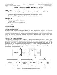
Tracks<br />
The tracks for JR come from a remote controlled bulldozer called “Excavator.”<br />
The rest of the toy was ripped apart, with the hope that other motors or gears may be<br />
used, but that was not possible. To provide enough strength to move the platform, the<br />
motors and gears used to drive the Excavator were gutted and two 48 oz. in. hacked<br />
servos were epoxied directly to the drive axle for each side (Figure 2)<br />
Platform<br />
Track Servos<br />
Figure 2: Drive Servos<br />
The electronics for JR are mounted on a platform that is attached above the tracks.<br />
This platform is a 9” by 10” piece of plexiglas, surrounded by 0.75” aluminum angle, for<br />
strength. Also mounted on this platform is a frame made of 0.5” aluminum angle, which<br />
supports the conveyor belt. Mounted to the front of the frame is an unhacked servo,<br />
which raises and lowers the conveyor belt, with the help of two springs, mounted to the<br />
back of the frame, to offset the weight of the conveyor belt.<br />
7
Conveyor Belt<br />
The most difficult aspect of JR was the conveyor belt. This would have to be<br />
strong enough to dig, but also light enough so the robot would be able to move at all.<br />
The frame of the conveyor belt is constructed of two 2” by 36” by 0.125” pieces of<br />
aluminum bar. Pieces of 0.25” all-thread and nuts are used to keep the spacing between<br />
the two bars at 4”. At the front and rear of the frame, bearings were epoxied to the<br />
aluminum for the axles. Bicycle sprockets were attached to the axles. Two lengths of<br />
bicycle chain were stretched across the sprockets, one on each side. Attached between<br />
the chains was a narrow length of shower curtain. A piece of plastic window molding<br />
was cut into 5” pieces. These pieces were stitched to the shower curtain every 9” to act<br />
as scoops.<br />
At about the middle of the conveyor belt lengthwise, on the right side of JR, a<br />
rectangular hole was cut in the aluminum to house the drive motor. Another sprocket<br />
was glued on the servo, to drive the chain. This assembly was mounted in a way so the<br />
sprocket would touch both the top and bottom section of chain, to provide maximum<br />
force, and reduce skipping of the chain. Also to reduce skipping, a chain<br />
tensioner/derailer had to be fashioned. It consisted of a piece of all-thread bent at a 90°<br />
angle twice that had a small sprocket attached to it. The all-thread was bolted to the<br />
aluminum frame of the conveyor belt. The sprocket was lined up with the chain and a<br />
spring was used to keep it tight.<br />
Since the conveyor belt was entirely too large to be lifted by the 100 oz. in. servo<br />
attached to it, two springs were added in the rear to offset the weight in the front. These<br />
springs were strong enough to keep the belt at almost a horizontal position at equilibrium,<br />
while not too tight for the servo to lower it to a digging position.<br />
Attached to the front of the conveyor belt are two pieces of plexiglas, one at each<br />
end, bent to 60° angles. The sonar and IR sensors are attached to these, to keep them as<br />
close to the front of the robot as possible. Since the conveyor belt is held at a horizontal<br />
position while in motion, these sensors ‘see’ straight forward.<br />
8
Actuation<br />
The actuation of JR is another major concern. Basic servos and DC motors would<br />
not be strong enough to move this robot, due to its weight. For the drive motors, two 48<br />
oz. in. servos were hacked to DC motors. These motors drew a stall current of 0.55 A<br />
each. They were attached directly to the motor driver on the ME11 board.<br />
To raise and lower the conveyor belt, a stronger servo was needed. Here, a 120<br />
oz. in. servo was used, connected to an output compare line of the 68HC11 board. To<br />
offset some of the weight of the conveyor belt and help the servo, two springs were<br />
attached to the back of the belt.<br />
Finally, the strongest actuator on the entire robot had to be the one to drive the<br />
conveyor belt. A 306 oz. in. hacked servo was used here. It was attached to a motor<br />
driver, made simply of a TIP transistor, connected to the Port D 3 pin. A sprocket is<br />
attached to this servo, which turns the chain for the conveyor belt.<br />
9
Sensors<br />
The sensors used on this robot platform are used for only two purposes:<br />
navigation and detecting metal. The sensors used for navigation are infrared (IR), sonar,<br />
and CDS cells. The IR and sonar are being used for object avoidance while the CDS<br />
cells are used to make the robot move towards some beacon. For detecting metal,<br />
obviously a metal detector will be used.<br />
Infrared (IR)<br />
The IR sensors on the robot are being used for object avoidance. A 40 kHz signal<br />
is sent to an IR led, this signal is bounced off of anything in front of the module, and then<br />
the signal is then observed by the Sharp can. The level of the output increases as the<br />
robot moves closer to any objects, as shown in Figure 3.<br />
Ir Reading(0-255)<br />
130<br />
120<br />
110<br />
100<br />
90<br />
80<br />
Figure 3<br />
3.0 5.0 7.0 9.0 11.0 13.0 16.0 20.0 24.0<br />
Distance(in)<br />
These readings were taken in a dark room, with the signal being reflected off of a<br />
white, glossy textbook. Because of the IR emitted by the sun, it is not feasible to use IR<br />
outside for any great distances. However, for uses inside, it appears to be a very reliable<br />
system. Because of this, IR will only be used as a last ditch measure to avoid obstacles.<br />
10
Sonar<br />
As with the IR system, the sonar on this robot is being used for collision<br />
avoidance. However, the sonar is using time of flight, instead of strength of signal to<br />
measure distance. The software the microprocessor uses sends out a 1 μsec pulse to an<br />
emitter. The software then polls a receiver until it receives the pulse back, while<br />
incrementing a counter. This counter is used to interpret the distance from the object,<br />
using the speed of sound and how long it takes to go through the loop. The data observed<br />
in the sonar test is in Figure 4.<br />
Sonar(counter)<br />
10.0<br />
9.0<br />
8.0<br />
7.0<br />
6.0<br />
5.0<br />
4.0<br />
3.0<br />
2.0<br />
1.0<br />
0.0<br />
Figure 4<br />
0.0 0.5 1.0 1.5 2.0 2.5 3.0 3.5 4.0 4.5 5.0<br />
Distance(ft)<br />
The data shown ignores noise that was seen. There were many readings of zero<br />
and 1000. These readings will have to be ignored, and any other readings taken will need<br />
to be averaged to have any data that is usable. Also, this data was taken using Interactive<br />
C. By the time the final project was done, JR was programmed with ICC11. The values<br />
of the counter were different, but the same accuracy of the data was observed. The valid<br />
values of the counter are now between 5 and 70. Because of noise, any readings below 5<br />
and above 100 are ignored.<br />
11
The circuit used for the Sonar was borrowed from William O’Connor’s report for<br />
Ranos. The only difference is the orientation of the transformer for the emitter is<br />
reversed. (Figure 5)<br />
Figure 5<br />
CDS Cells<br />
The receiver circuit is exactly the same one used in the Ranos project. (Figure 6)<br />
Figure 6<br />
CDS cells are used to detect the amount of light observed. As they detect more<br />
light, their resistance decreases. For testing, a 60-Watt bulb was placed at varying<br />
distances from the cell in a dark room. The data is in Figure 7.<br />
12
CDS (Analog In)<br />
250<br />
200<br />
150<br />
100<br />
50<br />
0<br />
Figure 7<br />
While this data was taken at a relatively close distance, CDS was intended to be<br />
used at a long distance. To do this, the resistor that is in series with the detector was<br />
increased. This gave a wider range of values and allowed the cell to detect weaker<br />
sources of light. Because the demonstration of JR was done during daylight hours, the<br />
CDS cells were not implemented.<br />
<strong>Metal</strong> <strong>Detector</strong><br />
3 9 15 21 27 33 39 45<br />
Distance (in)<br />
The metal detector is the most important sensor in this design. The values sent<br />
into the microprocessor were between 1 and 2 volts, for no reading, and full scale,<br />
respectively. These values translate to digital values of 50 to 100.<br />
For all tests, the metal detector was giving very accurate and repeatable readings.<br />
However, the night before demo day, the metal detector fried. While the problem was<br />
researched, no reason was found. Because of the malfunction, the metal detector was<br />
bypassed with a switch.<br />
13
Behaviors<br />
Obstacle Avoidance<br />
JR uses sonar and IR for obstacle avoidance. When one of the transducers<br />
receives a reading within the acceptable range, it reverses the opposite motor for a set<br />
amount of time. This turns the robot away from an object on one side, and backs it up<br />
away from an object in front of it.<br />
Sonar is the main system for obstacle avoidance. However, if there is a<br />
malfunction with sonar, IR may see an obstacle before JR runs into it. IR is strictly a<br />
backup, though.<br />
Beacon Following<br />
As JR moves, the CDS cells are scanning for the amount of light visible. If there<br />
is more light visible by the left cell, JR lists to the left until the light values are equal.<br />
The same is true for the right. This behavior allows JR to move toward a beacon placed<br />
many yards away from the robot.<br />
<strong>Metal</strong> Detecting<br />
As JR moves around, the microprocessor is continuously polling the metal<br />
detector. If a high reading is ever found, JR switches to digging mode. Otherwise, JR<br />
continues obstacle avoidance and beacon following.<br />
Digging<br />
The most difficult behavior for JR is digging. Once an object is detected, JR<br />
moves back for a set amount of time. Once there, the conveyor belt starts turning and is<br />
lowered into position to dig up dirt. The robot then moves forward for another amount of<br />
time. Then the belt is raised and stopped and JR goes back to normal operation.<br />
14
Experimental Layout and Results<br />
Creating JR was done in three basic parts. Sensors, programming, and<br />
mechanical designing was done separately and put together at the end. This was a<br />
mistake. Initially, the sonar system was tested and working well, but as soon as it was<br />
installed on the platform, many problems arose. First, when the transmitter sends the<br />
signal, it is still ringing in the aluminum by the time the receiver is being polled. This<br />
gives false readings, and a delay had to be put in the code before it detected a received<br />
signal. This is why this sonar configuration is not adequate for close readings.<br />
Another problem with the sonar system is the very small signal sent to the sonar<br />
receiver circuit by the receiver. The receiver was not getting any signals because of the<br />
length of the conveyor belt. The circuit had to be moved into the frame of the belt, and<br />
covered in electrical tape to protect it.<br />
The last major problem was the metal detector. Testing it by itself gave great<br />
results, but as soon as it was placed below the conveyor belt, it detected the aluminum in<br />
it. The normal state of the belt had to be raised to move it away from the metal detector.<br />
Initially, JR was going to be programmed in IC. However, there are problems<br />
with using two motors and a servo in IC. For that reason, ICC11 was used. In version 5,<br />
however, there are problems with the motor command. There is speed control, but the<br />
motors cannot be reversed. The motor routine given is to be used with the Talrik<br />
platform, but does not work on the ME11 board. To fix this, Darren Kelley wrote a<br />
subroutine that sets a PortD bit high or low, and controls the motor direction. Now to use<br />
ICC11 v5 with the ME11 board, the programmer can paste this subroutine at the end of<br />
the code and this will fix any problems. This subroutine is located at the end of JR’s<br />
code.<br />
15
Conclusions<br />
While the metal detector malfunctioned at the last minute, and the CDS cells were<br />
not implemented on Demo day, the robot was successful. The greatest success of JR is<br />
the conveyor belt. More hours were spent on perfecting the operation of the belt than any<br />
other single part of the platform. All through design, the belt would slip off of the gears.<br />
Finally after mounting the sprockets much more accurately, the belt stayed on. Then<br />
building the chain tensioner/derailer kept the chain on the drive gears well.<br />
The largest problem with JR is also the conveyor belt. While it functions well, it<br />
is not currently strong enough to actually dig. To make it dig, the scoops would have to<br />
be attached in a firmer manner.<br />
Future work on this robot would include making it much more robust. The first<br />
part of work would be determining what made the metal detector malfunction and fix the<br />
problem. The part would be making the scoops firmer so they would actually dig.<br />
Overall, JR performed well. While some of the previous problems and future<br />
work would have enhanced its performance, there was a lot accomplished this semester.<br />
16
Documentation<br />
Many people inside and outside of IMDL helped with this project. Darren Kelley<br />
worked with me a lot to develop the sonar code used, as well as the fix for the motor<br />
problem with ICC11. Without the sewing help of Corrie Ross, the conveyor belt would<br />
not have had a belt in it for demo day. Brent Fox donated all the bicycle parts used in the<br />
construction of the conveyor belt (many sprockets, a derailer the was torn apart, and the<br />
chains.) Finally, the following people helped out as the semester went along with ideas<br />
to fix various problems: Scott Jantz, Aamir Qaiyumi, Patrick O’Malley, Eric Anderson,<br />
Megan Grimm, and many others I’m sure I’m forgetting here.<br />
17
Vendors<br />
All parts not listed here were either obtained from the IMDL lab, common items from<br />
Radio Shack, or scrap pieces picked up from Ace Hardware.<br />
The servos were ordered from several different vendors. However, most vendors offered<br />
the same servos at similar prices. Also, prices would fluctuate in as small amount of time<br />
as a couple of weeks. For this reason, it is best to start pricing servos well before they are<br />
needed and keep an eye on the prices.<br />
Electronic Goldmine<br />
Sonar Transducers<br />
Part description: 40 kHz ultrasonic transducers, 15/16” diameter<br />
Part #: G2528<br />
Unit price: $1.50<br />
Website: http://www.goldmine-elec.com<br />
Maxim Integrated Products<br />
Sonar Filter (MAX266)<br />
Part description: switched-capacitor active filters<br />
Part #: MAX266ACPI<br />
Unit price: unknown<br />
Website: http://www.maxim-ic.com<br />
Radio Shack<br />
Part Description: audio output transformer, 1K ohm to 8 ohm<br />
Part #: 273-1380<br />
Unit price: $1.99<br />
Part Description: <strong>Metal</strong> detector<br />
Part #: 63-3005<br />
Unit price: $49.99<br />
18
Appendix A<br />
Sonar Test Code<br />
/* Justin Cobb ('borrowed' from Megan Grimm) */<br />
/* 3/21/99 */<br />
/* Sonar testing program */<br />
int counter;<br />
void main()<br />
{<br />
init_serial();<br />
counter=0;<br />
while(1)<br />
{<br />
counter=0;<br />
init_serial();<br />
msleep(1L);<br />
poke(0x7000,0x00);<br />
}<br />
while((analog(3)>200)&&(counter
Appendix B<br />
JR Main Program<br />
/************************Main Program*******<br />
* Justin Cobb<br />
* Revision (Who Knows)<br />
********************************************/<br />
/******** Includes ********/<br />
#include <br />
#include <br />
/******** Defines ********/<br />
#define Output_Latch *(unsigned char *)(0x7000)<br />
/******* Prototypes ******/<br />
void motor(int, int);<br />
void LeftSonar(void);<br />
void RightSonar(void);<br />
void TurnAway(void);<br />
/********** Variables ***********/<br />
long i, j;<br />
int IrRt_tmp, IrLft_tmp, IrRt, IrLft, RtSpd, LftSpd;<br />
int LeftThresh, RightThresh, counterlft, counterrt, SnrLvl;<br />
int Rt = 0;<br />
int Lft = 1;<br />
int Rt_IR = 0;<br />
int Lft_IR = 4;<br />
int SonarLft = 0x08;<br />
int SonarRt = 0x01;<br />
int Sonar = 7;<br />
int MDetect = 3;<br />
int <strong>Metal</strong>Thresh = 0x40;<br />
int belt = 0x04;<br />
int Servoval = 0;<br />
int ServoDrive = 2300;<br />
int ServoDig = 3600;<br />
int Clear = 0;<br />
/************* Main ****************/<br />
void main(void)<br />
{<br />
init_analog();<br />
init_motortk();<br />
init_clocktk();<br />
init_servos();<br />
init_serial();<br />
DDRD = 0xff;<br />
CLEAR_BIT(PORTD, belt);<br />
for(i = 3350; i > 1750; i--)<br />
servo(0, i);<br />
motor(0, 0);<br />
motor(1, 0);<br />
Output_Latch = 0x00;<br />
while(1)<br />
{<br />
LeftSonar();<br />
RightSonar();<br />
20
}<br />
}<br />
if ((RtSpd == -100) || (LftSpd == -100))<br />
TurnAway();<br />
motor(Rt, RtSpd);<br />
motor(Lft, LftSpd);<br />
if (analog(MDetect) > 240)<br />
{<br />
RtSpd = -100;<br />
LftSpd = -100;<br />
motor(Rt, RtSpd);<br />
motor(Lft, LftSpd);<br />
for(i = 0; i < 5000; i++)<br />
{<br />
for(j = 0; j < 1; j++);<br />
}<br />
motor(Rt, 0);<br />
motor(Lft, 0);<br />
SET_BIT(PORTD, belt);<br />
for(i = ServoDrive; i < ServoDig; i++)<br />
{<br />
servo(Servoval, i);<br />
for(j = 0; j < 5; j++);<br />
}<br />
motor(Rt, 25);<br />
motor(Lft, 25);<br />
for(i = 0; i < 5000; i++)<br />
{<br />
for(j = 0; j < 5; j++);<br />
}<br />
motor(Rt, 0);<br />
motor(Lft, 0);<br />
for(i = ServoDig; i > ServoDrive; i--)<br />
{<br />
servo(Servoval, i);<br />
for(j = 0; j < 5; j++);<br />
}<br />
CLEAR_BIT(PORTD, belt);<br />
}<br />
/************* End Main ****************/<br />
void LeftSonar(void)<br />
{<br />
counterlft = 0;<br />
SnrLvl = 255;<br />
Output_Latch = SonarLft;<br />
for(i = 0; i < 100; i++);<br />
Output_Latch = Clear;<br />
}<br />
while((SnrLvl > 125) && (counterlft < 300))<br />
{ SnrLvl = analog(7);<br />
counterlft++;<br />
}<br />
if ((counterlft < 100) && (counterlft > 5))<br />
LftSpd = -100;<br />
else LftSpd = 100;<br />
void RightSonar(void)<br />
{<br />
counterrt = 0;<br />
SnrLvl = 255;<br />
Output_Latch = SonarRt;<br />
for(i = 0; i < 100; i++);<br />
Output_Latch = Clear;<br />
21
}<br />
while((SnrLvl > 125) && (counterrt < 300))<br />
{ SnrLvl = analog(7);<br />
counterrt++;<br />
}<br />
if ((counterrt < 100) && (counterrt > 5))<br />
RtSpd = -100;<br />
else RtSpd = 100;<br />
void TurnAway(void)<br />
{<br />
}<br />
motor(Rt, RtSpd);<br />
motor(Lft, LftSpd);<br />
for(i = 0; i < 5000; i++);<br />
void motor(int index, int percent)<br />
/**************************** motor *****************************<br />
* Description<br />
* Sets the speed and direction for the motors.<br />
*<br />
*<br />
*<br />
*Usage: to controls motor direction<br />
************************************************************************/<br />
{<br />
if (index == 0)<br />
{ /* Set the Direction for motor0*/<br />
if ( percent < 0)<br />
{ SET_BIT(PORTD, 0x20); /* SET PD5 to high */<br />
printf("you are in the motor function index 0\n");<br />
motortk(index, percent); /* Call motor command*/<br />
}<br />
else<br />
{ CLEAR_BIT(PORTD, 0x20); /* Set PD5 to low */<br />
motortk(index, percent); /* Call motor command*/<br />
}<br />
}<br />
else if (index == 1)<br />
{ /* Set the direction of the motor1 */<br />
printf("you are in the motor function index 1\n");<br />
if ( percent < 0)<br />
{ SET_BIT(PORTD, 0x10); /* Set PD4 to high*/<br />
motortk(index, percent); /* Call motor command*/<br />
}<br />
else<br />
{ CLEAR_BIT(PORTD, 0x10); /* Set PD4 to low*/<br />
motortk(index, percent); /* Call motor command*/<br />
}<br />
}<br />
}<br />
/**************************** motor **** *****************************/<br />
22