Lab 3: Theorems and the Wheatstone Bridge - University of Florida
Lab 3: Theorems and the Wheatstone Bridge - University of Florida
Lab 3: Theorems and the Wheatstone Bridge - University of Florida

You also want an ePaper? Increase the reach of your titles
YUMPU automatically turns print PDFs into web optimized ePapers that Google loves.
<strong>University</strong> <strong>of</strong> <strong>Florida</strong> EEL 3111 — Summer 2010 Drs. E. M. Schwartz & R. Srivastava<br />
Department <strong>of</strong> Electrical & Computer Engineering Michael D. Grounds, TA<br />
Page 1/5 Revision 1 7-Jun-10<br />
<strong>Lab</strong> 3: <strong>Theorems</strong> <strong>and</strong> <strong>the</strong> <strong>Wheatstone</strong> <strong>Bridge</strong><br />
OBJECTIVES<br />
To reinforce <strong>and</strong> verify <strong>the</strong> concepts behind <strong>the</strong> Superposition, Thévenin’s, <strong>and</strong> Norton’s<br />
<strong>Theorems</strong><br />
To introduce <strong>and</strong> underst<strong>and</strong> <strong>the</strong> concepts behind maximum power transfer<br />
To underst<strong>and</strong> <strong>the</strong> design <strong>and</strong> use <strong>of</strong> a <strong>Wheatstone</strong> bridge circuit<br />
MATERIALS<br />
The lab assignment (this document).<br />
Your lab parts.<br />
Pre-lab questions including Multisim.<br />
Graph paper.<br />
INTRODUCTION<br />
The Superposition Theorem<br />
A statement <strong>of</strong> <strong>the</strong> superposition <strong>the</strong>orem is that <strong>the</strong> total effect <strong>of</strong> independent sources in a linear circuit<br />
is <strong>the</strong> algebraic sum <strong>of</strong> <strong>the</strong> effects <strong>of</strong> <strong>the</strong> independent sources considered separately. In <strong>the</strong> application<br />
<strong>of</strong> this <strong>the</strong>orem, <strong>the</strong> effect <strong>of</strong> only one independent source is considered at a time. All o<strong>the</strong>r independent<br />
sources are eliminated by replacing <strong>the</strong>m with short circuits if <strong>the</strong>y are voltage sources <strong>and</strong> with open<br />
circuits if <strong>the</strong>y are current sources.<br />
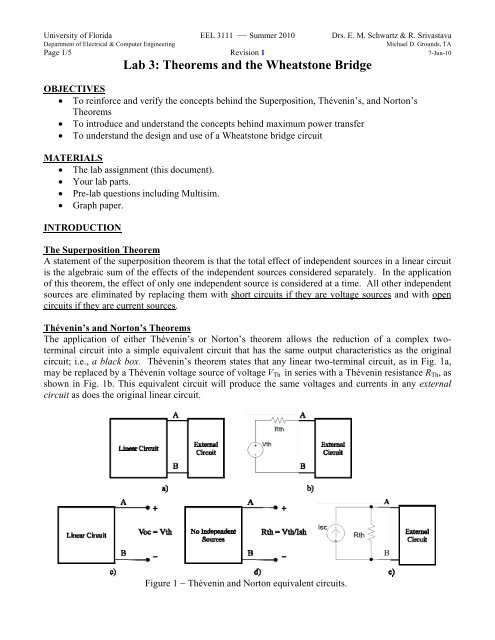
Thévenin’s <strong>and</strong> Norton’s <strong>Theorems</strong><br />
The application <strong>of</strong> ei<strong>the</strong>r Thévenin’s or Norton’s <strong>the</strong>orem allows <strong>the</strong> reduction <strong>of</strong> a complex twoterminal<br />
circuit into a simple equivalent circuit that has <strong>the</strong> same output characteristics as <strong>the</strong> original<br />
circuit; i.e., a black box. Thévenin’s <strong>the</strong>orem states that any linear two-terminal circuit, as in Fig. 1a,<br />
may be replaced by a Thévenin voltage source <strong>of</strong> voltage VTh in series with a Thévenin resistance RTh, as<br />
shown in Fig. 1b. This equivalent circuit will produce <strong>the</strong> same voltages <strong>and</strong> currents in any external<br />
circuit as does <strong>the</strong> original linear circuit.<br />
Figure 1 Thévenin <strong>and</strong> Norton equivalent circuits.
<strong>University</strong> <strong>of</strong> <strong>Florida</strong> EEL 3111 — Summer 2010 Drs. E. M. Schwartz & R. Srivastava<br />
Department <strong>of</strong> Electrical & Computer Engineering Michael D. Grounds, TA<br />
Page 2/5 Revision 1 7-Jun-10<br />
<strong>Lab</strong> 3: <strong>Theorems</strong> <strong>and</strong> <strong>the</strong> <strong>Wheatstone</strong> <strong>Bridge</strong><br />
The Thévenin voltage VTh is <strong>the</strong> open-circuit voltage across <strong>the</strong> two node terminals <strong>of</strong> <strong>the</strong> original<br />
circuit, as shown in Fig. 1c. The Thévenin resistance RTh is <strong>the</strong> resistance “looking” into <strong>the</strong> two<br />
terminals A <strong>and</strong> B, as shown in Fig. 1d, with all independent sources deactivated: all <strong>the</strong> voltage sources<br />
are replaced by short circuits, <strong>and</strong> current sources by open circuits.<br />
For Norton’s <strong>the</strong>orem, <strong>the</strong> equivalent circuit is a current source in parallel with a resistor <strong>of</strong> <strong>the</strong> same<br />
Thévenin resistance RTh, as shown in Fig. 1e. The current ISC <strong>of</strong> <strong>the</strong> current source is <strong>the</strong> current in a<br />
short circuit placed across terminals A <strong>and</strong> B, with a direction <strong>of</strong> A to B.<br />
Maximum Power Transfer<br />
In some circuits, maximum power transfer to a load resistor is desired. One example <strong>of</strong> such a circuit is<br />
in an audio system in which <strong>the</strong> load is <strong>the</strong> resistance <strong>of</strong> a speaker. It is desirable for <strong>the</strong> speaker to<br />
absorb <strong>the</strong> maximum power that <strong>the</strong> audio circuit can deliver.<br />
As shown in Fig. 2, <strong>the</strong> circuit delivering power to <strong>the</strong> load can, for analysis purposes, be replaced by its<br />
Thévenin equivalent. Then, as proved in almost any circuits textbook, <strong>the</strong> load resistor that will absorb<br />
maximum power has a resistance equal to <strong>the</strong> Thévenin resistance. Specifically, for maximum power<br />
transfer,<br />
RL = RTh ,<br />
as shown in Fig. 2.<br />
Combining <strong>the</strong> load resistance with <strong>the</strong> Thévenin resistance, <strong>the</strong> load current is<br />
I = VTH / (RTH + RTH) = VTH / 2RTH .<br />
Thus, <strong>the</strong> power absorbed by <strong>the</strong> load resistor is<br />
P = I 2 RL = [VTH / (RTH + RL)] 2 RL .<br />
The maximum power transferred to a matching load (RL = RTH) is <strong>the</strong>refore given by<br />
PMAX = VTH 2 / 4RTH .<br />
Figure 2 Maximum power transfer occurs when RL = RTh
<strong>University</strong> <strong>of</strong> <strong>Florida</strong> EEL 3111 — Summer 2010 Drs. E. M. Schwartz & R. Srivastava<br />
Department <strong>of</strong> Electrical & Computer Engineering Michael D. Grounds, TA<br />
Page 3/5 Revision 1 7-Jun-10<br />
<strong>Lab</strong> 3: <strong>Theorems</strong> <strong>and</strong> <strong>the</strong> <strong>Wheatstone</strong> <strong>Bridge</strong><br />
<strong>Wheatstone</strong> <strong>Bridge</strong> <strong>and</strong> Resistance Measurements<br />
In 1843, <strong>the</strong> English scientist Charles <strong>Wheatstone</strong> invented <strong>the</strong> bridge circuit bearing his name. It is<br />
widely used for rapid <strong>and</strong> precise resistance measurements. O<strong>the</strong>r similar bridges can be used to<br />
measure capacitance or inductance.<br />
Although a commercial <strong>Wheatstone</strong> bridge may contain precision resistors, switches, <strong>and</strong> potentiometers<br />
to protect <strong>the</strong> meter movement, <strong>and</strong> perhaps a variable voltage source, <strong>the</strong> simplified circuit <strong>of</strong> Fig. 3<br />
will be used here to illustrate <strong>the</strong> basic principles. The resistances Rn, Rm, <strong>and</strong> Rp are known, <strong>and</strong> <strong>the</strong><br />
resistance Rx is to be determined. The resistance Rp is variable. The meter between nodes b <strong>and</strong> c can be<br />
a sensitive ammeter or voltmeter.<br />
In <strong>the</strong> use <strong>of</strong> <strong>the</strong> bridge, <strong>the</strong> resistance <strong>of</strong> Rp is adjusted until <strong>the</strong> meter movement shows no deflection.<br />
Then Vd, <strong>the</strong> detector voltage, is zero, which means that nodes b <strong>and</strong> c must be at <strong>the</strong> same potential.<br />
Consequently, <strong>the</strong> voltage drop from a to b equals that from a to c. Also, <strong>the</strong> voltage drop from b to d<br />
equals that from c to d. Fur<strong>the</strong>r, since <strong>the</strong> meter current is zero, <strong>the</strong> current I1 flows through resistor Rn<br />
<strong>and</strong> also through resistor Rm. Similarly, <strong>the</strong> current I2 flows through resistors Rp <strong>and</strong> Rx. Since Vab = Vac,<br />
<strong>the</strong>n I1Rn = I2Rp. Also, since Vbd = Vcd, <strong>the</strong>n I1Rm = I2Rx. The division <strong>of</strong> equations yields:<br />
I2Rx / I2Rp = I1Rm / I1Rn ,<br />
which reduces to<br />
Figure 3 Simplified <strong>Wheatstone</strong> bridge circuit for measuring resistance.<br />
Rx = Rp ( Rm/Rn ) (bridge balance equation).<br />
This is <strong>the</strong> bridge balance equation. With <strong>the</strong> bridge balanced, this equation can be used to determine<br />
<strong>the</strong> resistance Rx to a precision that is nominally <strong>the</strong> same as <strong>the</strong> precision <strong>of</strong> <strong>the</strong> resistances Rm, Rn, <strong>and</strong><br />
Rp.<br />
During <strong>the</strong> preliminary adjustments, when <strong>the</strong> bridge may be far from a balanced condition, <strong>the</strong> meter<br />
movement must be protected by a variable series resistor <strong>the</strong> resistance <strong>of</strong> which is large compared with<br />
that <strong>of</strong> <strong>the</strong> meter. If, however, <strong>the</strong> voltage supply Vs is variable, <strong>the</strong> variable series resistor may not be
<strong>University</strong> <strong>of</strong> <strong>Florida</strong> EEL 3111 — Summer 2010 Drs. E. M. Schwartz & R. Srivastava<br />
Department <strong>of</strong> Electrical & Computer Engineering Michael D. Grounds, TA<br />
Page 4/5 Revision 1 7-Jun-10<br />
<strong>Lab</strong> 3: <strong>Theorems</strong> <strong>and</strong> <strong>the</strong> <strong>Wheatstone</strong> <strong>Bridge</strong><br />
needed. Then, <strong>the</strong> voltage Vs can be gradually increased from zero to some maximum voltage, with<br />
repetitive attempts to balance <strong>the</strong> bridge at intermediate values <strong>of</strong> voltage. This is an equally safe <strong>and</strong><br />
accurate method for balancing <strong>the</strong> bridge.<br />
PRE-LAB AND QUESTIONS<br />
1. Find <strong>the</strong> voltage Vo across 2.2-k resistor in <strong>the</strong> circuit shown in Fig. 4 analytically.<br />
2. Use Multisim to construct <strong>the</strong> circuit <strong>of</strong> Fig. 4.<br />
a. Measure Vo in your simulation <strong>and</strong> take a screenshot <strong>of</strong> this measurement.<br />
b. Replace <strong>the</strong> 9V source with a short-circuit <strong>and</strong> measure <strong>the</strong> portion <strong>of</strong> Vo contributed by <strong>the</strong> 15V<br />
source. Take a screenshot <strong>of</strong> this measurement.<br />
c. Replace <strong>the</strong> 15V source with a short-circuit <strong>and</strong> measure <strong>the</strong> portion <strong>of</strong> VO contributed by <strong>the</strong> 9V<br />
source. Take a screenshot <strong>of</strong> this measurement.<br />
d. Find VO in <strong>the</strong> original circuit by adding <strong>the</strong> voltages calculated in parts b <strong>and</strong> c. Compare this<br />
answer with <strong>the</strong> one you got in part a. You have just demonstrated superposition!<br />
e. For <strong>the</strong> circuit in Fig. 4, replace R4 with an open circuit <strong>and</strong> measure <strong>the</strong> resulting voltage at <strong>the</strong><br />
open circuit. Take a screenshot <strong>of</strong> this measurement.<br />
f. For <strong>the</strong> circuit in Fig. 4, replace R4 with a short circuit <strong>and</strong> measure <strong>the</strong> resulting current in that<br />
short. (In <strong>the</strong> actual circuit, you could use your DMM as your short circuit.). Take a screenshot<br />
<strong>of</strong> this measurement.<br />
g. Find <strong>the</strong> Thévenin's <strong>and</strong> Norton's<br />
equivalent circuits as seen by <strong>the</strong> 2.2 k<br />
load resistance. Build <strong>the</strong> Thévenin’s<br />
equivalent circuit in Multisim using <strong>the</strong><br />
2.2 kresistor as your load.. (Hint: See<br />
<strong>the</strong> schematic in Fig. 1b.) Measure <strong>the</strong><br />
current through <strong>the</strong> load resistor <strong>and</strong> take<br />
a screenshot <strong>of</strong> this value. How does this<br />
compare to <strong>the</strong> value you found in step f?<br />
h. Plot <strong>the</strong> power absorbed by <strong>the</strong> load as a<br />
function <strong>of</strong> <strong>the</strong> load resistance RL for VTH<br />
<strong>and</strong> RTH by varying RL from 1 k to 10<br />
k. Determine, from <strong>the</strong> graph, <strong>the</strong><br />
maximum power <strong>and</strong> <strong>the</strong> corresponding<br />
value <strong>of</strong> RL. For what resistance is <strong>the</strong> maximum power absorbed?<br />
Figure 4 Example circuit for pre-lab analysis.<br />
3. Repeat part 2 b-g analytically, i.e., with equations, <strong>and</strong> report any significant difference with what<br />
was found in part 2.<br />
LAB PROCEDURE AND QUESTIONS<br />
The Superposition Theorem<br />
1. Build <strong>the</strong> circuit <strong>of</strong> Fig. 4 <strong>and</strong> carry out steps 1b, 1c, <strong>and</strong> 1d <strong>of</strong> <strong>the</strong> pre-lab assignment by measuring<br />
<strong>the</strong> individual voltage contributions.<br />
CAUTION: Replace <strong>the</strong> voltage sources with short circuits. Do not place a short circuit across a<br />
voltage source because <strong>the</strong> resulting large current will destroy <strong>the</strong> voltage source.
<strong>University</strong> <strong>of</strong> <strong>Florida</strong> EEL 3111 — Summer 2010 Drs. E. M. Schwartz & R. Srivastava<br />
Department <strong>of</strong> Electrical & Computer Engineering Michael D. Grounds, TA<br />
Page 5/5 Revision 1 7-Jun-10<br />
<strong>Lab</strong> 3: <strong>Theorems</strong> <strong>and</strong> <strong>the</strong> <strong>Wheatstone</strong> <strong>Bridge</strong><br />
2. Determine <strong>the</strong> voltage Vo across <strong>the</strong> 2.2-k resistor by algebraically adding <strong>the</strong>se two measured<br />
voltages. Compare <strong>the</strong> result with <strong>the</strong> calculated value <strong>and</strong> also with <strong>the</strong> measured value <strong>of</strong> VO with<br />
both sources in <strong>the</strong> circuit.<br />
Thévenin’s <strong>and</strong> Norton’s <strong>Theorems</strong><br />
1. Construct <strong>the</strong> circuit <strong>of</strong> Fig. 4. The 2.2-k resistor will be considered to be <strong>the</strong> load.<br />
2. Using <strong>the</strong> DMM (digital multimeter) ammeter, measure <strong>the</strong> current flowing through <strong>the</strong> 2.2-k<br />
resistor.<br />
3. Remove <strong>the</strong> 2.2-k resistor <strong>and</strong> use <strong>the</strong> DMM voltmeter to measure <strong>the</strong> Thévenin voltage.<br />
4. Remove <strong>the</strong> 2.2-k resistor <strong>and</strong> use <strong>the</strong> DMM ammeter to measure <strong>the</strong> short-circuit current ISC.<br />
Find RTh again, but do so by using RTh = VTh/ISC. Does this value agree with <strong>the</strong> calculated value?<br />
5. Adjust <strong>the</strong> power supply to VTh <strong>and</strong> a potentiometer or decade resistance box to RTh, <strong>and</strong> connect<br />
<strong>the</strong>m in series with <strong>the</strong> 2.2-k resistor. Using <strong>the</strong> DMM ammeter, measure <strong>the</strong> current through <strong>the</strong><br />
2.2-kresistor. Does this value agree with <strong>the</strong> value from step 2?<br />
Maximum Power Transfer<br />
1. Build <strong>the</strong> Thévenin equivalent <strong>of</strong> <strong>the</strong> circuit <strong>of</strong> Fig. 4.<br />
2. Using a number <strong>of</strong> load resistances, with one <strong>of</strong> <strong>the</strong> values near RTh, find <strong>the</strong> power absorbed by each<br />
resistor by using two out <strong>of</strong> three measurements <strong>of</strong> load voltage, load current, <strong>and</strong> load resistance.<br />
Have three values <strong>of</strong> resistances greater than RTh, <strong>and</strong> three less. Make sure to spread out resistance<br />
values.<br />
3. Using <strong>the</strong> values obtained in Step 2, make a plot <strong>of</strong> power absorbed versus load resistance. Does <strong>the</strong><br />
plot peak at RTh? Is <strong>the</strong> plot symmetrical about <strong>the</strong> peak value? Do you expect it to be? Explain.<br />
<strong>Wheatstone</strong> <strong>Bridge</strong> <strong>and</strong> Resistance Measurements<br />
Construct a <strong>Wheatstone</strong> bridge circuit as shown in Fig. 3. Use <strong>the</strong> digital multimeter (DMM) for<br />
measuring dc current <strong>and</strong> voltage. Use a variable dc power supply for VS. Use st<strong>and</strong>ard carbon resistors<br />
for resistors Rm <strong>and</strong> Rn, <strong>and</strong> accurately measure <strong>the</strong>ir resistances with an ohmmeter (DMM) before<br />
assembling <strong>the</strong> bridge. The individual resistance values <strong>of</strong> Rm <strong>and</strong> Rn are not critical, but, as can be<br />
shown by a network sensitivity analysis, <strong>the</strong> ratio Rm/Rn should be between 0.4 <strong>and</strong> 6.0 for good results.<br />
Use a precision decade resistor for Rp. Of course, <strong>the</strong> resistor Rx is <strong>the</strong> resistor <strong>of</strong> initially unknown<br />
resistance.<br />
In using <strong>the</strong> bridge to determine Rx, start out with Vs at zero, <strong>and</strong> gradually increase it while<br />
simultaneously balancing <strong>the</strong> bridge by adjusting Rp. Make certain that <strong>the</strong> meter (DMM) is connected<br />
across <strong>the</strong> bridge (b to c). Then, adjust <strong>the</strong> variable resistor Rp to obtain zero volts. When balance is<br />
obtained for a sizable Vs, determine <strong>the</strong> resistance Rx from <strong>the</strong> bridge balance equation.<br />
Specifically,<br />
1. Use <strong>the</strong> bridge to measure <strong>the</strong> resistances <strong>of</strong> at least two miscellaneous resistors. Then, measure <strong>the</strong><br />
resistances with a DMM <strong>and</strong> compare.<br />
2. Determine <strong>the</strong> percentage variation <strong>of</strong> <strong>the</strong> measured value from <strong>the</strong> nominal resistance <strong>of</strong> each<br />
resistor. Comment on any variations <strong>of</strong> <strong>the</strong> results.