Design and Implementation of a GPS-Based Navigation System for ...
Design and Implementation of a GPS-Based Navigation System for ...
Design and Implementation of a GPS-Based Navigation System for ...

You also want an ePaper? Increase the reach of your titles
YUMPU automatically turns print PDFs into web optimized ePapers that Google loves.
DESIGN AND IMPLEMENTATION OF A <strong>GPS</strong>-BASED<br />
NAVIGATION SYSTEM FOR MICRO AIR VEHICLES<br />
Scott Kanowitz Michael Nechyba A. Antonio Arroyo<br />
skano@mil.ufl.edu nechyba@mil.ufl.edu arroyo@mil.ufl.edu<br />
Abstract<br />
Micro Air Vehicles (MAVs) are becoming vastly popular<br />
in the areas <strong>of</strong> surveillance <strong>and</strong> reconnisance <strong>for</strong> military<br />
<strong>and</strong> civilian use, however, their instability due to their<br />
small size renders them useful to only a h<strong>and</strong>ful <strong>of</strong> pilots.<br />
We propose implementing a <strong>GPS</strong>-based navigation system<br />
<strong>for</strong> use in autonomous flight <strong>of</strong> micro air vehicles. Previous<br />
ef<strong>for</strong>ts in this area have produced a vision-based horizon<br />
tracking algorithm capable <strong>of</strong> sustained level flight with<br />
user input. Our goal is to improve on this flight system using<br />
in<strong>for</strong>mation from a <strong>GPS</strong> receiver. In this paper we first<br />
introduce MAVs <strong>and</strong> the current vision-based navigation<br />
system. We next discuss the integration <strong>of</strong> the <strong>GPS</strong> navigation<br />
system by describing the design <strong>of</strong> the hardware system<br />
<strong>and</strong> s<strong>of</strong>tware algorithms <strong>for</strong> navigation <strong>and</strong> control.<br />
The <strong>GPS</strong> <strong>and</strong> vision-based navigation system has been successfully<br />
built <strong>and</strong> integrated, <strong>and</strong> is currently in the test<br />
phase <strong>of</strong> development.<br />
1. Introduction<br />
MAVs hold a great potential <strong>for</strong> use in the surveillance<br />
field. Equipped with small video cameras <strong>and</strong> transmitters,<br />
they can be used in areas too remote or dangerous <strong>for</strong> a human<br />
counterpart. Their small scale <strong>and</strong> low noise enables<br />
them to blend in with the sky <strong>and</strong> surroundings, rendering<br />
them unnoticeable. Even at low altitudes, their strong resemblance<br />
to insects <strong>and</strong> birds enables MAVs to operate<br />
unnoticed. This trait lends itself well to unobtrusive wildlife<br />
surveillance as well as a variety <strong>of</strong> military applications.<br />
The small size requirements <strong>of</strong> MAVs generate a variety<br />
<strong>of</strong> challenges in development not seen in their larger wing<br />
counterparts. These challenges fall into three broad categories:<br />
(1) aerodynamic efficiency, (2) increased wing loading,<br />
<strong>and</strong> (3) stability <strong>and</strong> control [2]. Solutions <strong>for</strong> the first<br />
<strong>and</strong> second challenges are currently being developed in the<br />
Micro Air Vehicle Laboratory at the University <strong>of</strong> Florida<br />
in the <strong>for</strong>m <strong>of</strong> innovative designs incorporating advanced<br />
materials [3]. In this paper we propose solving the third<br />
challenge <strong>of</strong> stability <strong>and</strong> control. We plan to implement a<br />
<strong>GPS</strong>-based navigation system into the existing visionbased<br />
navigation system to solve this challenge. The result-<br />
Machine Intelligence Laboratory<br />
Department <strong>of</strong> Electrical <strong>and</strong> Computer Engineering<br />
University <strong>of</strong> Florida, Gainesville, FL 32611-6200<br />
1<br />
ing flight control system will be capable <strong>of</strong> achieving fully<br />
autonomous flight, removing the human component from<br />
the control loop.<br />
The current <strong>GPS</strong> constellation which began operation in<br />
the early 1990’s allows <strong>for</strong> accurate l<strong>and</strong> based navigation<br />
with meter accuracy [1]. This system is widely becoming<br />
the st<strong>and</strong>ard <strong>for</strong> l<strong>and</strong> <strong>and</strong> air based navigation [9]. Within<br />
the United States, <strong>GPS</strong> has been approved as an IFR supplemental<br />
navigation system <strong>for</strong> domestic en route phases<br />
<strong>of</strong> flight, <strong>and</strong> as a primary means <strong>for</strong> oceanic navigation.<br />
[5].<br />
Presently, <strong>GPS</strong> is being added to the primary computer<br />
systems <strong>of</strong> large aircraft, increasing their navigation abilities.<br />
We feel <strong>GPS</strong> can also greatly alter the usability <strong>of</strong><br />
MAVs. The lack <strong>of</strong> stability <strong>and</strong> control inherent in MAVs<br />
renders them useful to only a h<strong>and</strong>ful <strong>of</strong> skilled pilots. With<br />
the proper navigation system the MAVs can be telecontrolled<br />
by a computer, eliminating the major stability challenges<br />
<strong>of</strong> flight, allowing any pilot to focus simply on<br />
altitude <strong>and</strong> direction. With a <strong>GPS</strong>-based navigation system<br />
the pilot can be further removed from the control loop.<br />
This system could fully control the flight <strong>of</strong> the aircraft allowing<br />
any person to operate the MAVs by simply programming<br />
a flight path.<br />
2. Overview <strong>of</strong> <strong>System</strong><br />
In developing MAVs we look to nature <strong>for</strong> the biological<br />
MAV counterpart, the bird. Most large winged aircraft<br />
are designed with rigid fixed wings to avoid catastrophic<br />
failures due to structural dynamics. Birds on the other h<strong>and</strong><br />
do not have rigid wings, <strong>and</strong> instead exhibit a great deal <strong>of</strong><br />
flexibility in their wings. The design <strong>of</strong> MAVs makes use<br />
<strong>of</strong> this flexible wing design to produce a passive mechanism<br />
called adaptive washout to suppress wind gusts’ effects<br />
on their stability. To implement this flexible wing<br />
concept, we make use <strong>of</strong> carbon fiber construction techniques<br />
to produce lightweight durable aircrafts.<br />
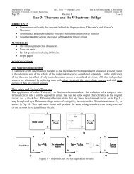
The planes developed <strong>for</strong> use in this research have wingspans<br />
from 24in to 5in. For initial tests a 24in MAV, shown<br />
in Figure 1, will be used since it has the highest payload capacity.<br />
The 24in plane is capable <strong>of</strong> carrying 150g in addition<br />
to its primary flight systems including servos, a motor,<br />
receiver, <strong>and</strong> batteries. Using a st<strong>and</strong>ard configuration, the
Fig. 1: Example MAV with 24in wingspan<br />
MAV is capable <strong>of</strong> sustained flight <strong>for</strong> up to 45min. This<br />
flight time is essential <strong>for</strong> close-range surveillance missions.<br />
The vision-based system takes advantage <strong>of</strong> the surveillance<br />
capabilities <strong>of</strong> MAVs. With a color camera <strong>and</strong> transmitter<br />
already included in the payload, the system does not<br />
rely on any additional payload to control the MAV. All the<br />
vision-based control work is done <strong>of</strong>f-board using a base<br />
station computer on the ground.<br />
The vision-based system derives its control using a direct<br />
measurement <strong>of</strong> the aircraft’s orientation with respect<br />
to the ground. The two degrees <strong>of</strong> freedom critical <strong>for</strong> stability<br />
in this measurement are the bank angle ( Φ)<br />
<strong>and</strong> the<br />
pitch angle ( Θ)<br />
. These two angles are determined directly<br />
from the horizon estimate <strong>of</strong> an image from a <strong>for</strong>ward facing<br />
camera on the aircraft. The bank angle is determined as<br />
the inverse tangent <strong>of</strong> the slope <strong>of</strong> the horizon line. The<br />
pitch angle is estimated to be closely proportional to the<br />
percentage <strong>of</strong> the image above or below the line.<br />
The horizon estimation algorithm begins with a course<br />
search <strong>of</strong> the image, fitting horizon estimates based on previously<br />
defined search parameters. The various sky <strong>and</strong><br />
ground regions resulting from this search are modeled as a<br />
Gaussian distribution in RGB space. Using the Gaussian<br />
model, the mean <strong>and</strong> covariance matrices <strong>of</strong> the two distributions<br />
are calculated <strong>and</strong> used in the cost function equation<br />
below<br />
F<br />
=<br />
Σ G<br />
+ ΣS +<br />
( λG1 + λG2 + λG3 ) 2 +<br />
( λS1 + λS2 + λS3 ) 2<br />
where ΣG denotes the covariance matrix <strong>for</strong> ground pixels,<br />
<strong>and</strong> ΣS denotes the covariance matrix <strong>for</strong> sky pixels. This<br />
cost function is used <strong>for</strong> computing the line with the highest<br />
likelihood <strong>of</strong> being the best-fit horizon [2].<br />
– 1<br />
(1)<br />
2<br />
3. Light-Weight <strong>GPS</strong> <strong>Navigation</strong> <strong>System</strong><br />
The integration <strong>of</strong> <strong>GPS</strong> navigation into the MAV control<br />
system consists <strong>of</strong> developing hardware <strong>and</strong> s<strong>of</strong>tware<br />
layers. When designing the hardware system we must consider<br />
the payload requirements <strong>of</strong> the MAV. This requirement<br />
is the main restriction as to what processing is done<br />
on the MAV.<br />
The on-board hardware enables the system to directly<br />
determine the <strong>GPS</strong> coordinates <strong>of</strong> the MAV using a <strong>GPS</strong><br />
receiver <strong>and</strong> antenna mounted on the plane. This system<br />
does not per<strong>for</strong>m any navigation processing <strong>and</strong> is only<br />
used to gather data. The system is responsible <strong>for</strong> collecting<br />
<strong>GPS</strong> data <strong>and</strong> transmitting it to the base station. The base<br />
station hardware is responsible <strong>for</strong> receiving the <strong>GPS</strong> data<br />
transmissions, <strong>and</strong> making them available <strong>for</strong> to the computer.<br />
3.1 Hardware Description<br />
To meet the small payload requirements <strong>of</strong> the MAV we<br />
searched <strong>for</strong> a small lightweight <strong>GPS</strong> receiver with st<strong>and</strong>ard<br />
functionality <strong>and</strong> limited user dependence. To satisfy<br />
these requirements, we used the Royaltek REB-2000 <strong>GPS</strong><br />
receiver. This unit is an 11-channel <strong>GPS</strong> receiver, transmitting<br />
NMEA update messages at 1HZ through a local serial<br />
port. The unit operates on 3.3V at less than 170mA <strong>and</strong><br />
weighs 8.6g. The weight <strong>of</strong> this receiver falls well within<br />
the payload requirements <strong>of</strong> the MAV.<br />
The documented error <strong>of</strong> the <strong>GPS</strong> receiver is in the<br />
range <strong>of</strong> 15m. The typical observed drift is around 7m to<br />
10m. These error measurements might seem too large <strong>for</strong><br />
raw navigation purposes, however, they are within control<br />
limits. The MAV must maintain considerable speed to stay<br />
airborne <strong>for</strong> proper operation. The average speed during<br />
test flights is around 40mph to 50mph. This amounts to<br />
around 20m <strong>of</strong> ground coverage per second. With <strong>GPS</strong> data<br />
updating at 1Hz, the drift due to error becomes tolerable<br />
since the MAV will always be outside the range <strong>of</strong> error by<br />
the time the next data set arrives. While this is not precise<br />
navigation, it is sufficient <strong>for</strong> following a general flight<br />
path based on waypoints.<br />
An equally small <strong>GPS</strong> antenna was needed to interface<br />
with the <strong>GPS</strong> receiver. When shrinking the size <strong>of</strong> a passive<br />
<strong>GPS</strong> antenna, signal degradation becomes large, <strong>and</strong> it is<br />
difficult to produce usable satellite transmissions. We determined<br />
we would need an active antenna with a sizable<br />
gain that consumes minimal power. The <strong>GPS</strong> antenna that<br />
meets our requirements is the Tri-M Micro Skymaster. This<br />
antenna has a 24dB gain with a maximum <strong>of</strong> 12mA current<br />
consumption. For the purposes <strong>of</strong> this project the antenna<br />
cable was shortened from 3ft. to 14in to reduce extra payload.<br />
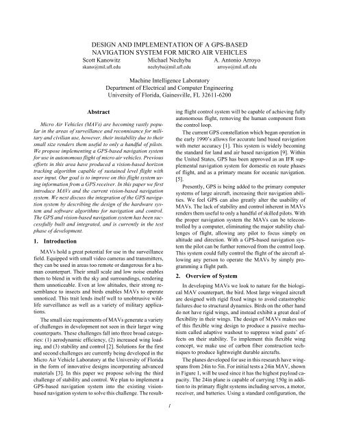
To satisfy the data transmission requirements, a system<br />
was designed using the TX1\RX1 FM serial data transmit-
Fig. 2: <strong>GPS</strong> receiver <strong>and</strong> data transmitter package<br />
ter/receiver pair designed by Radiometrix. These units operate<br />
on the 173.25MHz FM b<strong>and</strong> <strong>and</strong> can transmit at data<br />
rates up to 10 KBps. The overall range <strong>of</strong> the system can<br />
approach 10Km with the proper antennas <strong>and</strong> data rate. The<br />
TX1 <strong>and</strong> RX1 operate at 3.3V <strong>and</strong> have internal regulators.<br />
They consume 10mA on average. These properties <strong>of</strong> the<br />
TX1/RX1 make them suitable <strong>for</strong> use in MAV applications.<br />
3.2 S<strong>of</strong>tware Description<br />
The s<strong>of</strong>tware package <strong>for</strong> the <strong>GPS</strong>-based navigation<br />
system consists <strong>of</strong> three main control structures: (1) data input<br />
<strong>and</strong> extraction, (2) control system, <strong>and</strong> (3) vision system<br />
interface. These systems interact to gather data from<br />
the <strong>GPS</strong> receiver on the MAV, determine proper flight control<br />
changes to achieve the desired mission goals <strong>and</strong> interface<br />
with the current vision system. The s<strong>of</strong>tware is based<br />
on the flow diagram in Figure 3.<br />
The data input <strong>and</strong> extraction system is the first step in<br />
the program flow. The system is designed to directly interface<br />
with the <strong>GPS</strong> receiver <strong>and</strong> the base station data receiver.<br />
The <strong>GPS</strong> receiver is initialized to transmit NMEA <strong>GPS</strong><br />
sentences at 4800 Bps with a 1Hz update frequency. The<br />
data input <strong>and</strong> extraction s<strong>of</strong>tware reads these NMEA sentences<br />
from the RS-232 port <strong>and</strong> decodes them <strong>for</strong> use in<br />
Receive<br />
data<br />
Fig. 3: S<strong>of</strong>tware flow diagram<br />
Extract<br />
info<br />
Display<br />
engine<br />
Nav<br />
engine<br />
Flight<br />
controller<br />
3<br />
the other parts <strong>of</strong> the s<strong>of</strong>tware package. The system is extremely<br />
robust to account <strong>for</strong> invalid data due to signal degradation<br />
when flying at large distances from the base<br />
station.<br />
Included in the data input <strong>and</strong> extraction system is the<br />
data display console. This section provides the user with all<br />
the data transmitted from the <strong>GPS</strong> receiver as well as the<br />
current navigation data being used in the flight control system.<br />
It also enables the user to make changes to the flight<br />
path on the fly.<br />
The s<strong>of</strong>tware control system is the next step in the program<br />
flow. This system first takes the raw <strong>GPS</strong> data <strong>and</strong><br />
converts it into the proper units <strong>for</strong> use in the flight controller.<br />
It then uses the desired flight plan to determine the necessary<br />
navigation controls <strong>for</strong> achieving autonomous<br />
flight. The flight plan consists <strong>of</strong> a number <strong>of</strong> waypoints <strong>for</strong><br />
the MAV to traverse. The user designs a course based on<br />
latitude, longitude <strong>and</strong> altitude measurements at discrete<br />
points on the path. The system is designed around central<br />
PID controllers using two individual PID systems to control<br />
the direction or bearing <strong>and</strong> the altitude.<br />
The errors <strong>for</strong> the PID system are determined from the<br />
current <strong>GPS</strong> position data <strong>and</strong> the predetermined flight<br />
plan. The altitude is taken directly from the <strong>GPS</strong> GPGGA<br />
NMEA sentence. The position <strong>and</strong> course data are taken<br />
from the <strong>GPS</strong> GPRMC NMEA sentence. The bearing controller<br />
is updated using the error between the current bearing<br />
to the desired point <strong>and</strong> current course as shown in<br />
Figure 4. The altitude controller is updated using the error<br />
between the current <strong>and</strong> desired altitude.<br />
The bearing error is based on the current course <strong>and</strong> the<br />
bearing to the next requested waypoint in the predetermined<br />
flight path, <strong>and</strong> is calculated using the Great Circle<br />
equations <strong>for</strong> navigation in a three dimensional environment.<br />
The bearing to the next requested waypoint is calculated<br />
by first determining the distance to the next waypoint<br />
Desired course<br />
Waypoints<br />
Bearing<br />
error<br />
Fig. 4: Flight path bearing error illustration<br />
Current course<br />
MAV
using equation (2). This distance is used in equation (3) to<br />
determine the absolute bearing <strong>of</strong>f north. The resulting<br />
bearing is used as the desired bearing in determining the<br />
PID error measure [4].<br />
d<br />
sin ( ) +<br />
( lat1) ⋅ sin lat2 ( lat1) cos<br />
⎛ ⎞<br />
⎜ ⎟<br />
⎜ ⎟<br />
⎜ ⎟<br />
⎝ ⎠<br />
= acos cos ⋅ ( lat2) ⋅<br />
cos(<br />
lon1 – lon2) c<br />
– ( ) ⋅ cos(<br />
d)<br />
----------------------------------------------------------------------- ⎞<br />
⎛<br />
⎝ ⎠<br />
= acos<br />
cos ( d)<br />
sin( lat2) sin lat1 ( lat1) ⋅ sin<br />
The final phase <strong>of</strong> the program flow is the vision system<br />
interface. The vision system was designed around user input<br />
to determine the desired pitch <strong>and</strong> bank angles. Without<br />
user input, the system would continue to fly on a level<br />
straight course. The <strong>GPS</strong> vision system interface take the<br />
place <strong>of</strong> this user input.<br />
The interface provides the desired pitch <strong>and</strong> bank angles<br />
based on the <strong>GPS</strong> system PID controllers. The control output<br />
from the altitude PID system is used in determining the<br />
desired pitch percentage <strong>for</strong> the vision interface. The control<br />
output from the bearing PID system is used in determining<br />
the bank angle <strong>for</strong> the vision system interface.The<br />
vision system uses the desired <strong>GPS</strong> pitch <strong>and</strong> bank angles<br />
in the main flight controller to determine the proper control<br />
surface changes. This enables the system to maintain the<br />
main flight control interface in the vision system <strong>for</strong> ease <strong>of</strong><br />
integration. It also allows the vision system to continue legacy<br />
support <strong>for</strong> user input when <strong>GPS</strong> is unavailable.<br />
3.3 PID Controller Tuning<br />
The difficulty in tuning the PID controller is the potential<br />
<strong>for</strong> a catastrophic crash due to non-dampening control.<br />
The MAV can not be flown directly by the autonomous<br />
navigation system until this controller is properly tuned,<br />
however, tuning the controller requires flying the MAV.<br />
To properly tune the PID system while maintaining stability<br />
<strong>of</strong> the MAV we developed a process where a pilot<br />
flys the MAV through a predetermined course using the vision-based<br />
system <strong>and</strong> the joystick. The <strong>GPS</strong>-based system<br />
suggests a horizon location based on the course as shown<br />
in Figure 5. Observations are made as to the instability <strong>of</strong><br />
the PID system, <strong>and</strong> the proper gains are changed. The system<br />
is then be reset to observe the changes.<br />
Tuning <strong>of</strong> the PID system using this method is not as<br />
difficult as initially expected. Slight changes to the gain<br />
values result in a suggested horizon location similar to the<br />
user’s input. As long as the output values <strong>of</strong> the PID controller<br />
are within the range <strong>of</strong> joystick values, the system<br />
can not become unstable. This is due to the original design<br />
<strong>of</strong> the flight controller, which was based solely on user input.<br />
The specifications <strong>of</strong> the flight controller enable any<br />
(2)<br />
(3)<br />
4<br />
<strong>GPS</strong> suggested<br />
horizon Horizon estimate<br />
<strong>GPS</strong><br />
estimate<br />
User<br />
input<br />
Fig. 5: PID controller tuning method<br />
User desired<br />
horizon<br />
Vision<br />
estimate<br />
pilot to indirectly fly the MAV. The pilot’s input, while<br />
used as the basis <strong>for</strong> navigation, is not allowed to cause instability<br />
in the MAV’s flight. These same specifications are<br />
used when processing <strong>GPS</strong> suggested horizon locations. If<br />
the <strong>GPS</strong> desired navigation updates cause any instability in<br />
the MAV’s flight, they will be ignored until stable horizon<br />
locations are achieved.<br />
4. Conclusion<br />
The <strong>GPS</strong>-based navigation system described in this paper<br />
has been constructed. Its reliability has been verified in<br />
multiple ground-based tests involving varying courses. Integration<br />
<strong>of</strong> the vision system <strong>and</strong> the <strong>GPS</strong> has been successfully<br />
completed. Currently, we are in the process <strong>of</strong><br />
begining aerial testing <strong>of</strong> the complete autonomous navigation<br />
system.<br />
5. References<br />
[1] M. P. An<strong>and</strong>a, H. Bernstein, K. E. Cunningham, W. A.<br />
Feess <strong>and</strong> E. G. Stroud, “Global Positioning (<strong>GPS</strong>)<br />
Autonomous <strong>Navigation</strong>,” IEEE PLANS '90: Position<br />
Location <strong>and</strong> <strong>Navigation</strong> Symposium Record, pp. 497-<br />
508, 1990.<br />
[2] S. M. Ettinger, “<strong>Design</strong> <strong>and</strong> <strong>Implementation</strong> <strong>of</strong> Autonomous<br />
Vision-Guided Micro Air Vehicles,” M.S. Thesis,<br />
Electrical <strong>and</strong> Computer Engineering, University<br />
<strong>of</strong> Florida, 2001.<br />
[3] D.A. Jenkins, P. Ifju, M. Abdulrahim <strong>and</strong> S. Olipra,<br />
“Assessment <strong>of</strong> Controlability <strong>of</strong> Micro Air Vehicles,”<br />
Proc. Sixteenth Int. Conference on Unmanned Air Vehicle<br />
<strong>System</strong>s, Bristol, United Kingdom, 2001.<br />
[4] J. Setfan, “Navigating With <strong>GPS</strong>,” Circuit Cellar<br />
#123, pp. 22-27, 2000.<br />
[5] K. L. Van Dyke, “The World After SA: Benefits to<br />
<strong>GPS</strong> Integrity,” IEEE 2000: Position Location <strong>and</strong><br />
<strong>Navigation</strong> Symposium, pp. 387-394, 2000.