LTC3490 - Single Cell 350mA LED Driver - Linear Technology
LTC3490 - Single Cell 350mA LED Driver - Linear Technology
LTC3490 - Single Cell 350mA LED Driver - Linear Technology

Create successful ePaper yourself
Turn your PDF publications into a flip-book with our unique Google optimized e-Paper software.
FEATURES DESCRIPTIO U<br />
■ <strong>350mA</strong> Constant Current Output<br />
■ 2.8V to 4V Output Compliance<br />
■ 1- or 2-<strong>Cell</strong> NiMH or Alkaline Input<br />
■ Synchronous Rectification: Up to 90% Efficiency<br />
■ Fixed Frequency Operation: 1.3MHz<br />
■ Low Quiescent Current:
<strong>LTC3490</strong><br />
ABSOLUTE AXI U RATI GS<br />
Supply Voltage (V IN) ................................... –0.3V to 6V<br />
Input Voltages (CTRL/SHDN, CELLS) ......... –0.3V to 6V<br />
Output Voltages (CAP, <strong>LED</strong>, SW)................ –0.3V to 6V<br />
2<br />
W W W<br />
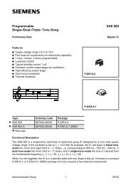
PACKAGE/ORDER I FOR ATIO<br />
CELLS<br />
V IN<br />
SW<br />
GND<br />
ORDER PART NUMBER<br />
1<br />
2<br />
3<br />
4<br />
TOP VIEW<br />
9<br />
W U<br />
DD PACKAGE<br />
8-LEAD (3mm × 3mm) PLASTIC DFN<br />
TJMAX = 125°C, θJA = 43°C/ W (NOTE 4)<br />
EXPOSED PAD (PIN 9) IS GND<br />
MUST BE SOLDERED TO PCB (NOTE 5)<br />
U<br />
<strong>LTC3490</strong>EDD LBRQ<br />
8<br />
7<br />
6<br />
5<br />
CTRL/SHDN<br />
LOBAT<br />
CAP<br />
<strong>LED</strong><br />
(Note 1)<br />
Order Options Tape and Reel: Add #TR<br />
Lead Free: Add #PBF Lead Free Tape and Reel: Add #TRPBF<br />
Lead Free Part Marking: http://www.linear.com/leadfree/<br />
Consult LTC Marketing for parts specified with wider operating temperature ranges.<br />
U<br />
Operating Temperature Range (Note 2) .. –40°C to 85°C<br />
Storage Temperature Range ................. –65°C to 125°C<br />
Lead Temperature (Soldering, 10 sec, S8) .......... 300°C<br />
CELLS 1<br />
VIN 2<br />
SW 3<br />
GND 4<br />
TOP VIEW<br />
T JMAX = 125°C, θ JA = 150°C/ W (NOTE 4)<br />
<strong>LTC3490</strong>ES8 3490<br />
ELECTRICAL CHARACTERISTICS The ● denotes specifications which apply over the full operating<br />
temperature range, otherwise specifications are TA = 25°C. VIN = 2.5V unless otherwise specified.<br />
SYMBOL PARAMETER CONDITIONS MIN TYP MAX UNITS<br />
VIN Input Supply Range 1 3.2 V<br />
VIN(START) Minimum Start-Up Voltage (Note 3) 0.9 1 V<br />
I<strong>LED</strong>(MAX) <strong>LED</strong> Drive Current VCTRL/SHDN = VIN, DD Package<br />
25°C to 85°C 330 350 370 mA<br />
–40°C to
ELECTRICAL CHARACTERISTICS The ● denotes specifications which apply over the full operating<br />
temperature range, otherwise specifications are TA = 25°C. VIN = 2.5V unless otherwise specified.<br />
<strong>LTC3490</strong><br />
SYMBOL PARAMETER CONDITIONS MIN TYP MAX UNITS<br />
IL(PMOS) Leakage Current, PMOS Switch 0.1 µA<br />
RON(PMOS) On-Resistance, PMOS Switch 0.13 Ω<br />
V IH Input High (CELLS) V IN – 0.4 V<br />
Input High (SHDN) VIN • 0.9 V<br />
V IL Input Low (CELLS) 0.4 V<br />
Input Low (SHDN) V IN • 0.2 V<br />
I IN Input Current (CTRL/SHDN, CELLS) 0.01 µA<br />
KCTRL Control Gain, I<strong>LED</strong>/VCTRL Scales <strong>Linear</strong>ity with VIN, VIN = 1V 500 mA/V<br />
RON(LOBAT) On-Resistance, LOBAT Output VIN < VIN(LOBAT) ● 300 Ω<br />
VIN(LOBAT1) Input Voltage, Low Battery, 1 <strong>Cell</strong> VCELLS = 0V ● 0.8 1.12 V<br />
VIN(LOBAT2) Input Voltage, Low Battery, 2 <strong>Cell</strong>s VCELLS = VIN ● 1.8 2.24 V<br />
V IN(UVLO2) Input Voltage, Undervoltage Lockout, V CELLS = V IN ● 1.4 1.8 V<br />
2 <strong>Cell</strong>s<br />
V IN(UVLO1) Input Voltage, Undervoltage Lockout, V CELLS = 0 V ● 0.7 0.9 V<br />
1 <strong>Cell</strong><br />
Note 1: Stresses beyond those listed under Absolute Maximum Ratings<br />
may cause permanent damage to the device. Exposure to any Absolute<br />
Maximum Rating condition for extended periods may affect device<br />
reliability and lifetime.<br />
Note 2: The <strong>LTC3490</strong> is guaranteed to meet performance specifications<br />
from 0°C to 70°C. Specifications over the –40°C to 85°C range are<br />
assured by design, characterization and correlation with statistical process<br />
controls.<br />
Note 3: The <strong>LTC3490</strong> input voltage may drop below the minimum start-up<br />
voltage once the <strong>LED</strong> voltage has risen above 2.3V.<br />
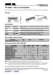
TYPICAL PERFOR A CE CHARACTERISTICS<br />
FREQUENCY (MHz)<br />
1.400<br />
1.360<br />
1.320<br />
1.280<br />
1.240<br />
1.200<br />
–50<br />
UW<br />
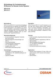
Oscillator Frequency<br />
vs Temperature I <strong>LED</strong> vs V CTRL<br />
0 50 100<br />
TEMPERATURE (°C)<br />
3490 G01<br />
I <strong>LED</strong> (mA)<br />
400<br />
350<br />
300<br />
250<br />
200<br />
150<br />
100<br />
50<br />
0<br />
0<br />
MAXIMUM<br />
Note 4: This device includes overtemperature protection intended to<br />
protect the device during momentary overload conditions. The maximum<br />
junction temperature may be exceeded when overtemperature protection<br />
is active. Continuous operation above the specified maximum operating<br />
junction temperature may result in device degradation or failure.<br />
Note 5: The Exposed Pad of the DFN package must be soldered to a<br />
PCB pad for optimum thermal conductivity. This pad must be connected<br />
to ground.<br />
MINIMUM<br />
0.2 0.4 0.6 0.8 1<br />
VCTRL/VIN (V)<br />
3490 G02<br />
I <strong>LED</strong> (mA)<br />
375<br />
350<br />
325<br />
300<br />
275<br />
I<strong>LED</strong> vs VIN<br />
V <strong>LED</strong> = 3.5V<br />
250<br />
1 1.5 2 2.5 3<br />
V IN (V)<br />
3490 G03<br />
3490fa<br />
3
<strong>LTC3490</strong><br />
TYPICAL PERFOR A CE CHARACTERISTICS<br />
PI FU CTIO S<br />
4<br />
I <strong>LED</strong> (mA)<br />
360<br />
358<br />
356<br />
354<br />
352<br />
350<br />
348<br />
346<br />
344<br />
342<br />
340<br />
2.8<br />
U U U<br />
I <strong>LED</strong> vs V <strong>LED</strong><br />
V IN = 2.4V<br />
CELLS (Pin 1): A logic input to set the low-battery and<br />
undervoltage shutdown thresholds. A logic low (tied to<br />
GND) will set the thresholds for 1 cell. A logic high (tied to<br />
VIN) will set the thresholds for 2 cells.<br />
VIN (Pin 2): Supply Voltage.<br />
SW (Pin 3): Switch Input. Connect this pin to an external<br />
inductor from V IN.<br />
GND (Pin 4): Circuit Ground.<br />
UW<br />
3 3.2 3.4<br />
V<strong>LED</strong> (V)<br />
3.6 3.8<br />
<strong>LED</strong> (Pin 5): Output Drive Current to <strong>LED</strong>.<br />
3490 G04<br />
CAP (Pin 6): Filter Capacitor. A 4.7µF low ESR capacitor<br />
should be tied to this pin.<br />
LOBAT (Pin 7): Low active, open-drain logic output indicating<br />
a low-battery condition.<br />
4<br />
EFFICIENCY (%)<br />
CTRL/SHDN (Pin 8): Analog Control Voltage and Shutdown.<br />
When VIN • 0.2 < VCTRL < VIN • 0.9, the <strong>LED</strong> drive<br />
current varies according to the formula:<br />
I<br />
100<br />
90<br />
80<br />
70<br />
60<br />
50<br />
40<br />
30<br />
20<br />
10<br />
0<br />
0<br />
<strong>LED</strong><br />
Efficiency vs I <strong>LED</strong><br />
VIN = 2.4V<br />
VIN = 1.2V<br />
100 200<br />
I<strong>LED</strong> (mA)<br />
⎛ VCTRL<br />
⎞<br />
= 500 • ⎜ – 0. 2⎟<br />
mA<br />
⎝ V ⎠<br />
IN<br />
300 400<br />
3490 G05<br />
When VCTRL > VIN • 0.9, the <strong>LED</strong> drive current is clamped<br />
at <strong>350mA</strong>. When VCTRL < VIN • 0.2, then the part is in low<br />
power shutdown.<br />
Exposed Pad (Pin 9, DD Package): Ground. This pin must<br />
be soldered to the PCB to provide both electrical contact<br />
to ground and good thermal contact to the PCB.<br />
3490fa
W<br />
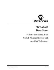
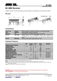
FU CTIO AL DIAGRA<br />
U U<br />
2<br />
8<br />
VIN<br />
CTRL/<br />
SHDN<br />
1 CELLS<br />
–<br />
+<br />
GATE<br />
CONTROL<br />
AND<br />
DRIVERS<br />
PWM<br />
LOGIC<br />
START-UP<br />
–<br />
+<br />
DIMMING<br />
AMP<br />
LIMIT<br />
P BODY<br />
CONTROL<br />
3<br />
OSCILLATOR<br />
I REF<br />
GND<br />
4<br />
SW<br />
SENSE<br />
AMP<br />
OVERVOLTAGE<br />
DETECT<br />
BATTERY<br />
MONITOR<br />
–<br />
+<br />
+<br />
–<br />
V REF/2<br />
SHUTDOWN<br />
CAP<br />
19.2Ω 0.1Ω<br />
250k<br />
40k<br />
<strong>LED</strong><br />
LOBAT<br />
6<br />
5<br />
7<br />
3490 FD<br />
<strong>LTC3490</strong><br />
3490fa<br />
5
<strong>LTC3490</strong><br />
OPERATIO U<br />
The <strong>LTC3490</strong> is a high efficiency, constant current source<br />
for 1W high intensity white <strong>LED</strong>s. These high intensity<br />
<strong>LED</strong>s require a fixed current of <strong>350mA</strong> with a voltage<br />
compliance of 2.8V to 4V.<br />
The <strong>LTC3490</strong> operates with 1 or 2 NiMH or alkaline cells.<br />
It functions as a boost converter with a current sense resistor<br />
providing the control feedback. If the battery voltage<br />
is greater than the required <strong>LED</strong> compliance, it will cycle<br />
off periodically to maintain the correct average current. It<br />
features a low voltage start-up circuit that will start with an<br />
input voltage of only 1V. Once the drive voltage exceeds<br />
2.3V, the circuit operates from the drive voltage.<br />
All of the loop compensation is internal; only the main filter<br />
capacitor is needed for stable operation.<br />
Dimming Function<br />
During normal operation with the CTRL/SHDN pin connected<br />
to VIN, the <strong>LED</strong> drive current is controlled at<br />
<strong>350mA</strong>. The drive current can be reduced by changing the<br />
voltage on the CTRL/SHDN pin.<br />
For VIN • 0.2 < VCTRL < VIN • 0.9, the <strong>LED</strong> current is<br />
proportional to VCTRL/VIN. This allows a simple potentiometer<br />
from VIN to control the current without sensitivity<br />
6<br />
to the battery voltage. The <strong>LED</strong> drive current is given by the<br />
formula:<br />
I<br />
<strong>LED</strong><br />
⎛ VCTRL<br />
⎞<br />
= 500 • ⎜ – 0. 2⎟<br />
mA<br />
⎝ V ⎠<br />
IN<br />
When VCTRL > VIN • 0.9, the <strong>LED</strong> drive current is clamped<br />
at <strong>350mA</strong>.<br />
Open-Circuit Protection<br />
Since this is a boost converter attempting to drive a current<br />
into the load, an open or high impedance load will cause<br />
the regulator loop to increase the output voltage in an effort<br />
to achieve regulation. To protect the device, maximum<br />
output voltage is limited to 4.7V under all conditions.<br />
Undervoltage Sense and Protection<br />
The undervoltage lockout prevents excessive inductor<br />
peak current and protects the batteries from deep discharging<br />
which can damage them. The low-battery indicator<br />
allows the end user to be made aware that the batteries<br />
are nearing the end of their useful life.<br />
3490fa
APPLICATIO S I FOR ATIO<br />
U W U U<br />
The <strong>LTC3490</strong> requires only four external components to<br />
operate: an inductor, an output capacitor, a switch and a<br />
pull-down resistor. The inductor is nominally set at 3.3µH<br />
and the capacitor at 4.7µF. Optional components include<br />
an input capacitor and dimming resistors.<br />
COMPONENT SELECTION<br />
Inductor Selection<br />
The high frequency operation of the <strong>LTC3490</strong> allows the<br />
use of small surface mount inductors. The minimum<br />
inductance value is proportional to the operating frequency<br />
and is limited by the following constraints:<br />
L<br />
f H<br />
3<br />
≥<br />
and<br />
( )<br />
V • V – V<br />
L ≥<br />
f •Ripple •V<br />
where:<br />
IN( MIN) OUT( MAX) IN( MIN)<br />
OUT( MAX)<br />
f = Operating Frequency (Hz)<br />
Ripple = Inductor Current Ripple (A)<br />
VIN(MIN) = Minimum Input Voltage (V)<br />
VOUT(MAX) = Maximum Output Voltage (V)<br />
The inductor current ripple is typically set to 20% to 40%<br />
of the inductor current.<br />
The peak inductor current is given by:<br />
I = I<br />
LPK OUT<br />
( )<br />
V + I • R – R •I<br />
VIN – RN•IIN VIN( VOUT – VIN)<br />
+<br />
2 •L•f•V H<br />
OUT OUT P N IN<br />
OUT<br />
where:<br />
VIN = Input Voltage (V)<br />
VOUT = Output Voltage (V)<br />
IOUT = <strong>LED</strong> Drive Current (A)<br />
<strong>LTC3490</strong><br />
IIN = Input Current = VOUT/VIN • IOUT (A)<br />
RP = RDSON of the PFET Switch (Ω)<br />
RN = RDSON of the NFET Switch (Ω)<br />
For high efficiency, choose an inductor with a high frequency<br />
core material, such as ferrite, to reduce core<br />
losses. The inductor should have low ESR (equivalent<br />
series resistance) to reduce the I2R losses and must be<br />
able to handle the peak inductor current at full load without<br />
saturating. In single cell applications, the inductor ESR<br />
must be below 25mΩ to keep the efficiency up and<br />
maintain output current regulation. Dual cell applications<br />
can tolerate significantly higher ESR (up to 75mΩ) with<br />
minimal efficiency degradation. Molded chokes or chip<br />
inductors usually do not have enough core to support the<br />
peak inductor currents in the 1A to 2A region. If radiated<br />
noise is an issue, use a toroid, pot core or shielded bobbin<br />
inductor to minimize radiated noise. See Table 1 for a list<br />
of suggested inductors. Look closely at the manufacturers<br />
data sheets; they specify saturation current differently.<br />
Table 1. Inductor Information<br />
INDUCTOR PART NUMBER ESR (mΩ) SATURATION CURRENT (A)<br />
TOKO A918CY-3R3M 47 1.97<br />
TYCO DN4835-3R3M 58 2.15<br />
TDK SLF7045T-3R3M2R5 20 2.5<br />
Output Capacitor Selection<br />
The output capacitor value and equivalent series resistance<br />
(ESR) are the primary factors in the output ripple.<br />
The output ripple is not a direct concern for <strong>LED</strong> drive as<br />
the <strong>LED</strong> will operate at the average current value. However<br />
the peak pulsed forward current rating of the <strong>LED</strong> must not<br />
be exceeded to avoid damaging the <strong>LED</strong>.<br />
3490fa<br />
7
<strong>LTC3490</strong><br />
APPLICATIO S I FOR ATIO<br />
The output ripple voltage has two primary components.<br />
The first is due to the value of the capacitor and is given by:<br />
8<br />
VR<br />
CAP<br />
ILPK • VIN<br />
=<br />
C•V •f<br />
OUT<br />
The second is due to the capacitor ESR:<br />
VRESR = ILPK • RESR The <strong>LED</strong> current ripple and peak pulsed current are calculated<br />
by:<br />
VR • VR<br />
IR<strong>LED</strong><br />
=<br />
R + R<br />
IR<strong>LED</strong><br />
IPPFC = IOUT+<br />
2<br />
where:<br />
CAP ESR<br />
SENSE <strong>LED</strong><br />
R SENSE = Internal Sense Resistor = 0.1Ω<br />
R<strong>LED</strong> = Dynamic Impedance of the <strong>LED</strong><br />
Low ESR capacitors should be used to minimize output<br />
ripple. Ceramic X5R or X7R type capacitors are recommended.<br />
See Table 2 for a list of component suppliers.<br />
Table 2. Capacitor Information<br />
CAPACITOR PART NUMBER DESCRIPTION<br />
TDK C2012X5R0J475K 4.7µF, 6.3V, X5R in 0805<br />
AVX 1210ZC475MAT 4.7µF, 10V, X7R in 1210<br />
Taiyo Yuden CELMK316BJ475ML 4.7µF, 10V, X7R in 1206<br />
Input Capacitor Selection<br />
Most battery-powered applications do not need an input<br />
capacitor. In supply-powered applications or battery applications<br />
with long leads to the battery, a low ESR 3.3µF<br />
capacitor reduces switching noise and peak currents.<br />
Design Example<br />
The example will use a Lumileds DS25 white <strong>LED</strong>. The key<br />
specifications are:<br />
V F (at IF= <strong>350mA</strong>) = 3.4 ±0.6V<br />
R<strong>LED</strong> = 1Ω<br />
U W U<br />
U<br />
Peak Pulsed Forward Current = 0.5A<br />
Component values will be calculated for 1 or 2 NiMH cells<br />
and assumes the end-of-charge voltage to be 0.9V per cell.<br />
The operating frequency is assumed to be 1MHz, the<br />
worst-case low frequency. The allowed inductor ripple<br />
current is 0.31A. Table 3 shows a summary of the key<br />
parameters.<br />
Table 3. Summary of Key Parameters<br />
PARAMETER 1-CELL 2-CELL UNITS<br />
LMIN 2.2 3.2 µH<br />
Choose L 3.3 3.3 µH<br />
IIN 1.56 0.78 A<br />
ILPK 1.93 0.96 A<br />
Choose C 4.7 4.7 µF<br />
Cap ESR 5 5 mΩ<br />
VRCAP 0.09 0.09 V<br />
VRESR 0.01 0.005 V<br />
IR<strong>LED</strong> 0.10 0.09 A<br />
IPPFC 0.40 0.39 A<br />
where:<br />
ILPK is the peak inductor current<br />
VRCAP is the ripple voltage due to the output capacitor<br />
value<br />
VRESR is the ripple voltage due to the output capacitor<br />
ESR<br />
IR<strong>LED</strong> is the <strong>LED</strong> current ripple<br />
IPPFC is the <strong>LED</strong> peak pulsed forward current<br />
PC Board Layout Checklist<br />
Keep the inductor and output capacitor as close to the IC<br />
as possible. Make traces as short and wide as is feasible.<br />
Parasitic resistance and inductance reduce efficiency and<br />
increase ripple.<br />
Keep resistance in the battery connections as low as<br />
possible. In single cell applications, only 0.1Ω in the<br />
battery connections will have a dramatic effect in efficiency<br />
and battery life. I2R losses can exceed 100mW and<br />
the converter operates lower on the efficiency curve.<br />
3490fa
APPLICATIO S I FOR ATIO<br />
U W U U<br />
Red Luxeon <strong>LED</strong>s<br />
The red, red-orange and amber Luxeon <strong>LED</strong>s have a lower<br />
forward voltage than the white, blue and green <strong>LED</strong>s. Since<br />
the <strong>LTC3490</strong> internal circuitry is powered from the output,<br />
it requires a minimum <strong>LED</strong> voltage of 2.5V for reliable<br />
operation. The minimum forward voltage on the red <strong>LED</strong>s<br />
TYPICAL APPLICATIO S<br />
U<br />
2 NiMH OR<br />
ALKALINE<br />
CELLS<br />
1 NiMH OR<br />
ALKALINE<br />
CELL<br />
+<br />
+<br />
+<br />
ON/OFF<br />
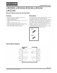
2-<strong>Cell</strong> Adjustable Amplitude <strong>LED</strong> <strong>Driver</strong><br />
1M<br />
1µF<br />
V IN<br />
CTRL/SHDN<br />
CELLS<br />
3.3µH<br />
<strong>LTC3490</strong><br />
GND<br />
SW<br />
CAP<br />
<strong>LED</strong><br />
LOBAT<br />
Soft Turn-Off <strong>LED</strong> <strong>Driver</strong><br />
ON/OFF<br />
1M<br />
V IN<br />
CTRL/SHDN<br />
CELLS<br />
3.3µH<br />
<strong>LTC3490</strong><br />
GND<br />
SW<br />
CAP<br />
<strong>LED</strong><br />
LOBAT<br />
<strong>350mA</strong><br />
4.7µF<br />
LUMI<strong>LED</strong>S<br />
LUXEON<br />
LXHL-BW02<br />
4.7µF<br />
3490 TA03<br />
LUMI<strong>LED</strong>S<br />
LUXEON<br />
LXHL-BW02<br />
3490 TA04<br />
<strong>LTC3490</strong><br />
is only 2.31V. The <strong>LTC3490</strong> requires an additional 190mV<br />
for proper operation. In non-dimming applications, this can<br />
be accomplished with a 0.6Ω resistor in series with the<br />
<strong>LED</strong>. The resistor voltage drops too low in dimming applications,<br />
so a Schottky diode is recommended to keep<br />
sufficient voltage at the output at lower currents.<br />
3490fa<br />
9
<strong>LTC3490</strong><br />
TYPICAL APPLICATIO S<br />
10<br />
1 NiMH OR<br />
ALKALINE<br />
CELL<br />
1 NiMH OR<br />
ALKALINE<br />
CELL<br />
U<br />
+<br />
+<br />
1M<br />
EFFICIENCY (%)<br />
Luxeon Red <strong>LED</strong> <strong>Driver</strong> Without Dimming<br />
ON/OFF<br />
VIN<br />
3.3µH<br />
<strong>LTC3490</strong><br />
CTRL/SHDN<br />
SW<br />
CAP<br />
<strong>LED</strong><br />
4.7µF<br />
CELLS LOBAT 0.6Ω<br />
1M<br />
GND<br />
LUMI<strong>LED</strong>S<br />
LUXEON<br />
LXHL-BD03<br />
90<br />
80<br />
70<br />
60<br />
50<br />
40<br />
30<br />
20<br />
10<br />
Luxeon Red <strong>LED</strong> <strong>Driver</strong> with Dimming<br />
0<br />
1<br />
ON/OFF<br />
VIN<br />
CTRL/SHDN<br />
CELLS<br />
RESISTOR<br />
3.3µH<br />
<strong>LTC3490</strong><br />
GND<br />
SW<br />
CAP<br />
<strong>LED</strong><br />
LOBAT<br />
Efficiency vs V IN with Red <strong>LED</strong><br />
SCHOTTKY<br />
1.5 2<br />
VIN (V)<br />
2.5<br />
3490 G06<br />
4.7µF<br />
3490 TA06<br />
MBRM120E<br />
LUMI<strong>LED</strong>S<br />
LUXEON<br />
LXHL-BD03<br />
3<br />
3490 TA07<br />
3490fa
PACKAGE DESCRIPTIO<br />
3.5 ±0.05<br />
2.15 ±0.05<br />
1.65 ±0.05<br />
(2 SIDES)<br />
0.25 ± 0.05<br />
0.50<br />
BSC<br />
2.38 ±0.05<br />
(2 SIDES)<br />
U<br />
RECOMMENDED SOLDER PAD PITCH AND DIMENSIONS<br />
.245<br />
MIN<br />
.030 ±.005<br />
TYP<br />
.008 – .010<br />
(0.203 – 0.254)<br />
.050 BSC<br />
0.675 ±0.05<br />
PACKAGE<br />
OUTLINE<br />
DD Package<br />
8-Lead Plastic DFN (3mm × 3mm)<br />
(Reference LTC DWG # 05-08-1698)<br />
PIN 1<br />
TOP MARK<br />
(NOTE 6)<br />
3.00 ±0.10<br />
(4 SIDES)<br />
S8 Package<br />
8-Lead Plastic Small Outline (Narrow .150 Inch)<br />
(Reference LTC DWG # 05-08-1610)<br />
RECOMMENDED SOLDER PAD LAYOUT<br />
.010 – .020<br />
× 45°<br />
(0.254 – 0.508)<br />
.016 – .050<br />
(0.406 – 1.270)<br />
NOTE:<br />
INCHES<br />
1. DIMENSIONS IN<br />
(MILLIMETERS)<br />
.045 ±.005<br />
.160 ±.005<br />
Information furnished by <strong>Linear</strong> <strong>Technology</strong> Corporation is believed to be accurate and reliable.<br />
However, no responsibility is assumed for its use. <strong>Linear</strong> <strong>Technology</strong> Corporation makes no representation<br />
that the interconnection of its circuits as described herein will not infringe on existing patent rights.<br />
1.65 ± 0.10<br />
(2 SIDES)<br />
R = 0.115<br />
TYP<br />
5<br />
<strong>LTC3490</strong><br />
0.38 ± 0.10<br />
4<br />
1<br />
0.200 REF<br />
0.75 ±0.05<br />
0.25 ± 0.05<br />
0.50 BSC<br />
2.38 ±0.10<br />
(2 SIDES)<br />
0.00 – 0.05<br />
BOTTOM VIEW—EXPOSED PAD<br />
NOTE:<br />
1. DRAWING TO BE MADE A JEDEC PACKAGE OUTLINE M0-229 VARIATION OF (WEED-1)<br />
2. DRAWING NOT TO SCALE<br />
3. ALL DIMENSIONS ARE IN MILLIMETERS<br />
4. DIMENSIONS OF EXPOSED PAD ON BOTTOM OF PACKAGE DO NOT INCLUDE<br />
MOLD FLASH. MOLD FLASH, IF PRESENT, SHALL NOT EXCEED 0.15mm ON ANY SIDE<br />
5. EXPOSED PAD SHALL BE SOLDER PLATED<br />
6. SHADED AREA IS ONLY A REFERENCE FOR PIN 1 LOCATION<br />
ON TOP AND BOTTOM OF PACKAGE<br />
0°– 8° TYP<br />
.228 – .244<br />
(5.791 – 6.197)<br />
.053 – .069<br />
(1.346 – 1.752)<br />
.014 – .019<br />
(0.355 – 0.483)<br />
TYP<br />
2. DRAWING NOT TO SCALE<br />
3. THESE DIMENSIONS DO NOT INCLUDE MOLD FLASH OR PROTRUSIONS.<br />
MOLD FLASH OR PROTRUSIONS SHALL NOT EXCEED .006" (0.15mm)<br />
.189 – .197<br />
(4.801 – 5.004)<br />
NOTE 3<br />
8 7 6 5<br />
1 2 3 4<br />
.150 – .157<br />
(3.810 – 3.988)<br />
NOTE 3<br />
.004 – .010<br />
(0.101 – 0.254)<br />
.050<br />
(1.270)<br />
BSC<br />
SO8 0303<br />
8<br />
(DD8) DFN 1203<br />
3490fa<br />
11
<strong>LTC3490</strong><br />
TYPICAL APPLICATIO U<br />
RELATED PARTS<br />
PART NUMBER DESCRIPTION COMMENTS<br />
LT ® 1618 Constant Current, Constant Voltage 1.4MHz, V IN: 1.6V to 18V, V OUT(MAX) = 34V, I Q = 1.8mA, I SD < 1µA, MS/EDD<br />
High Efficiency Boost Regulator Packages<br />
LT1932 Constant Current, 1.2MHz, High Efficiency White VIN: 1V to 10V, VOUT(MAX) = 34V, IQ = 1.2mA, ISD < 1µA, ThinSOT Packages<br />
<strong>LED</strong> Boost Regulator<br />
LT1937 Constant Current, 1.2MHz, High Efficiency White V IN: 2.5V to 10V, V OUT(MAX) = 34V, I Q = 1.9mA, I SD < 1µA, ThinSOT TM /SC70<br />
<strong>LED</strong> Boost Regulator Packages<br />
LTC3205 High Efficiency, Multi-Display <strong>LED</strong> Controller V IN: 2.8V to 4.5V, V OUT(MAX) = 6V, I Q = 50µA, I SD < 1µA, QFN24 Package<br />
LTC3216 1A Low Noise, High Current <strong>LED</strong> Charge Pump with VIN: 2.9V to 4.4V, VOUT(MAX) = 5.5V, IQ = 300µA, ISD < 2.5µA, DFN Package<br />
Independent Flash/Torch Current Control<br />
LTC3402 2A, 3MHz Micropower Synchronous Boost Converter VIN: 0.85V to 5V, VOUT(MAX) = 5V, IQ = < 38µA, ISD < 1µA,<br />
MS/EDD Packages<br />
LTC3453 500mA Synchronous Buck-Boost High Current <strong>LED</strong> V IN: 2.7V to 5.5V, V OUT(MAX) = 5.5V, I Q = 0.6mA, I SD < 6µA, QFN Package<br />
<strong>Driver</strong> in QFN<br />
LT3465/LT3465A Constant Current, 1.2MHz/2.7MHz, High Efficiency<br />
White <strong>LED</strong> Boost Regulator with Integrated Schottky<br />
Diode<br />
VIN: 2.7V to 16V, VOUT(MAX) = 34V, IQ = 1.9mA, ISD < 1µA, ThinSOT Package<br />
LT3466 Dual Constant Current, 2MHz, High Efficiency<br />
White <strong>LED</strong> Boost Regulator with Integrated Schottky<br />
Diode<br />
VIN: 2.7V to 24V, VOUT(MAX) = 40V, IQ = 5mA, ISD < 16µA, DFN Package<br />
LT3479 3A, Full-Featured DC/DC Converter with Soft-Start VIN: 2.5V to 24V, VOUT(MAX) = 40V, IQ = 6.5mA, ISD < 1µA, DFN/TSSOP<br />
and Inrush Current Protection Packages<br />
ThinSOT is a trademark of <strong>Linear</strong> <strong>Technology</strong> Corporation.<br />
12<br />
1 NiMH OR<br />
ALKALINE<br />
CELL<br />
<strong>Linear</strong> <strong>Technology</strong> Corporation<br />
1630 McCarthy Blvd., Milpitas, CA 95035-7417<br />
(408) 432-1900 ● FAX: (408) 434-0507 ● www.linear.com<br />
<strong>LED</strong> <strong>Driver</strong> Drops to 20% Amplitude on Low-Battery Detect<br />
+<br />
1M<br />
ON/OFF<br />
1M<br />
432k<br />
V IN<br />
CTRL/SHDN<br />
CELLS<br />
3.3µH<br />
<strong>LTC3490</strong><br />
GND<br />
SW<br />
CAP<br />
<strong>LED</strong><br />
LOBAT<br />
<strong>350mA</strong>/70mA<br />
4.7µF<br />
LUMI<strong>LED</strong>S<br />
LUXEON<br />
LXHL-BWO2<br />
3490 TA05<br />
3490fa<br />
LT 0606 REV A • PRINTED IN THE USA<br />
© LINEAR TECHNOLOGY CORPORATION 2005