Programmable Single-/Dual-/Triple- Tone Gong SAE 800
Programmable Single-/Dual-/Triple- Tone Gong SAE 800
Programmable Single-/Dual-/Triple- Tone Gong SAE 800
- No tags were found...

You also want an ePaper? Increase the reach of your titles
YUMPU automatically turns print PDFs into web optimized ePapers that Google loves.
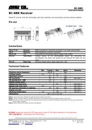
<strong>Programmable</strong><strong>Single</strong>-/<strong>Dual</strong>-/<strong>Triple</strong>- <strong>Tone</strong> <strong>Gong</strong>Preliminary Data<strong>SAE</strong> <strong>800</strong>Bipolar ICFeatures● Supply voltage range 2.8 V to 18 V● Few external components (no electrolytic capacitor)● 1 tone, 2 tones, 3 tones programmable● Loudness control● Typical standby current 1 µA● Constant current output stage (no oscillation)● High-efficiency power stage● Short-circuit protection● Thermal shutdownP-DIP-8-4P-DSO-8-1Type Ordering Code Package▼ <strong>SAE</strong> <strong>800</strong> Q67000-A8339 P-DIP-8-4▼ <strong>SAE</strong> <strong>800</strong> G Q67000-A8340 P-DSO-8-1 (SMD)▼ New typeFunctional DescriptionThe <strong>SAE</strong> <strong>800</strong> is a single-tone, dual-tone or triple-tone gong IC designed for a very wide supplyvoltage range. If the oscillator is set to f 0 = 13.2 kHz for example, the IC will issue in triple-tonemodethe minor and major third e 2 – C sharp – a, corresponding to 660 Hz – 550 Hz – 440 Hz, indual-tone-mode the minor third e 2 – C sharp, and in single-tone-mode the tone e 2 (derived fromthe fundamental frequency f 0 ; f 1 = f 0 / 20, f 2 = f 0 / 24, f 3 = f 0 / 30).When it is not triggered, the IC is in a standby state and only draws a few µA. It comes in a compactP-DIP-8-1 or P-DSO-8-1 (SMD) package and only requires a few external components.Semiconductor Group 1 09.94
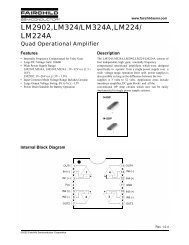
<strong>SAE</strong> <strong>800</strong><strong>SAE</strong> <strong>800</strong><strong>SAE</strong> <strong>800</strong> GPin Configuration(top view)Pin Definitions and FunctionsPin Symbol Function1 GND Ground2 Q Output3 V S Supply Voltage4 L Loudness Control5 R OSC Oscillator Resistor6 C OSC Oscillator Capacitor7 E2 Trigger 2 (dual tone)8 E1 Trigger 1 (single tone)Functional Description (cont’d)An RC combination is needed to generate the fundamental frequency (pin R OSC , C OSC ). The volumecan be adjusted with another resistor (pin L). The loudspeaker must be connected directly betweenthe output Q and the power supply V S . The current-sink principle combined with an integratedthermal shutdown (with hysteresis) makes the IC overload-protected and shortcircuit-protected.There are two trigger pins (E1, E2) for setting single-tone, dual-tone or triple-tone mode.Semiconductor Group 2
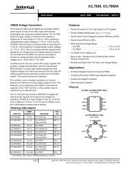
<strong>SAE</strong> <strong>800</strong>Block DiagramSemiconductor Group 3
<strong>SAE</strong> <strong>800</strong>Digital / Analog Converter, Loudness and Junction ControlThe DAC converts the 4-bit words from the logic into the appropriate staircase currents with theparticular tone frequency. The sum current I I drives the following current amplifier. The loudnessgenerator produces the DAC reference current I L for all three tones. This requires connecting anexternal resistor to ground. The chip temperature is monitored by the junction control. Attemperatures of more then approx. 170 ˚C the stop input will switch the output currentI I to zero. Theoutput current is enabled again once the chip has cooled down to approx. 150 ˚C.Current AmplifierThe current amplifier with a gain of 1600 boosts the current I I from approx. 470 µA maximum toapprox. 750 mA maximum. The output stage consists of an NPN transistor with its emitter on powerGND and collector on pin Q.The current control insures that the output stage only conducts defined currents. In conjunction withthe integrated thermal shutdown, this makes the configuration shortcircuit-protected within widelimits. Because of the absence of feedback the circuit is also extremely stable and thereforeuncritical in applications. Resistor R L on pin L sets the output voltage swing. This assumes that theresistive component of the loudspeaker impedance R Q responds similarly as the resistance R L .The output amplitude of the current I I reaches the maximum I Imax ≅ 3 x V L / R L at a time t of 2.33 s(only 3 tone mode), so R L has to be scaled for this point.The following applies:I Q = I Imax x B = (V S – V sat ) / R Q ≈ 0.8 V S / R Q3 x B x (V L / R L ) ≈ 0.8 V S / R Qthe result is:R L = R Q x 3 x B x (V L / 0.8 V S ) with: B = 1600R L = R Q x K x (V L / 0.8 V S ) with: K = 4<strong>800</strong>Semiconductor Group 6
<strong>SAE</strong> <strong>800</strong>Application Hints and Application Circuit1) Loudness Resistor (max. Load Current of 3-<strong>Tone</strong> Signal with Ensured Ratio of Amplitudes)0.8 V S / R Q ≈ (V L / R L ) x KR L = (V L / 0.8 V S ) x R Q x K; K = 4<strong>800</strong>Example: R Q = 8 Ω; V S = 5 V; V L = 1.2 VR L = (1.2 / 4) x 8 Ω x 4<strong>800</strong> ≈ 12 kΩ2) Oscillator Elements R R , C Cf = 5 / 8 x 1 / (R R x C C )Example: f = 13.2 kHz; C C = 4.7 nFR R = 5 / (8 x 13.2 x 4.7) x 10 6 Ω≈ 10 kΩThe following is a typical application circuitApplication CircuitSemiconductor Group 7
<strong>SAE</strong> <strong>800</strong>Absolute Maximum RatingsParameter Symbol Limit Values Unitmin. max.Supply voltage V S – 0.3 24 VInput voltage at E1, E2 V E1, E2 – 5 24 VCurrent at output QCurrent at input pins E1, E2Current at pin R OSCCurrent at pin LCurrent at pin C OSCI Q – 50I E1, E2 – 2I RIL7503mAmAI C – 200 200 µA– 300– 300200200µAµAJunction temperature T j – 50 150 ˚CStorage temperature T stg – 50 150 ˚COperating RangeSupply voltage V S 2.8 18 VJunction temperature T j – 25 125 ˚COscillator frequency at C OSC f C 100 kHzCurrent at pin R OSCCurrent for test mode at pin LCurrent at pin L– 200I RI L – 200I R 90– 10110– 10Input voltage at E1, E2 V E1, E2 – 4 18 VThermal resistancejunction-air (P-DIP-8-4)junction-air (P-DSO-8-1)R th JA100R th JA 180µAµAµAK/WK/WSemiconductor Group 8
<strong>SAE</strong> <strong>800</strong>CharacteristicsT j = – 25 to 125˚C; V S = 2.8 to 18 VParameter Symbol Limit Values Unit Testmin. typ. max.ConditionSupply SectionStandby currentQuiescent current; pin L openI St1I Qu 51010µAmAOutput SectionPeak output power (tone 3)V S = 2.8 V; R Q = 4 Ω; R L = 8.2 kΩV S = 2.8 V; R Q = 8 Ω; R L = 18 kΩV S = 5.0 V; R Q = 8 Ω; R L = 10 kΩV S = 5.0 V; R Q = 16 Ω; R L = 18 kΩV S = 12 V; R Q = 50 Ω; R L = 33 kΩP Q 250P Q 125P Q 450P Q 225P Q 450330165600300600mWmWmWmWmWAOutput level differences:tone 1 to 3tone 2 to 3a 13 – 1a 23 – 111dBdBA 1)A 2)Biasing SectionVoltage at pin R OSC ; R R = 10 kΩVoltage at pin L; R L = 10 kΩV R1.2V L 1.2VVOscillator SectionAmplitudeFrequency R R = 10 kΩ;C C = 4.7 nFOscill. drift vs. temperatureOscill. drift vs. supply voltage∆V Cf 0D T – 3D V0.513.21+ 3VkHz10 -4 /K10 -3 /KInput SectionTriggering voltage at E1, E2Triggering current at E1, E2Noise voltage immunity at E1, E2Triggering delay at f 0 = 13.2 kHzV E1 , E2 1.6I E1 , E2 100V E1 , E2t dT 20.310VµAVms1) a 13 = 20 x log (M1 / (0.67 x M3))2) a 23 = 20 x log (M2 / (0.89 x M3))Semiconductor Group 9
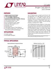
<strong>SAE</strong> <strong>800</strong>Output Peak Voltage V Q versusLoudness-Current I LMax. Output Power P Q versusLoudness-Current I LPower Dissipation P v of Output Stageversus Loudness-Current I LPeak Current I Q versus Loudness-Current I L*) Note that I Q = f (I L ) varies between 0 and K ⋅ I L during tone sequence. Thereby the maximum of the powerdissipation during the tone sequence is the maximum of P v (in diagram) between I L = 0 and chosen I L = V L /R L .Semiconductor Group 10
<strong>SAE</strong> <strong>800</strong>Output Peak Voltage V Q versusLoudness-Current I LMax. Output Power P Q versusLoudness-Current I LPower Dissipation P v of Output Stageversus Loudness-Current I LPeak Current I Q versus Loudness-Current I L*) Note that I Q = f (I L ) varies between 0 and K ⋅ I L during tone sequence. Thereby the maximum of the powerdissipation during the tone sequence is the maximum of P v (in diagram) between I L = 0 and chosen I L = V L /R L .Semiconductor Group 11
<strong>SAE</strong> <strong>800</strong>Circuit for <strong>SAE</strong> <strong>800</strong> Application in Home Chime Installation Utilizing AC and DC Triggeringfor 1, 2 or 3 <strong>Tone</strong> Chime; Adjustable VolumePCB layout information: Because of the peak currents at V S , Q and GND the lines should bedesigned in a flatspread way or as star pattern.Semiconductor Group 12
<strong>SAE</strong> <strong>800</strong>Circuit for <strong>SAE</strong> <strong>800</strong> Application in Home Chime Installation for Operation without BatterySemiconductor Group 13
<strong>SAE</strong> <strong>800</strong>Package OutlinesPlastic-Package, P-DIP-8-4(Plastic <strong>Dual</strong> In-Line Package)GPD05583Plastic-Package, P-DSO-8-1 (SMD)(Plastic <strong>Dual</strong> Small Outline)GPS05121SMD = Surface Mounted DeviceDimensions in mmSemiconductor Group 14
This datasheet has been download from:www.datasheetcatalog.comDatasheets for electronics components.