TX-SAW / 433 s-Z Transmitter - Ottomat
TX-SAW / 433 s-Z Transmitter - Ottomat
TX-SAW / 433 s-Z Transmitter - Ottomat

You also want an ePaper? Increase the reach of your titles
YUMPU automatically turns print PDFs into web optimized ePapers that Google loves.
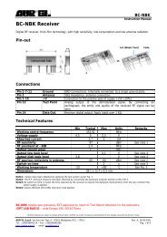
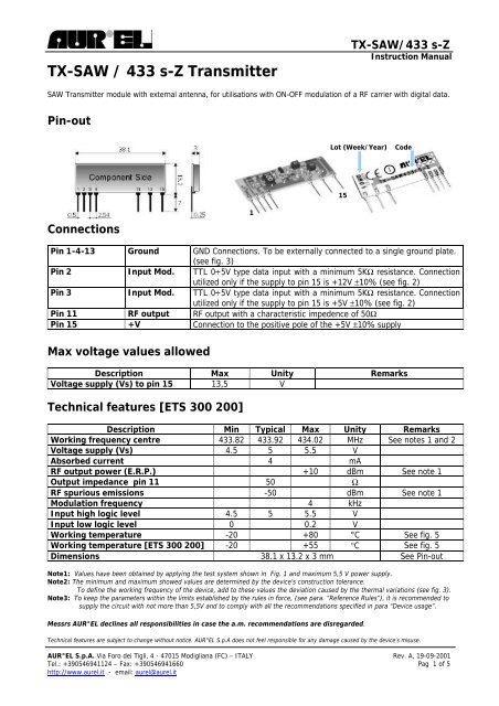
<strong>TX</strong>-<strong>SAW</strong> / <strong>433</strong> s-Z <strong>Transmitter</strong><strong>TX</strong>-<strong>SAW</strong>/<strong>433</strong> s-ZInstruction Manual<strong>SAW</strong> <strong>Transmitter</strong> module with external antenna, for utilisations with ON-OFF modulation of a RF carrier with digital data.Pin-outLot (Week/Year)Code15Connections1Pin 1-4-13 Ground GND Connections. To be externally connected to a single ground plate.(see fig. 3)Pin 2 Input Mod. TTL 0÷5V type data input with a minimum 5KΩ resistance. Connectionutilized only if the supply to pin 15 is +12V ±10% (see fig. 2)Pin 3 Input Mod. TTL 0÷5V type data input with a minimum 5KΩ resistance. Connectionutilized only if the supply to pin 15 is +5V ±10% (see fig. 2)Pin 11 RF output RF output with a characteristic impedence of 50ΩPin 15 +V Connection to the positive pole of the +5V ±10% supplyMax voltage values allowedDescription Max Unity RemarksVoltage supply (Vs) to pin 15 13,5 VTechnical features [ETS 300 200]Description Min Typical Max Unity RemarksWorking frequency centre <strong>433</strong>.82 <strong>433</strong>.92 434.02 MHz See notes 1 and 2Voltage supply (Vs) 4.5 5 5.5 VAbsorbed current 4 mARF output power (E.R.P.) +10 dBm See note 1Output impedance pin 11 50 ΩRF spurious emissions -50 dBm See note 1Modulation frequency 4 kHzInput high logic level 4.5 5 5.5 VInput low logic level 0 0.2 VWorking temperature -20 +80 °C See fig. 5Working temperature [ETS 300 200] -20 +55 °C See fig. 5Dimensions 38.1 x 13.2 x 3 mm See Pin-outNote1: Values have been obtained by applying the test system shown in Fig. 1 and maximum 5,5 V power supply.Note2: The minimum and maximum showed values are determined by the device’s construction tolerance.To define the working frequency of the device, add to these values the deviation caused by the thermal variations (see fig. 3).Note3: To keep the parameters within the limits established by the rules in force, (see para. “Reference Rules”), it is recommended tosupply the circuit with not more than 5,5V and to comply with all the recommendations specified in para “Device usage”.Messrs AUR°EL declines all responsibilities in case the a.m. recommendations are disregarded.Technical features are subject to change without notice. AUR°EL S.p.A does not feel responsible for any damage caused by the device’s misuse.AUR°EL S.p.A. Via Foro dei Tigli, 4 - 47015 Modigliana (FC) – ITALY Rev. A, 19-09-2001Tel.: +390546941124 – Fax: +390546941660 Pag 1 of 5http://www.aurel.it - email: aurel@aurel.it
The declared technical features have been obtained by applying the following testing system:<strong>TX</strong>-<strong>SAW</strong>/<strong>433</strong> s-ZInstruction ManualFig. 1+5V DCPowerSupplierSquare wave generator :4 KHz frequencyOut Level 0‚5VRF 50 W InputSpectrumanalyzerPin 3<strong>TX</strong>-<strong>SAW</strong>/<strong>433</strong> s-ZPin 1150 ÙcoaxialcableconnectionDevice usageIn order to obtain the performances described in the technical specifications and to comply with theoperating conditions, which characterize the Certification, the transmitter has to be mounted on a printedcircuit, and keep into consideration what follows:5V dc supply1. The transmitter must be supplied by a very low voltage source, safely protected against short circuits.2. Maximum voltage variations allowed: ± 0,5 V.3. De-coupling, next to the transmitter, by means of a minimum 100.000 pF ceramic capacitor.Ground1. It must surround at the best the welding area of the transmitter. The circuit must be double layer, withthroughout vias to the ground planes, approximately each 15 mm.2. It must be properly dimensioned, especially in the antenna connection area, in case a radiating whipantenna is fitted in it (an area of approximately 50 mm radius is suggested).Technical features are subject to change without notice. AUR°EL S.p.A does not feel responsible for any damage caused by the device’s misuse.AUR°EL S.p.A. Via Foro dei Tigli, 4 - 47015 Modigliana (FC) – ITALY Rev. A, 19-09-2001Tel.: +390546941124 – Fax: +390546941660 Pag 2 di 5http://www.aurel.it - email: aurel@aurel.it
<strong>TX</strong>-<strong>SAW</strong>/<strong>433</strong> s-ZInstruction ManualFig. 250 Ohm line1. It must be the shortest as possible.2. 1,8 mm wide for 1 mm thick FR4 printed circuits and 2,9 mm wide for 1,6 mm thick FR4 printed circuits.It must be kept 2 mm away from the ground circuit on the same side.3. On the opposite side a ground circuit area must be present.Antenna connection1. It may be utilized as the direct connection point for the radiating whip antenna.2. It can bear the connection of the central wire of a 50 Ω coaxial cable. Be sure that the braid is welded tothe ground in a close point.Antenna1. A whip antenna, 16,5 mm long and approximately 1 mm dia, brass or copper wire made, must beconnected to the RF output of the transmitter (pin 11), (see fig. 2).2. The antenna body must be keep straight as much as possible and it must be free from other circuits ormetal parts (5 cm minimum suggested distance.)3. It can be utilized either vertically or horizontally, provided that a good ground plane surrounds theconnection point between antenna and transmitter output.N.B: As an alternative to the a.m. antenna it is possible to fit the whip model manufactured byAUR°EL (see related Data Sheet and Application Notes).By fitting whips too different from the described ones, the EEC Certification is not assured.Other components1. Keep the transmitter separate from all other components of the circuit (more than 5 mm).Technical features are subject to change without notice. AUR°EL S.p.A does not feel responsible for any damage caused by the device’s misuse.AUR°EL S.p.A. Via Foro dei Tigli, 4 - 47015 Modigliana (FC) – ITALY Rev. A, 19-09-2001Tel.: +390546941124 – Fax: +390546941660 Pag 3 di 5http://www.aurel.it - email: aurel@aurel.it
<strong>TX</strong>-<strong>SAW</strong>/<strong>433</strong> s-ZInstruction Manual2. Keep particularly far away and shielded all microprocessors and their clock circuits.3. Do not fit components around the 50 Ohm line. Keep them at least at 5 mm distance.4. If the Antenna Connection is directly used for a radiating whip connection, keep at least 5 cm radius freearea. In case a 50 Ω impedance coaxial cable is connected, then 5 mm radius will suffice.Reference RulesThe <strong>TX</strong>-<strong>SAW</strong>/<strong>433</strong> s-Z transmitter complies with the EU Rules ETS 300-220, with a 5,5V max. supply. Theequipment has been tested according to rule EN 60950 and it can be utilized inside a special insulatedhousing that assures its compliance with the above mentioned rule. The transmitter must be supplied by avery low voltage source, safely protected against short circuits.The use of the transmitter module is foreseen inside housings that assure the overcoming of the rules EN61000 not directly applicable to the module itself. In particular, it is left at the User’s care, the insulation ofthe external antenna connection, and of the antenna itself, since the RF output of the transmitter is not builtto directly bear the electrostatic charges foreseen by the EN 61000-4-2 rules.CEPT 70-03 RecommendationIn order to comply with such rule, the device must be used only for a 10% of an hourly duty-cycle, (thatmeans 6 minutes of utilisation over 60). The device utilisation inside the italian territory is governed by theCodice Postale and Telecomunicazioni rules in force (art. no. 334 and subsequents).B<strong>TX</strong>-<strong>SAW</strong>/<strong>433</strong> s-Z module was previously BZT approved by mean of Test Report obtained c/o thelaboratory: SENTON GmbH - Äussere Frühlingstrasse 45 D – 94315 STRAUBINTechnical features are subject to change without notice. AUR°EL S.p.A does not feel responsible for any damage caused by the device’s misuse.AUR°EL S.p.A. Via Foro dei Tigli, 4 - 47015 Modigliana (FC) – ITALY Rev. A, 19-09-2001Tel.: +390546941124 – Fax: +390546941660 Pag 4 di 5http://www.aurel.it - email: aurel@aurel.it
Reference curves<strong>TX</strong>-<strong>SAW</strong>/<strong>433</strong> s-ZInstruction ManualFig.3 Temperature - Frequency deltaDelta F [KHz]100806040200-20-40-60-80-100F 0 =<strong>433</strong>.92±100KHz-20 -10 0 10 20 30 40 50 60 70 80Temperature [°C]The curve has been obtained by the testing system shown in Fig.1.5V Power supplyFig.4 Temperature - Output power deltaOutput power delta [dB]210-1-2-20 -10 0 10 20 30 40 50 60 70 80Temperature [°C]The curve has been obtained by the testing system shown in Fig.15V supply, RF output <strong>433</strong>,92MHz, ±100 kHz, output power 8dBm ±2dBTechnical features are subject to change without notice. AUR°EL S.p.A does not feel responsible for any damage caused by the device’s misuse.AUR°EL S.p.A. Via Foro dei Tigli, 4 - 47015 Modigliana (FC) – ITALY Rev. A, 19-09-2001Tel.: +390546941124 – Fax: +390546941660 Pag 5 di 5http://www.aurel.it - email: aurel@aurel.it