

Linear Motor Actuators GLM10,15,20,25 - Thk.com
Linear Motor Actuators GLM10,15,20,25 - Thk.com
Linear Motor Actuators GLM10,15,20,25 - Thk.com

You also want an ePaper? Increase the reach of your titles
YUMPU automatically turns print PDFs into web optimized ePapers that Google loves.
54<br />
276<br />
<strong>25</strong><br />
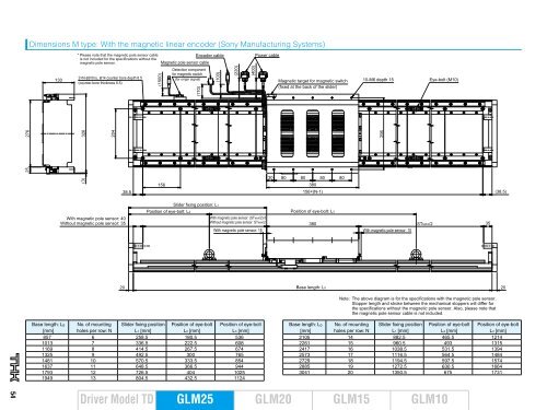
Dimensions M type: With the magnetic linear encoder (Sony Manufacturing Systems)<br />
130<br />
* Please note that the magnetic pole sensor cable<br />
Encoder cable Power cable<br />
is not included for the specifications without the<br />
magnetic pole sensor. Magnetic pole sensor cable<br />
Detection <strong>com</strong>ponent<br />
2×N-ø9 thru, ø14 counter bore depth 8.5<br />
(counter-bore thickness 6.5)<br />
326<br />
(3)<br />
<strong>20</strong>4<br />
With magnetic pole sensor: 40<br />
Without magnetic pole sensor: 35<br />
38.5<br />
Base length: L0 No. of mounting Slider fixing position Position of eye-bolt Position of eye-bolt<br />
[mm] holes per row: N L1 [mm]<br />
L2 [mm]<br />
L3 [mm]<br />
857 6 <strong>25</strong>8.5 180.5 536<br />
1013 7 336.5 222.5 608<br />
1169 8 414.5 267.5 674<br />
13<strong>25</strong> 9 492.5 300 765<br />
1481 10 570.5 333.5 854<br />
1637 11 648.5 366.5 944<br />
1793 12 726.5 404 10<strong>25</strong><br />
1949 13 804.5 432.5 1124<br />
Driver Model TD<br />
(<strong>15</strong>00)<br />
<strong>15</strong>6<br />
for magnetic switch<br />
(for origin signal)<br />
Position of eye-bolt: L2<br />
(170)<br />
GLM<strong>25</strong><br />
(100)<br />
Slider fixing position: L1<br />
(2<strong>20</strong>)<br />
(400)<br />
Magnetic target for magnetic switch<br />
(fixed at the back of the slider)<br />
30 80 80 80 80<br />
380<br />
<strong>15</strong>6×(N-1) (38.5)<br />
Position of eye-bolt: L3<br />
10-M6 depth <strong>15</strong><br />
With magnetic pole sensor: (STMAX/2)-5<br />
Without magnetic pole sensor: STMAX/2<br />
380<br />
With magnetic pole sensor: <strong>15</strong> With magnetic pole sensor: 10<br />
<strong>20</strong> Base length: L0<br />
<strong>20</strong><br />
STMAX/2<br />
Note: The above diagram is for the specifications with the magnetic pole sensor.<br />
Stopper length and stroke between the mechanical stoppers will differ for<br />
the specifications without the magnetic pole sensor. Also, please note that<br />
the magnetic pole sensor cable is not included.<br />
Base length: L0 No. of mounting Slider fixing position Position of eye-bolt Position of eye-bolt<br />
[mm] holes per row: N L1 [mm]<br />
L2 [mm]<br />
L3 [mm]<br />
2105 14 882.5 465.5 1214<br />
2261 <strong>15</strong> 960.5 493 13<strong>15</strong><br />
2417 16 1038.5 531.5 1394<br />
<strong>25</strong>73 17 1116.5 564.5 1484<br />
2729 18 1194.5 597.5 <strong>15</strong>74<br />
2885 19 1272.5 630.5 1664<br />
3041 <strong>20</strong> 1350.5 675 1731<br />
GLM<strong>20</strong> GLM<strong>15</strong> <strong>GLM10</strong><br />
296<br />
Eye-bolt (M10)<br />
35
