Critical Issues in Nanofluids Research and Application ... - Kostic
Critical Issues in Nanofluids Research and Application ... - Kostic
Critical Issues in Nanofluids Research and Application ... - Kostic

Create successful ePaper yourself
Turn your PDF publications into a flip-book with our unique Google optimized e-Paper software.
CRITICAL ISSUES IN NANOFLUIDS RESEARCH AND APPLICATION POTENTIALS<br />
Milivoje M. <strong>Kostic</strong> 1<br />
Department of Mechanical Eng<strong>in</strong>eer<strong>in</strong>g<br />
Northern Ill<strong>in</strong>ois University<br />
DeKalb, IL 60115-2854<br />
ABSTRACT<br />
The objective here is to present this author’s views on selected nanofluids’ critical research issues <strong>and</strong><br />
application potentials, as related to the research accomplished <strong>and</strong> a number of hypothesis posed by<br />
different <strong>in</strong>vestigators – the goal is to shed some light on the subject as opposed to merely ‘generat<strong>in</strong>g<br />
heat’. There are significant discrepancies among the experimental data available, as well as between the<br />
experimental f<strong>in</strong>d<strong>in</strong>gs <strong>and</strong> the theoretical model predictions, related to nanofluids thermo-physical<br />
characteristics. Oddly, there are more hypothetical theories proposed than reliable experimental results to<br />
verify those theoretical models. The nanofluids were hyped-up <strong>in</strong> the past, but it would be a mistake to<br />
hype-down nanofluids now <strong>and</strong> make premature judgments based on <strong>in</strong>consistent <strong>and</strong> <strong>in</strong>complete research<br />
to-date.<br />
Regardless of ever-<strong>in</strong>creas<strong>in</strong>g number of research studies <strong>in</strong> this area, the basic research of<br />
convenience (repetition of similar experimentation with unstable nanofluids) rema<strong>in</strong>s <strong>in</strong> the <strong>in</strong>itial stage;<br />
the promis<strong>in</strong>g nanofluids are still to be developed <strong>and</strong> results are still to be experimentally re-confirmed<br />
<strong>and</strong> established.<br />
Development of many <strong>in</strong>dustrial <strong>and</strong> new technologies is limited by exist<strong>in</strong>g thermal management,<br />
<strong>and</strong> need for enhanced heat transfer <strong>and</strong> high-performance cool<strong>in</strong>g. <strong>Nanofluids</strong>, stable colloidal mixtures<br />
of nanoparticles (<strong>in</strong>clud<strong>in</strong>g nanorods, nanofibers, nanotubes, nanosheets, <strong>and</strong> functional nanocomposites,<br />
even nano-droplets <strong>and</strong> nano-bubbles) <strong>in</strong> common fluids, have a potential to meet these <strong>and</strong> many other<br />
challenges. Colloidal nano-mixtures with functionally-stable <strong>and</strong> active-like nanostructures that may selfadjust<br />
to the process conditions, require systematic surface-chemistry study <strong>and</strong> enhancements (coat<strong>in</strong>gs<br />
with functional layers, surfactants, etc.), <strong>in</strong> addition to <strong>in</strong>vestigation of thermo-physical characteristics<br />
<strong>and</strong> phenomena.<br />
A comprehensive, systematic <strong>and</strong> <strong>in</strong>terdiscipl<strong>in</strong>ary experimental research program is necessary to<br />
study, underst<strong>and</strong> <strong>and</strong> resolve critical issues <strong>in</strong> nanofluids research to date. The research must focus on<br />
both, synthesis of nanofluids <strong>and</strong> a careful exploration <strong>and</strong> optimization of thermo-physical<br />
characteristics. Development of new-hybrid, drag-reduc<strong>in</strong>g nanofluids may lead to enhanced flow <strong>and</strong><br />
heat transfer characteristics. The nanoparticles <strong>in</strong> these fluids yield <strong>in</strong>creased heat-transfer while the longcha<strong>in</strong><br />
polymers are expected to enhance flow properties, <strong>in</strong>clud<strong>in</strong>g active <strong>and</strong> functional <strong>in</strong>teractions with<br />
nanoparticles, thus provid<strong>in</strong>g potential for many applications yet to be developed <strong>and</strong> optimized.<br />
1. INTRODUCTION AND CRITICAL ISSUES<br />
Regardless of ever expend<strong>in</strong>g nanofluid research effort, compris<strong>in</strong>g many <strong>in</strong>consistent experimental<br />
results <strong>and</strong> unproven hypothetical theories, followed by grow<strong>in</strong>g number of related publications,<br />
<strong>in</strong>clud<strong>in</strong>g a number of review articles, the state of the nanofluid research is still <strong>in</strong>consistent <strong>and</strong> often<br />
conflict<strong>in</strong>g, thus <strong>in</strong>complete <strong>and</strong> <strong>in</strong>conclusive. Many challenges are to be resolved <strong>and</strong> unforeseen<br />
opportunities are to be pursuit <strong>in</strong> the future. The nanofluids were hyped-up <strong>in</strong> the past, but it will be a<br />
mistake to hype-down nanofluids now <strong>and</strong> make premature judgments based on limited research <strong>and</strong><br />
<strong>in</strong>conclusive results.<br />
1 Email: kostic@niu.edu<br />
1
It is not objective here to review the nanofluids’ related literature, s<strong>in</strong>ce it has been done <strong>in</strong> a number<br />
of publications. Many reviews on nanofluid research are provided [1-6], <strong>and</strong> more recently [7-9].<br />
Therefore, the objective here is to present this author’s views on selected nanofluids’ critical research<br />
issues <strong>and</strong> application potentials, as related to the research accomplished <strong>and</strong> a number of hypothesis<br />
posed by different <strong>in</strong>vestigators – the goal is to shed some light on the subject as opposed to merely<br />
‘generat<strong>in</strong>g heat’.<br />
Development of nanofluids, nano-technology based heat-transfer <strong>and</strong> other fluids, i.e., suspensions of<br />
different nano-materials <strong>in</strong> common <strong>and</strong> novel, base fluids (with rather complex structures <strong>and</strong><br />
<strong>in</strong>teractions), is a new challenge but also unforceen opportunity. It may open the road for development of<br />
many, complex nanofluids (<strong>in</strong>clud<strong>in</strong>g organic nanofluids) with diverse additives (<strong>in</strong>clud<strong>in</strong>g known<br />
surfactants, <strong>in</strong>terfacial surface enhancers <strong>and</strong> other polymers), with many <strong>and</strong> unprecedented applications<br />
<strong>in</strong> exist<strong>in</strong>g critical areas as well as emerg<strong>in</strong>g <strong>and</strong> novel applications. The trend <strong>in</strong> further development of<br />
nanomaterials is to make them multifunctional <strong>and</strong> controllable by external means or by local<br />
environment, thus essentially turn<strong>in</strong>g them <strong>in</strong>to useful nano-devices.<br />
<strong>Nanofluids</strong> are stable colloidal suspensions of nano-materials (nanoparticles, nanorods, nanotubes,<br />
nanowires, nanofibers, nanosheets, other nanocomposites, or even nano-droplets <strong>and</strong> nano-bubbles) <strong>in</strong><br />
common, base fluids, such as water, oil, ethylene-glycol mixtures (antifreeze), refrigerants, heat transfer<br />
fluids, polymer solutions, bio-fluids, <strong>and</strong> others. Nanoparticles are very small, nanometer-sized particles<br />
with their smallest dimension usually less than 100 nm (nanometers). The smallest nanoparticles, only a<br />
few nanometers <strong>in</strong> diameter, may conta<strong>in</strong> a few thous<strong>and</strong> atoms. These nanoparticles can possess<br />
properties that are substantially different from their parent materials, <strong>and</strong> they may <strong>in</strong>teract quite<br />
differently with<strong>in</strong> their dynamic molecular structure with the base fluids, than the correspond<strong>in</strong>g<br />
microparticles, <strong>and</strong> respond differently with<strong>in</strong> different force-flux processes accompanied with massenergy<br />
transfers. Similarly, nanofluids may have properties that are substantially different from their base<br />
fluids, like much higher thermal conductivity, <strong>and</strong> other flow <strong>and</strong> heat transfer characteristics.<br />
S<strong>in</strong>ce Choi co<strong>in</strong>ed the term “nanofluids” [10] for carbon <strong>and</strong> metal-based nanoparticles <strong>in</strong> common<br />
heat-transfer fluids, research has <strong>in</strong>tensified, due to the substantially <strong>in</strong>creased thermal conductivity of<br />
those nanofluids, <strong>and</strong> the tremendous potential for many applications. Biologists Turner et al. [11] <strong>and</strong><br />
physicists Pozar <strong>and</strong> Gubb<strong>in</strong>s [12] have used the term nanofluids to describe bio-nanoparticles, like DNA<br />
<strong>and</strong> other prote<strong>in</strong> molecules <strong>in</strong> aqueous solutions, or for fluids conf<strong>in</strong>ed <strong>in</strong> slit nano-pores or other nanometer<br />
sized enclosures.<br />
Argonne National Laboratory is recognized for pioneer<strong>in</strong>g scientific activities <strong>in</strong> nanofluids research,<br />
<strong>in</strong>clud<strong>in</strong>g <strong>in</strong>novative production methods, thermal characterization, <strong>and</strong> theoretical studies that correlate<br />
enhanced thermal conductivity with static <strong>and</strong> dynamic mechanisms between nanoparticles <strong>and</strong> base-fluid<br />
molecular <strong>in</strong>terlayers. At many other <strong>in</strong>stitutions around the world, <strong>in</strong>clud<strong>in</strong>g some <strong>in</strong>dustrial companies<br />
<strong>and</strong> collaborative associations, is underway [6, 13]. Number of publication rate <strong>in</strong>creased considerably <strong>in</strong><br />
recent years, from several per year rate <strong>in</strong> 1990’s to over hundred per year recently, with several hundreds<br />
of archived publications so far [<strong>in</strong> Science Citation Index journals].<br />
Regardless of accumulated research outcomes, many results are <strong>in</strong>complete, some conflict<strong>in</strong>g <strong>and</strong><br />
without conclusive results. The state of the art <strong>in</strong> nanofluid research is still <strong>in</strong> <strong>in</strong>itial phases, <strong>in</strong> part due to<br />
rather complex nature of nanoparticle materials <strong>and</strong> even more complex nanoparticle-base fluid<br />
<strong>in</strong>teractions, often <strong>in</strong>volv<strong>in</strong>g diverse surfactants <strong>and</strong> stabilization additives to prevent <strong>in</strong>herited tendency<br />
of nanoparticle conglomeration <strong>and</strong> cluster<strong>in</strong>g <strong>in</strong> the unstable colloidal mixture. The <strong>in</strong>herited complexity<br />
<strong>and</strong> <strong>in</strong>consistency make it almost impossible to establish well-def<strong>in</strong>ed <strong>and</strong> reliable experimental results to<br />
verify exist<strong>in</strong>g hypotheses <strong>and</strong> to improve <strong>and</strong> develop new ones. There are many other issues to be<br />
addressed <strong>and</strong> resolved. It is hypothesized by this author that nanofluid thermal conductivity may be a<br />
function of temperature gradient (thus heat flux), <strong>in</strong> addition to temperature level dependence, the way<br />
non-Newtonian fluid viscosity is dependent on shear<strong>in</strong>g rate, i.e., velocity gradient (thus flow rate).<br />
2
Even a so-called “benchmark study” [14] is based on very limited <strong>and</strong> unfortunate choice of types of<br />
nanofluids, thus with rather limit<strong>in</strong>g results; therefore, it may produce a disservice to the future research<br />
<strong>in</strong> this important area with unprecedented potentials. It may mislead (s<strong>in</strong>ce "benchmark study" title) that<br />
the classical mixture theory predicts thermal conductivity of (most) nanofluids. It would be surpris<strong>in</strong>g that<br />
simple static mixture-theory (that <strong>in</strong>cludes only volume fraction ratio) will predict complex dynamic<br />
<strong>in</strong>teractions of diverse constitutions, size <strong>and</strong> shapes of nanoparticles <strong>in</strong> base fluids. Mostly alum<strong>in</strong>a<br />
nanoparticles (conveniently obta<strong>in</strong>ed) were tested <strong>and</strong> not those known to demonstrate anomalous TC<br />
enhancements, like metallic <strong>and</strong> CNT nanoparticles with relevant concentrations. Why such nanofluids<br />
were not reproduced by the participat<strong>in</strong>g <strong>in</strong>stitutions <strong>in</strong> the benchmark study?<br />
Regardless of many publications of similar research, <strong>in</strong> essence, the nanofluids research is still <strong>in</strong><br />
<strong>in</strong>itial phase, when the present limited research (repetition of convenience) should substantially expend <strong>in</strong><br />
type <strong>and</strong> scope, not to mention many other <strong>and</strong> yet to be discovered/eng<strong>in</strong>eered functional nanoparticles<br />
<strong>and</strong> <strong>in</strong>novative additives to enhance <strong>and</strong> optimize nanofluids properties <strong>and</strong> flow characteristics. The<br />
issue, <strong>in</strong> this author’s op<strong>in</strong>ion, is to discover or reproduce the nanofluids which show enhanced properties.<br />
<strong>Research</strong><strong>in</strong>g different nanoparticles with different additives <strong>in</strong> different base fluids us<strong>in</strong>g difference<br />
synthesis methods is a challenge, but (exactly because of it) also opportunity with many application<br />
potentials! That what the future research should be focus<strong>in</strong>g on.<br />
There are many important variables <strong>and</strong> issues related to mak<strong>in</strong>g <strong>and</strong> us<strong>in</strong>g nanofluids, which is<br />
confirmed by significant discrepancy <strong>in</strong> the reported experimental data. Type of nanoparticles, their size,<br />
shape <strong>and</strong> distribution are important but not easily measured <strong>and</strong> usually not well-def<strong>in</strong>ed nor properly<br />
reported <strong>in</strong> the publications. Type of base fluids used, method of nanofluid production, use of surfactants<br />
<strong>and</strong> stabilization additives, <strong>in</strong>clud<strong>in</strong>g pH adjusters, etc. Conglomeration <strong>and</strong> cluster<strong>in</strong>g of nanoparticles <strong>in</strong><br />
the nanofluid mixture is tak<strong>in</strong>g place before <strong>and</strong> after the nanofluid is made <strong>and</strong> dur<strong>in</strong>g its use, <strong>and</strong><br />
depends on many factors, especially on additives used. Two nanofluid samples with all of the parameters<br />
be<strong>in</strong>g the same but different type <strong>and</strong> amount of surfactants <strong>and</strong>/or pH adjusters used, may result <strong>in</strong> quite<br />
different thermo-physical properties <strong>and</strong> flow <strong>and</strong> heat-transfer characteristics of apparently the same<br />
nanofluids. These <strong>and</strong> other unknown factors may expla<strong>in</strong> anomalous <strong>and</strong> controversial results obta<strong>in</strong>ed<br />
by different researches. Furthermore, ultrasonic vibration is commonly utilized to enhance dispersion <strong>and</strong><br />
break<strong>in</strong>g the clusters of nanoparticles. It is obvious that the duration <strong>and</strong> the <strong>in</strong>tensity of the<br />
ultrasonication will affect the dispersion characteristics, however, the clusters will form aga<strong>in</strong> <strong>and</strong> their<br />
size will <strong>in</strong>crease <strong>in</strong> time after ultrasonication [15]. Therefore, by us<strong>in</strong>g apparently the same samples,<br />
different results could be obta<strong>in</strong>ed just by vary<strong>in</strong>g the time between the ultrasonication <strong>and</strong> measurement<br />
of nanofluid characteristics.<br />
In the advanced electronics <strong>and</strong> new emerg<strong>in</strong>g <strong>in</strong>dustries there is a great need for efficient thermal<br />
management <strong>and</strong> cool<strong>in</strong>g. In many other <strong>in</strong>dustries such as energy production <strong>and</strong> utilization,<br />
manufactur<strong>in</strong>g, transportation <strong>and</strong> commercial <strong>and</strong> residential build<strong>in</strong>gs, thermal management is critical<br />
<strong>and</strong> nanofluids could yield significant benefits.<br />
2. PRODUCTION OF NANOFLUIDS AND CHALLENGES FOR<br />
COMMERCIALIZATION: Improved One-Step Method<br />
There is a number of methods used to manufacture nano-materials, referred often as nanoparticles,<br />
<strong>and</strong> for production of nanofluids. Nanoparticles of various materials <strong>and</strong> forms have been produced by<br />
physical or chemical synthesis techniques. Typical physical methods <strong>in</strong>clude the mechanical gr<strong>in</strong>d<strong>in</strong>g<br />
method <strong>and</strong> the <strong>in</strong>ert-gas condensation technique [16]. Chemical methods for produc<strong>in</strong>g nanoparticles<br />
<strong>in</strong>clude chemical precipitation, chemical vapor deposition, micro-emulsions, spray pyrolysis, <strong>and</strong> thermal<br />
spray<strong>in</strong>g. The specific processes for mak<strong>in</strong>g metal nanoparticles <strong>in</strong>clude mechanical mill<strong>in</strong>g, <strong>in</strong>ert-gascondensation<br />
technique, chemical precipitation, spray pyrolysis, <strong>and</strong> thermal spray<strong>in</strong>g. The production<br />
methods are reviewed by several researchers, <strong>in</strong>clud<strong>in</strong>g [6] <strong>and</strong> more recently by [9, 17].<br />
3
Strong temperature dependence of thermal conductivity of nanofluids is very important <strong>and</strong> has<br />
potential to expend the possible application areas of nanofluids. Additional important issues dur<strong>in</strong>g<br />
application of nanofluids are flow erosion <strong>and</strong> settl<strong>in</strong>g. Before commercialization of nanofluids, possible<br />
problems associated with these issues should be <strong>in</strong>vestigated <strong>and</strong> resolved. It should also be noted that,<br />
customary <strong>in</strong>crease <strong>in</strong> viscosity of nanofluids over the base fluids is an important drawback due to the<br />
associated <strong>in</strong>crease <strong>in</strong> pump<strong>in</strong>g power. Therefore, further experimental research is required <strong>in</strong> that area <strong>in</strong><br />
order to improve flow properties <strong>and</strong> to determ<strong>in</strong>e the feasibility of nanofluids.<br />
<strong>Nanofluids</strong> of various qualities have been produced ma<strong>in</strong>ly <strong>in</strong> small volumes <strong>and</strong> for research<br />
purposes, but large-scale production at low cost of well-dispersed, stable nanofluids is required for<br />
commercial applications. The lack of large-scale production is a major barrier to test<strong>in</strong>g <strong>and</strong> use of<br />
nanofluids <strong>in</strong> the transportation, <strong>in</strong>dustry <strong>and</strong> other applications.<br />
Most of the nanofluids used <strong>in</strong> research so far are produced by a two-step process. First, nanoparticles<br />
are produced as a dry powder, typically by <strong>in</strong>ert gas condensation [16]. The second step <strong>in</strong>volves<br />
dispersion of dry nanoparticle powder <strong>in</strong>to a base fluid, like water, oil or ethylene-glycol. An advantage of<br />
the two-step process is that the <strong>in</strong>ert-gas condensation technique has been scaled up to commercial nanopowder<br />
production [18]. A deficiency of this method is the tendency of nano-powders to agglomerate<br />
dur<strong>in</strong>g storage <strong>and</strong> dispersion <strong>in</strong> the base fluids, particularly with heavier metallic nanoparticles.<br />
Surfactants <strong>and</strong> other surface-stabilization additives can be used to achieve more homogeneous <strong>and</strong> more<br />
stable suspensions, however they may <strong>in</strong>fluence the nanofluids properties. In addition to mechanical<br />
mix<strong>in</strong>g, ultra-sonic mixers are used to break up agglomerates <strong>and</strong> give more uniform dispersions. In<br />
general, although the process works well for some oxides, it has not been able to yield metallic nanofluids<br />
with substantially enhanced thermal conductivity.<br />
By contrast, the one-step physical <strong>and</strong> chemical methods have potential to produce better quality<br />
nanofluids. For example, a physical one-step method consists of a direct-evaporation process, <strong>in</strong>volv<strong>in</strong>g<br />
nanoparticle source evaporation <strong>and</strong> direct condensation <strong>and</strong> dispersion onto the base fluid <strong>in</strong> a s<strong>in</strong>gle<br />
step. This method has been developed by Yatsuya et al. [19] <strong>and</strong> improved by Wagner et. al. [20]. The<br />
one-step method has been employed by Choi <strong>and</strong> Eastman [21] <strong>in</strong> Argonne National Laboratory (ANL)<br />
<strong>and</strong> successfully used to produce nanofluids with very small copper nanoparticles (about 10 nm) <strong>and</strong><br />
exceptionally high thermal conductivity [22]. However, the one-step process is <strong>in</strong>tr<strong>in</strong>sically more difficult<br />
to reproduce, s<strong>in</strong>ce particles cannot be characterized <strong>and</strong> pre-sorted before addition to the fluid.<br />
Consequently, the ANL method, although an excellent idea, needed to be substantially improved <strong>in</strong> order<br />
to yield improved control of nanoparticle sizes <strong>and</strong> susta<strong>in</strong>ed nanofluid production. The improvement of<br />
the Argonne one-step method for nanofluid production has been realized <strong>and</strong> a U.S. patent has been<br />
issued recently (<strong>Kostic</strong> et. al [23]). Details of the improvement will be presented below.<br />
2.1. Improvement of physical one-step production method:<br />
For nanofluids with high-conductivity metals such as copper, a s<strong>in</strong>gle-step technique is preferable to<br />
the two-step process to enhance dispersion <strong>and</strong> prevent oxidation of the particles. Argonne National<br />
Laboratory developed a one-step physical method for creat<strong>in</strong>g nanofluids, by nanoparticles be<strong>in</strong>g formed<br />
<strong>and</strong> dispersed <strong>in</strong> a fluid <strong>in</strong> a s<strong>in</strong>gle process. This patented s<strong>in</strong>gle step method <strong>in</strong>volves direct evaporation<br />
<strong>and</strong> has been used to produce non-agglomerat<strong>in</strong>g copper nanoparticles that rema<strong>in</strong> uniformly dispersed<br />
<strong>and</strong> stably suspended <strong>in</strong> ethylene glycol [21]. The technique consists of condens<strong>in</strong>g nanoparticles from<br />
the vapor phase directly <strong>in</strong>to a flow<strong>in</strong>g low-vapor-pressure ethylene glycol or oil <strong>in</strong> a vacuum chamber.<br />
The well-dispersed nanofluids of Cu <strong>in</strong> ethylene glycol enhance the thermal conductivity of the base fluid<br />
by up to 40% at the particle volume concentration of 0.3 %, significantly larger than the prediction of<br />
effective medium theory [22]. Although the one-step physical method has produced nanofluids <strong>in</strong> small<br />
quantities for research purposes, it has a number of deficiencies, <strong>and</strong> needed to be improved, s<strong>in</strong>ce lack of<br />
consistent nanofluid production limits the progress of the future research <strong>in</strong> this <strong>and</strong> related areas.<br />
4
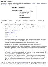
Insulated <strong>and</strong><br />
verticallyadjustableboatheater<br />
evaporator<br />
Rotat<strong>in</strong>g drum<br />
with mov<strong>in</strong>g<br />
nanofluid film<br />
Nitrogen<br />
cool<strong>in</strong>g plate with coils<br />
<strong>and</strong> f<strong>in</strong>s<br />
Fig. 1: Improved new-design for the one-step,<br />
direct-evaporation nanofluid production apparatus<br />
(U.S. Patent No. 7,718,033) [23]<br />
An improved “One-step method for the production of nanofluids” has been developed <strong>and</strong> a U.S.<br />
patent has been issued recently [23], see also Fig. 1. The improved method <strong>and</strong> system is provided for<br />
produc<strong>in</strong>g nanofluids by a so called one-step direct metal evaporation <strong>and</strong> its deposition on a mov<strong>in</strong>g<br />
liquid film <strong>and</strong> further dispersion <strong>and</strong> mix<strong>in</strong>g of nanoparticles with<strong>in</strong> the fluid.<br />
The improved method <strong>and</strong> system is achieved by the follow<strong>in</strong>g: better position<strong>in</strong>g (longitud<strong>in</strong>al<br />
<strong>in</strong>stead of crosswise) <strong>and</strong> variable-adjustable distance between the metal evaporation source <strong>and</strong> liquid<br />
film, which achieves smaller particle deposition path <strong>and</strong> smaller fluid-film exposure over the heated<br />
source <strong>and</strong> thus smaller nanoparticle size, but at the same time it provides larger liquid film area <strong>and</strong> thus<br />
larger deposition rate. Furthermore, better heater evaporation source <strong>in</strong>sulation reduces the heat<strong>in</strong>g power<br />
which is possible to be balanced by an improved new heat-exchanger design of nitrogen cooler <strong>and</strong><br />
<strong>in</strong>creased drum rotation, thus provid<strong>in</strong>g lower liquid temperature <strong>and</strong> pressure which contributes to<br />
smaller nanoparticle size, <strong>and</strong> provides for cont<strong>in</strong>uous, steady-state production of nanofluids with desired<br />
nanoparticle size distribution. Additional improvement features <strong>in</strong>clude a liquid feed-<strong>in</strong>, <strong>in</strong>ert gas<br />
flash<strong>in</strong>g, visual observation, <strong>and</strong> better process heat<strong>in</strong>g control all of which further contribute to<br />
cont<strong>in</strong>uous, steady-state operation <strong>and</strong> control of temperature <strong>and</strong> pressure for production <strong>and</strong><br />
optimization of desired nanofluid qualities <strong>and</strong> quantities.<br />
The improved one-step process <strong>and</strong> system for production of nanofluids <strong>in</strong>cludes plac<strong>in</strong>g a base fluid,<br />
such as ethylene glycol or oil, <strong>in</strong> a rotat<strong>in</strong>g cyl<strong>in</strong>drical drum situated <strong>in</strong> a vacuum chamber. The rotat<strong>in</strong>g<br />
axis of the drum is preferably horizontal, <strong>and</strong> the drum with solid back-endplate conta<strong>in</strong>s annular frontendplate<br />
to prevent the liquid from runn<strong>in</strong>g out but provid<strong>in</strong>g entrance for metal evaporator heater <strong>and</strong><br />
nitrogen cooler elements. An electric motor rotates the drum at a designated rotational speed. As the<br />
drum rotates, it drags liquid filled <strong>in</strong> the bottom part of the drum along its <strong>in</strong>side cyl<strong>in</strong>drical surface,<br />
form<strong>in</strong>g a th<strong>in</strong> film of liquid on the <strong>in</strong>ner surface above the pool of liquid <strong>in</strong> the bottom of the drum. An<br />
evaporation boat heater is positioned <strong>in</strong> close proximity to the upper <strong>in</strong>side surface of the cyl<strong>in</strong>drical<br />
drum. The metal evaporates at a given rate <strong>and</strong> the gaseous molecules rise outwards <strong>and</strong> condense onto<br />
the liquid film on the revolv<strong>in</strong>g drum. The liquid is cooled by <strong>in</strong>sert<strong>in</strong>g a metallic heat exchanger <strong>in</strong> the<br />
5
liquid <strong>and</strong> pass<strong>in</strong>g liquid nitrogen through the exchanger. In a steady-state process, the cool<strong>in</strong>g capacity<br />
of the heat exchanger balances the heat <strong>in</strong>put from the evaporator <strong>and</strong> heat ga<strong>in</strong>s from the surround<strong>in</strong>gs.<br />
In a most preferred form of the <strong>in</strong>vention, the method <strong>and</strong> system <strong>in</strong>cludes: (a) strategic position<strong>in</strong>g<br />
of the boat-heater that evaporates the metal close to the mov<strong>in</strong>g liquid film <strong>in</strong> the axial drum direction,<br />
<strong>in</strong>stead of perpendicular to the drum axis, <strong>and</strong> with adjustable spac<strong>in</strong>g of the evaporator relative to the<br />
liquid film; (b) a boat/heater that is thermally well <strong>in</strong>sulated with foam, foil <strong>and</strong> radiation shields; (c)<br />
better liquid cool<strong>in</strong>g by substantially <strong>in</strong>creas<strong>in</strong>g drum rotational speed, improv<strong>in</strong>g the design of the heat<br />
exchanger that cools the base liquid with liquid nitrogen flow, <strong>in</strong>clud<strong>in</strong>g optimized cooler-to-drum gap<br />
<strong>and</strong> f<strong>in</strong> spac<strong>in</strong>g, <strong>and</strong> addition of cool<strong>in</strong>g f<strong>in</strong>s to the rotat<strong>in</strong>g drum if needed; <strong>and</strong> (d) well controlled,<br />
adjustable evaporator temperature <strong>and</strong> balanced cool<strong>in</strong>g to provide for desired nanoparticle size<br />
distribution <strong>in</strong> a steady-state process, for controlled <strong>and</strong> cont<strong>in</strong>uous nanoparticle production.<br />
This improved process <strong>and</strong> system allows for much better process control with the result<strong>in</strong>g<br />
improvement <strong>in</strong> the quality <strong>and</strong> quantity of the nanofluids produced by the process. The system<br />
improvements, such as placement of the boat/heater evaporator closer to the top of the rotat<strong>in</strong>g drum,<br />
<strong>in</strong>creas<strong>in</strong>g the drum rotation speed, <strong>and</strong> use of f<strong>in</strong>s to <strong>in</strong>crease surface area for cool<strong>in</strong>g give rise to<br />
numerous advantages. These <strong>and</strong> other improvements are described <strong>in</strong> much greater detail elsewhere<br />
[23].<br />
3. NANOFLUIDS STABILITY AND INFLUENCE OF ADDITIVES:<br />
Friction-Drag Reduction <strong>and</strong> Issue of Heat-Transfer Reduction (Development of<br />
Polymer-<strong>Nanofluids</strong>)<br />
As already stated, the conglomeration <strong>and</strong> cluster<strong>in</strong>g of nanoparticles <strong>in</strong> the nanofluid mixture is<br />
tak<strong>in</strong>g place before <strong>and</strong> after the nanofluid is made <strong>and</strong> dur<strong>in</strong>g its use, <strong>and</strong> depends on many factors,<br />
especially on additives used. Two nanofluid samples with all of the parameters be<strong>in</strong>g the same but<br />
different type <strong>and</strong> amount of surfactants <strong>and</strong>/or pH adjusters used, may result <strong>in</strong> quite different thermophysical<br />
properties <strong>and</strong> flow <strong>and</strong> heat-transfer characteristics of apparently the same nanofluids. These<br />
<strong>and</strong> other unknown factors may expla<strong>in</strong> anomalous <strong>and</strong> controversial results obta<strong>in</strong>ed by different<br />
researches.<br />
The particle size distribution of nanoparticles is another important factor <strong>and</strong> report<strong>in</strong>g the average<br />
particle size is not sufficient to characterize a nanofluid. It is also known that cyl<strong>in</strong>drical <strong>and</strong> rod-shaped<br />
particles offer higher thermal enhancement when compared to spherical particles. More consistent<br />
research should be made for the <strong>in</strong>vestigation of the properties <strong>and</strong> thermal performance of wellcharacterized<br />
‘static’ <strong>and</strong> dynamic constitution of nanofluids, s<strong>in</strong>ce there are more hypothetical theories<br />
proposed than reliable results to verify those theoretical models.<br />
In addition to <strong>in</strong>vestigat<strong>in</strong>g the effects of basic parameters such as particle size, base fluid, <strong>and</strong><br />
particle volume fraction, the researchers should well control <strong>and</strong> report all important parameters,<br />
<strong>in</strong>clud<strong>in</strong>g additives used, details of ultrasonic treatment, <strong>and</strong> others. No wonder that effects of many<br />
parameters on the thermal conductivity <strong>and</strong> viscosity of nanofluids has not been fully understood yet,<br />
which are important prerequisites for better underst<strong>and</strong><strong>in</strong>g, development <strong>and</strong> optimization of nanofluid<br />
flow <strong>and</strong> thermal performance.<br />
Another important, but overlooked issue with use of additives <strong>in</strong> nanofluids is a possibility to<br />
drastically reduce friction drug <strong>in</strong> turbulent flow (desired effect; used <strong>in</strong> Trans-Alaska oil pipel<strong>in</strong>e<br />
system), which is usually accompanied with commensurate heat-transfer reduction, the letter be<strong>in</strong>g an<br />
undesirable, adverse effect. These drag <strong>and</strong> heat-transfer reduction phenomena, described next, are wellknown<br />
by some researchers but are not widely known <strong>and</strong> thus overlooked by nanofluid researchers.<br />
6
3.1. Friction-drag reduction <strong>and</strong> issue of heat-transfer reduction -- development of polymernanofluids:<br />
A class of fluids, known as “drag-reduction” fluids, has <strong>in</strong>trigued many <strong>in</strong>vestigators, ever s<strong>in</strong>ce<br />
Toms’ discovery [24] that the friction drag of common fluids with m<strong>in</strong>ute concentrations of certa<strong>in</strong><br />
polymer additives, under turbulent flow conditions, is considerably smaller (several times) than the<br />
expected values. Drag-reduction fluids are also nanofluids, i.e. solutions of m<strong>in</strong>ute concentrations of<br />
certa<strong>in</strong> nano-size (sometimes micro-size) additives, like high-polymers, soap <strong>and</strong> surfactant aggregates, or<br />
fibers, <strong>in</strong> common fluids, like water or oil. The pressure drop <strong>and</strong> heat-transfer <strong>in</strong> turbulent pipe with<br />
drag-reduc<strong>in</strong>g fluids (classified as non-Newtonian fluids if with higher concentration of additives) is<br />
several times lower than for the correspond<strong>in</strong>g Newtonian fluids as discussed <strong>in</strong> an extensive review by<br />
Metzner [25]. These phenomena can be characterized by the so-called Virk’s m<strong>in</strong>imum asymptotic<br />
friction value [26]. Unfortunately, heat-transfer is also reduced. Hartnett <strong>and</strong> <strong>Kostic</strong> [27] have studded<br />
the drag-reduc<strong>in</strong>g fluids <strong>in</strong> lam<strong>in</strong>ar non-circular duct flows <strong>and</strong> discovered enhanced heat transfer. They<br />
reviewed the flow <strong>and</strong> heat transfer phenomena of Newtonian <strong>and</strong> non-Newtonian fluids <strong>in</strong> rectangular<br />
ducts [27], <strong>and</strong> <strong>Kostic</strong> [28] presented an overview on turbulent drag <strong>and</strong> heat transfer reduction <strong>and</strong><br />
lam<strong>in</strong>ar heat transfer enhancement of certa<strong>in</strong> non-Newtonian fluids <strong>in</strong> non-circular duct flows.<br />
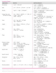
RANDOMLY<br />
ORIENTED<br />
MACRO-<br />
MOLECULES<br />
MOTIONLESS<br />
FLUID<br />
Fig. 2: Shear-rate dependent viscosity due to process-adjust<strong>in</strong>g active<br />
structure of an aqueous polymer solution [28]<br />
Complex fluids, like polymer solutions have functional, process-adjust<strong>in</strong>g, active molecularstructures,<br />
<strong>and</strong> exhibit well-known shear-rate dependent viscosity, see Fig. 2. R<strong>and</strong>omly-oriented, longcha<strong>in</strong><br />
macro-molecules <strong>in</strong>crease substantially the zero-shear-rate (zero velocity) solution viscosity, but<br />
under shear<strong>in</strong>g stresses, they self-align with the flow <strong>and</strong> viscosity is substantially reduced with the shearrate<br />
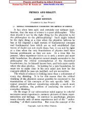
<strong>in</strong>crease. This is more dramatically demonstrated <strong>in</strong> turbulent flow, where a m<strong>in</strong>ute concentration (50<br />
ppm) of long-cha<strong>in</strong> macromolecules may reduce turbulent friction fivefold by suppress<strong>in</strong>g transverse<br />
turbulence fluctuations, <strong>and</strong> <strong>in</strong> turn substantially reduce turbulence dissipation <strong>and</strong> over-all friction, see<br />
Fig. 3 [28]. Regrettably, the turbulent heat transfer is commensurately reduced. Similarly, the<br />
nanoparticles could re-align <strong>and</strong> process-adjust dur<strong>in</strong>g flow <strong>and</strong> heat-transfer processes. There is a need to<br />
selectively choose or develop new nanoparticles <strong>and</strong> drag-reduction additives to optimize flow <strong>and</strong> heat<br />
transfer characteristics of hybrid nanoparticle+additive based nanofluids.<br />
7<br />
FLOW-INDUCED<br />
ANISOTROPICITY<br />
FLOW-ORIENTED<br />
MACRO-<br />
MOLECULES
Fig. 3: Friction-factor vs. Reynolds-number curves for lam<strong>in</strong>ar, turbulent,<br />
<strong>and</strong> polymer drag-reduc<strong>in</strong>g asymptotic flows<br />
(<strong>in</strong> semi-log scale as opposed to usual log-log scale) [28].<br />
The polymer-nanofluids, could be developed, <strong>and</strong> are expected to be even more complex <strong>and</strong> active<br />
fluid mixtures, <strong>and</strong> thus have more degrees-of-freedom to ‘self-adjust’ under different process- <strong>and</strong>/or<br />
field-conditions. To develop, study, underst<strong>and</strong>, <strong>and</strong> optimize polymer-nanofluid functionalities, by<br />
reduc<strong>in</strong>g <strong>in</strong>stabilities while promot<strong>in</strong>g those fluid structural activities that enhance flow <strong>and</strong> heat transfer<br />
characteristics as well as other characteristics, will be a research challenge <strong>and</strong> potential for many<br />
applications.<br />
Another research challenge could be to comb<strong>in</strong>e the selected nanoparticles <strong>and</strong> drag-reduc<strong>in</strong>g<br />
additives, <strong>and</strong> thus develop <strong>and</strong> optimize a Drag-Reduc<strong>in</strong>g nanofluid (dubbed here DR-nanofluid). The<br />
expectation is to obta<strong>in</strong> a hybrid nanofluid with improved flow <strong>and</strong> heat transfer characteristics. The dragreduc<strong>in</strong>g<br />
fluids may conta<strong>in</strong> water, different co-solvents, lubricants, co-polymer emulsions, dispersants<br />
<strong>and</strong> surfactants, rheological agents, surface energy controlled agents, <strong>and</strong> pH <strong>and</strong> ionic strength adjust<strong>in</strong>g<br />
agents. The formulation pr<strong>in</strong>ciple <strong>and</strong> techniques for drag-reduc<strong>in</strong>g fluids <strong>and</strong> nanofluids should be<br />
8
similar to those formulations of water-based organic-<strong>in</strong>organic hybrid emulsions. Different techniques<br />
could be developed <strong>and</strong> employed to synthesize <strong>and</strong> formulate the nanofluids with polymer additives.<br />
Furthermore, develop<strong>in</strong>g nanofluids with polymer additives or “POLY-nanofluids” may have other<br />
applications, beyond the advanced heat-transfer fluids, for creat<strong>in</strong>g more functional nanostructures, s<strong>in</strong>ce<br />
polymer molecules may provide an enhanced web-like structure for nanoparticles <strong>in</strong> base fluids.<br />
Development of nanofluids, with enhanced or entirely different properties from their base fluids, is a new<br />
challenge <strong>and</strong> opportunity, <strong>and</strong> may have unprecedented application potentials, not only <strong>in</strong> thermal<br />
management <strong>and</strong> efficient cool<strong>in</strong>g, but also <strong>in</strong> <strong>in</strong>dustry, build<strong>in</strong>gs, environmental <strong>and</strong> bio-medical<br />
applications, as well as emerg<strong>in</strong>g critical applications.<br />
4. THERMAL CONDUCTIVITY MEASUREMENTS: Possible <strong>Issues</strong> with <strong>Nanofluids</strong><br />
Thermal conductivity measurements of suspensions of nanoparticles <strong>in</strong> common, base fluids<br />
conducted <strong>in</strong> Argonne national Laboratory almost two decade ago, discovered “anomalous” enhancement<br />
of thermal conductivity, compared to the suspensions of the same type <strong>and</strong> concentration but larger-size<br />
particles, <strong>and</strong> as “expected” values, predicted with the heterogeneous mixture theory. The “nanofluid”<br />
name was <strong>in</strong>troduced to represent such suspension of nano-particles <strong>in</strong> a common fluid. Exceptional<br />
enhancement of nanofluids thermal conductivity <strong>and</strong> potential for development of substantially improved<br />
heat transfer fluids, have propelled research <strong>and</strong> publications, almost exponentially. A number of review<br />
articles have been published [1-6], <strong>and</strong> more recent extensive experimental <strong>in</strong>vestigation [29].<br />
Most of the measured results, reviewed <strong>in</strong> the above references, show significant enhancement of<br />
nanofluids thermal conductivity (TC), but some with large discrepancy <strong>in</strong> the values, while some others<br />
without significant enhancement over predictions of classical mixture theory [30]. Usually, three<br />
measurement methods have been used: steady-state method; transient oscillation method, <strong>and</strong> <strong>in</strong> most<br />
cases the transient Hot-Wire Thermal Conductivity (HWTC) method. In addition to the enhancement of<br />
nanofluids TC with nanoparticle concentration, a strong dependence of TC on temperature is observed.<br />
S<strong>in</strong>ce the measured nanofluids TC enhancement has not been understood <strong>and</strong> justified yet, there is a need<br />
to <strong>in</strong>vestigate <strong>in</strong>fluence of measurement methods on the obta<strong>in</strong>ed results, s<strong>in</strong>ce all apparatus calibration<br />
have been performed with classical fluids with known TC. However, there may be some unknown issues<br />
with measurements of complex <strong>and</strong> dynamic (usually unstable) nanofluid structures. For example,<br />
<strong>in</strong>fluence of electromagnetic fields on nano-particle fluid molecule <strong>in</strong>teractions, possible nano-convection<br />
effects related to measurement methods, or <strong>in</strong>fluence of temperature gradients on TC results.<br />
Therefore, <strong>in</strong> this section, only a couple of selected issues will be covered, namely, a proposed<br />
improvement of a Hot-Wire Thermal Conductivity (HWTC) apparatus, <strong>and</strong> a design <strong>and</strong> comparative<br />
measurement us<strong>in</strong>g steady-state Parallel-Plate Thermal Conductivity (PPTC) apparatus. Both are<br />
described <strong>in</strong> details to facilitate their replication <strong>and</strong> possible future improvements.<br />
A new <strong>and</strong> improved HWTC apparatus for thermal conductivity measurements of common fluids <strong>and</strong><br />
nanofluids has been recently developed, designed <strong>and</strong> fabricated [31, 32]. A plat<strong>in</strong>um (Pt) wire of 50.8 µm<br />
diameter with a Teflon <strong>in</strong>sulation coat<strong>in</strong>g of 25.4 µm thickness was used as the hot-wire heater <strong>and</strong><br />
temperature sensor for the present application. The new apparatus employs <strong>in</strong>novative solutions for easy<br />
calibration of uniform Pt-wire tension <strong>and</strong> thus m<strong>in</strong>imiz<strong>in</strong>g the stra<strong>in</strong> <strong>in</strong>fluence on temperature<br />
measurement (i.e., m<strong>in</strong>imiz<strong>in</strong>g the well-known <strong>and</strong> unwanted “stra<strong>in</strong>-gage effect” on Pt-wire electrical<br />
resistivity); measurement of Pt-wire voltage drop <strong>in</strong>dependently from power wir<strong>in</strong>g (four wires); <strong>and</strong> an<br />
effective off-centered mechanical design to m<strong>in</strong>imize the test fluid sample size (about 35 mL), but at the<br />
same time provid<strong>in</strong>g additional space for wir<strong>in</strong>g, <strong>in</strong>clud<strong>in</strong>g three <strong>in</strong>side thermocouples for fluid<br />
temperature uniformity verification. Data acquisition hardware <strong>and</strong> LabVIEW® application software are<br />
optimized to m<strong>in</strong>imize signal noise <strong>and</strong> enhance acquisition <strong>and</strong> process<strong>in</strong>g of useful data.<br />
9
In addition, a steady-state, parallel-plate thermal conductivity (PPTC) apparatus has been developed<br />
<strong>and</strong> used for comparative measurements of complex POLY-nanofluids [33, 34], <strong>in</strong> order to compare<br />
results with the correspond<strong>in</strong>g measurements us<strong>in</strong>g the transient, hot-wire thermal conductivity (HWTC)<br />
apparatus. The related measurements <strong>in</strong> the literature, mostly with HWTC method, have been <strong>in</strong>consistent<br />
<strong>and</strong> with measured thermal conductivities far beyond prediction us<strong>in</strong>g the well-known mixture theory<br />
[30]. The objective was to check out if exist<strong>in</strong>g <strong>and</strong> well-established HWTC method might have some<br />
unknown issues while measur<strong>in</strong>g TC of complex nano-mixture suspensions, like electro-magnetic<br />
phenomena, undetectable hot-wire vibrations, <strong>and</strong> others.<br />
These <strong>in</strong>itial <strong>and</strong> limited measurements have shown considerable difference between the two<br />
methods, where the TC enhancements measured with PPTC apparatus were about three times smaller than<br />
with HWTC apparatus, the former data be<strong>in</strong>g much closer to the mixture theory prediction. However, the<br />
<strong>in</strong>fluence of measurement method is not conclusive s<strong>in</strong>ce it has been observed that the complex nanomixture<br />
suspensions were very unstable dur<strong>in</strong>g the lengthy steady-state measurements as compared to<br />
rather quick transient HWTC method. The nanofluid suspension <strong>in</strong>stability might be the ma<strong>in</strong> reason for<br />
very <strong>in</strong>consistent results <strong>in</strong> the literature. It is necessary to expend <strong>in</strong>vestigation with more stable nanomixture<br />
suspensions.<br />
4.1. Improved, Transient Hot-Wire Thermal Conductivity (HWTC) Apparatus for <strong>Nanofluids</strong>:<br />
A new <strong>and</strong> improved, transient hot-wire thermal conductivity apparatus has been developed to<br />
measure the thermal conductivity of fluids, polymer solution, nanofluids <strong>and</strong> poly-nanofluids (a mixture<br />
of nano particles, polymers <strong>and</strong> conventional heat transfer fluids) [31, 32]. The apparatus is a part of a<br />
research program at Northern Ill<strong>in</strong>ois University with an objective to resolve some critical issues <strong>in</strong><br />
nanofluids research <strong>and</strong> to develop <strong>and</strong> optimize new hybrid, drag-reduc<strong>in</strong>g polymer-nanofluids with<br />
enhanced thermo-physical characteristics [36, 37]. Thermal conductivity, a measure of material’s ability<br />
to conduct heat, is a very important property for thermal analysis.<br />
The mathematical model for the hot-wire method is based on an ideal, <strong>in</strong>f<strong>in</strong>itely long <strong>and</strong> th<strong>in</strong><br />
cont<strong>in</strong>uous l<strong>in</strong>e source dissipat<strong>in</strong>g heat, of heat flux q per unit length, applied at time t = 0, <strong>in</strong> an <strong>in</strong>f<strong>in</strong>ite<br />
<strong>and</strong> <strong>in</strong>compressible medium. The general assumption is that heat transfer to the <strong>in</strong>f<strong>in</strong>ite medium, of<br />
thermal conductivity k f <strong>and</strong> thermal diffusivity f k f f C f , is by conduction alone <strong>and</strong> thus<br />
<strong>in</strong>creases the both temperatures <strong>in</strong> time, of the heat-source <strong>and</strong> test-medium. It is also assumed that the<br />
l<strong>in</strong>e heat-source has uniform <strong>in</strong>stant temperature everywhere, but transient <strong>in</strong> time (virtually achieved<br />
with small diameter <strong>and</strong> long wire with large thermal conductivity <strong>and</strong>/or small heat capacity). The<br />
govern<strong>in</strong>g equation is derived from the Fourier’s equation for one-dimensional (1-D) transient heat<br />
conduction <strong>in</strong> cyl<strong>in</strong>drical coord<strong>in</strong>ates,<br />
1 T<br />
1 T<br />
<br />
r<br />
<br />
t<br />
r r<br />
r<br />
<br />
f<br />
Where, T T0 T<br />
is the temperature of the medium at any time, t <strong>and</strong> arbitrary radial distance, r ; T 0 is<br />
the <strong>in</strong>itial temperature of the source <strong>and</strong> medium, <strong>and</strong> T is the temperature difference between the<br />
medium <strong>and</strong> <strong>in</strong>itial temperature. The Eq. (1) is the subject of the follow<strong>in</strong>g boundary conditions:<br />
T<br />
<br />
<br />
<br />
q<br />
limr <br />
r0 r<br />
2k<br />
f<br />
Tr, t<br />
0<br />
lim <br />
r<br />
at t 0 <strong>and</strong> r 0 , (2)<br />
at t 0 <strong>and</strong> r , (3)<br />
Where, f<br />
<strong>and</strong> f<br />
C are density <strong>and</strong> specific heat capacity of the test medium, respectively. The <strong>in</strong>f<strong>in</strong>ite<br />
series solution of this problem is outl<strong>in</strong>ed by Carslaw <strong>and</strong> Jaeger [38]. After <strong>in</strong>itial, short transient period<br />
10<br />
(1)
2 (i.e., t r 4<br />
; note, this transiency is much longer for f<strong>in</strong>ite wire diameter, <strong>in</strong>clud<strong>in</strong>g <strong>in</strong>solation if<br />
f<br />
any), except for the first term conta<strong>in</strong><strong>in</strong>g time t, the higher order terms could be neglected, result<strong>in</strong>g <strong>in</strong> a<br />
very good approximation as,<br />
where =0.5772 is the Euler’s constant.<br />
q <br />
4<br />
f t <br />
T T ( r,<br />
t)<br />
T <br />
<br />
0 ln<br />
2 <br />
4k<br />
f r <br />
For constant fluid medium properties <strong>and</strong> a fixed <strong>and</strong> arbitrary radius r, after differentiation of Eq.<br />
(4), the radius is elim<strong>in</strong>ated from the equation, <strong>and</strong> the follow<strong>in</strong>g relation is obta<strong>in</strong>ed,<br />
q 1<br />
k f <br />
(5)<br />
4 dT<br />
/ d ln( t)<br />
Therefore, if temperature of the medium is measured as function of time at any fixed radial position,<br />
<strong>in</strong>clud<strong>in</strong>g at the contact with the l<strong>in</strong>e source (i.e. the temperature of the ‘th<strong>in</strong>’ l<strong>in</strong>e source), the thermal<br />
conductivity of the test medium, k f , is proportional to the source heat flux <strong>and</strong> <strong>in</strong>versely proportional to<br />
the temperature (or temperature difference) gradient with regard to the natural logarithm of time, see Eq.<br />
(5).<br />
The advantage of the hot-wire method is its simplicity <strong>and</strong> consequently low cost of construction.<br />
Furthermore, the wire itself acts as both the heat<strong>in</strong>g source <strong>and</strong> temperature sensor for measurement.<br />
Another advantage is that convection heat transfer effects can be m<strong>in</strong>imized <strong>and</strong> identified when present<br />
as deviation of the l<strong>in</strong>earity <strong>in</strong> the plot of T as a function of ln(t).<br />
4.1.1. <strong>Application</strong> of Hot-Wire Method for <strong>Nanofluids</strong>:<br />
A bare metal wire centered <strong>in</strong> a fluid medium is generally used for thermal conductivity measurement<br />
of fluids by the transient hot-wire method. <strong>Nanofluids</strong> conta<strong>in</strong><strong>in</strong>g metal particles are electrically<br />
conductive, so application of a bare wire could lead to ambiguous results <strong>in</strong> the measurements. Some of<br />
the problems identified by Nagasaka <strong>and</strong> Nagashima [39] <strong>in</strong> the application of the ord<strong>in</strong>ary transient hotwire<br />
method to electrically conduct<strong>in</strong>g liquids are: (a) possible current flow through the liquid, result<strong>in</strong>g<br />
<strong>in</strong> ambiguous measurement of heat generated <strong>in</strong> the wire; (b) polarization of the wire surface;<br />
(c) distortion of output voltage signal due to <strong>in</strong>fluence of the conduct<strong>in</strong>g liquid cell.<br />
In order to overcome these errors, it is recommended that the bare metal wire should be coated us<strong>in</strong>g<br />
electrically <strong>in</strong>sulat<strong>in</strong>g material. The effect on temperature distribution due to th<strong>in</strong> <strong>in</strong>sulation coat<strong>in</strong>g has<br />
been analyzed [39] <strong>and</strong> outl<strong>in</strong>ed by Yamasue et al. [40]. The temperature rise T of the hot-wire is given<br />
as,<br />
q 1<br />
T lnt<br />
Ao<br />
ln<br />
4k<br />
t<br />
11<br />
<br />
BotC o<br />
f<br />
The terms A o , B o <strong>and</strong> C o are def<strong>in</strong>ed as follows:<br />
4<br />
f 2k<br />
f r k<br />
ln <br />
o f<br />
Ao<br />
<br />
<br />
ln ...<br />
2 <br />
ro<br />
ki<br />
rw<br />
2kw<br />
(4)<br />
(6)<br />
(7)<br />
1 <br />
k <br />
2 ki<br />
kw<br />
2 f<br />
<br />
<br />
ki<br />
B <br />
<br />
<br />
<br />
<br />
<br />
o rw<br />
ro<br />
(8)<br />
2k<br />
<br />
<br />
f i w f i
C<br />
o<br />
2<br />
rw<br />
<br />
k f ki<br />
<br />
1 1 4 2 <br />
<br />
<br />
<br />
8 k <br />
<br />
<br />
<br />
<br />
<br />
w <br />
w i i w <br />
2<br />
r <br />
o 1<br />
<br />
2 <br />
f<br />
2<br />
1 rw<br />
ki<br />
kw<br />
ro<br />
<br />
<br />
ln<br />
i k <br />
<br />
i i <br />
<br />
<br />
<br />
w r <br />
<br />
<br />
w <br />
1<br />
<br />
2k<br />
f<br />
<br />
k<br />
2 ki<br />
k <br />
w 2 f<br />
rw<br />
r <br />
<br />
<br />
o<br />
<br />
i <br />
<br />
<br />
w f<br />
k 4<br />
i <br />
f<br />
ln<br />
2 <br />
i <br />
ro<br />
<br />
where, r w is the radius of the wire; <strong>and</strong> r o is the sum of the radius of the wire r w <strong>and</strong> the <strong>in</strong>sulation<br />
thickness i . Subscripts w, I, <strong>and</strong> f represent wire, <strong>in</strong>sulation coat<strong>in</strong>g, <strong>and</strong> liquid, respectively.<br />
Comparison of Eq. (4) <strong>and</strong> (6) <strong>in</strong>dicates that the term 1 tB o lnt<br />
Co<br />
is due to the presence of the<br />
<strong>in</strong>sulation layer on the wire. If the term 1 tB lnt<br />
C is negligibly small compared to the ln t A <br />
o<br />
term, then the constant A o shifts (i.e., offsets) the plot of T aga<strong>in</strong>st ln(t), without chang<strong>in</strong>g the slope.<br />
Therefore, the thermal conductivity, k f , is aga<strong>in</strong> accurately determ<strong>in</strong>ed us<strong>in</strong>g Eq. (5). Yu <strong>and</strong> Choi have<br />
analyzed the wire temperature rise as a function of time, to determ<strong>in</strong>e the <strong>in</strong>fluence of <strong>in</strong>sulation coat<strong>in</strong>g<br />
on the thermal conductivity measurement <strong>and</strong> have concluded that relative measurement error of thermal<br />
conductivity is negligible if the slope of T aga<strong>in</strong>st ln(t) is measured at later times after start of heat<strong>in</strong>g,<br />
<strong>and</strong> that no correction to <strong>in</strong>sulation coat<strong>in</strong>g is necessary, even if the <strong>in</strong>sulation coat<strong>in</strong>g thickness is<br />
comparable to the wire radius.<br />
Electrical <strong>in</strong>sulation coat<strong>in</strong>g to bare metal wire has been recommended for electrically conduct<strong>in</strong>g<br />
fluids. Nagasaka <strong>and</strong> Nagashima [39] have coated the plat<strong>in</strong>um wire (diameter 40 µm) with polyester<br />
<strong>in</strong>sulation (thickness 7.5 µm) to measure electrically conduct<strong>in</strong>g aqueous NaCl solution. Whereas, Perk<strong>in</strong>s<br />
[41] anodized a tantalum wire (diameter 25.4 µm) to form an electrically <strong>in</strong>sulat<strong>in</strong>g layer of tantalum<br />
peroxide (thickness 70 nm), Yu et al. [42] have applied an epoxy <strong>in</strong>sulation coat<strong>in</strong>g (estimated thickness<br />
10 µm) to a plat<strong>in</strong>um wire (diameter 76.2 µm) to measure thermal conductivity of nanofluids. Jwo et al.<br />
[43] <strong>in</strong>sulated a Nickel-Chromium alloy wire with Teflon to measure thermal conductivity of CuO<br />
nanofluids. More recently, Ma [44] <strong>in</strong> his thesis has utilized a plat<strong>in</strong>um wire (diameter 25 µm) with an<br />
Isonel <strong>in</strong>sulation coat<strong>in</strong>g (thickness 1.5 µm) to measure thermal conductivity of various comb<strong>in</strong>ations of<br />
nano crystall<strong>in</strong>e material <strong>and</strong> base fluids.<br />
4.1.2. Hot-Wire Cell Design:<br />
The ma<strong>in</strong> design parameters are: (a) material of hot-wire, (b) radius of hot-wire, (c) <strong>in</strong>sulation<br />
coat<strong>in</strong>g, (d) length of hot-wire, (e) radius of the test sample outer boundary, <strong>and</strong> (f) length of the sample.<br />
Plat<strong>in</strong>um has been selected as superior hot wire material. It has higher thermal conductivity (TC)<br />
compared to the nichrome <strong>and</strong> tantalum, also used as hot-wires. Along with the material, hot-wire radius<br />
is one of the most important parameters for the cell design. Among commercially available sizes, 25.4 <strong>and</strong><br />
50.8 µm radius plat<strong>in</strong>um-wires have been selected for the present application, s<strong>in</strong>ce smaller 12.5 µm radii<br />
is considered to be too fragile for clean<strong>in</strong>g <strong>and</strong> h<strong>and</strong>l<strong>in</strong>g of nanofluid samples.<br />
Teflon has been selected as <strong>in</strong>sulat<strong>in</strong>g material, as it is highly resistant to chemical reactions,<br />
corrosion <strong>and</strong> stress-crack<strong>in</strong>g at high temperatures. A 50.8 µm diameter plat<strong>in</strong>um wire with a Teflon<br />
<strong>in</strong>sulation coat<strong>in</strong>g of 25.4 µm thickness, manufactured by A-M Systems, Inc., has been used as the hotwire.<br />
Care has been taken to avoid any disruption of the coat<strong>in</strong>g dur<strong>in</strong>g hot-wire mount<strong>in</strong>g.<br />
In our design [32], the length of the plat<strong>in</strong>um hot-wire was taken as w<br />
L = 0.1484 m, based on the<br />
0.139 m m<strong>in</strong>imum length of hot-wire, determ<strong>in</strong>ed accord<strong>in</strong>g to Kierkus et al. [45] criteria, for our<br />
application data. Based on Healy et al. [46] criteria, the m<strong>in</strong>imum hot-wire cell outer boundary radius was<br />
12<br />
o<br />
(9)<br />
o
determ<strong>in</strong>ed as 0.0028 m, but chosen to be R c = 0.00718 m, <strong>and</strong> the f<strong>in</strong>ite length of the sample to be<br />
L c = 0.170 m. The overall sample volume V c after fabrication is calibrated to be 35 ml.<br />
Measurement Section<br />
149.2 mm<br />
Spr<strong>in</strong>g Rod with Extenal Threads<br />
Calibration Gauge<br />
Lock<strong>in</strong>g Nut<br />
(calibrated weight for required<br />
(to guard spr<strong>in</strong>g rod <strong>and</strong><br />
calibrate the spr<strong>in</strong>g tension)<br />
spr<strong>in</strong>g tension) To the Data Acquisition System<br />
Power Supply Connector<br />
Connectors <strong>and</strong><br />
Calibration Gauge Holder<br />
Special Shape Slid<strong>in</strong>g Fit Hole<br />
(avoids turn<strong>in</strong>g of spr<strong>in</strong>g)<br />
Cell Cap with Rectangular Cuts<br />
(for wire outlet)<br />
Tension Spr<strong>in</strong>g<br />
(spr<strong>in</strong>g constant 0.0166 N/mm)<br />
Constant Voltage Input Wires<br />
Slid<strong>in</strong>g Tube<br />
(aligns the hot-wire)<br />
Soldered Jo<strong>in</strong>t # 1<br />
Teflon Coated Plat<strong>in</strong>um Hot-Wire<br />
Ø 0.0508 mm<br />
Coat<strong>in</strong>g Thickness 0.0245 mm<br />
Soldered Jo<strong>in</strong>t # 2<br />
Off-Centered Alignment R<strong>in</strong>g<br />
Cell Base Plate<br />
Teflon Seal<strong>in</strong>g<br />
A cross sectional view of the newly designed hot-wire thermal conductivity apparatus with major<br />
mechanical components is shown <strong>in</strong> Fig. 4. The major assembly components of the apparatus’ cell are:<br />
base plate, outer shell, <strong>and</strong> cell cap with hot-wire. The cell base plate with a threaded hole at the center of<br />
the plate (sealed by a Teflon washer) is used for convenient assembl<strong>in</strong>g <strong>and</strong> disassembl<strong>in</strong>g the outer shell.<br />
The outer shell with 17.4 mm <strong>in</strong>ner diameter acts as the sample test fluid reservoir. The cell cap, designed<br />
to slide-fit <strong>in</strong>to the outer shell, is hollow <strong>in</strong>side. The <strong>in</strong>ner semi-circular hot-wire holder with an alignment<br />
r<strong>in</strong>g is soldered at the lower end at an offset. A hot-wire guid<strong>in</strong>g block, slid<strong>in</strong>g tube, tension spr<strong>in</strong>g, <strong>and</strong><br />
spr<strong>in</strong>g rod are all aligned at an offset <strong>in</strong>side the cap. The Teflon-coated plat<strong>in</strong>um wire is <strong>in</strong>directly<br />
connected to the tension spr<strong>in</strong>g via copper wires <strong>and</strong> a slid<strong>in</strong>g rod, which are aligned with the spr<strong>in</strong>g<br />
mechanism (i.e., slid<strong>in</strong>g tube, tension spr<strong>in</strong>g, spr<strong>in</strong>g rod <strong>and</strong> lock<strong>in</strong>g nut). A lock<strong>in</strong>g nut, fastened to the<br />
spr<strong>in</strong>g rod, is mounted on the top of the cap. Two symmetric rectangular cuts <strong>in</strong> the cap provide an<br />
open<strong>in</strong>g for rout<strong>in</strong>g of electrical <strong>and</strong> thermocouple wires. A connector <strong>and</strong> calibration gauge holder <strong>and</strong> a<br />
wire holder, made of Teflon, are mounted on the top <strong>and</strong> middle section of the cell cap.<br />
13<br />
D-Type Connector<br />
Hot-Wire Voltage Output Wires<br />
T-Type Thermocouples<br />
Wire Holder<br />
Striped Str<strong>and</strong>ed Copper Wire<br />
(to provide flexiblity <strong>and</strong> avoid backlash)<br />
Hot-Wire Guid<strong>in</strong>g Block<br />
(off-centered)<br />
Inner Wire Guide<br />
Wire Protection Clip # 1<br />
Outer Shell<br />
(test-fluid reservoir)<br />
Inner Semi-Circular<br />
Hot-Wire Holder<br />
Wire Protection Clip # 2<br />
Threaded Nut<br />
Thermocouple at the Bottom<br />
L45°<br />
Wire Protection Clip # 3<br />
Insulated Copper Wire<br />
Ø 0.254 mm<br />
Threaded Hole <strong>in</strong> Base Plate<br />
(assembly <strong>and</strong> clean<strong>in</strong>g)<br />
Fig. 4: Cross-sectional view of transient<br />
hot-wire thermal conductivity apparatus
Fig. 5: Fabricated transient hot-wire<br />
thermal conductivity apparatus<br />
Three thermocouples, mounted on the outer radius of <strong>in</strong>ner semi-circular hot-wire holder at 15º, 45º<br />
<strong>and</strong> 75º angles, along the length of the sample test section, monitor uniformity of the test fluid<br />
temperature. The thermocouple tip is bent towards the plat<strong>in</strong>um hot-wire through the holes on the <strong>in</strong>ner<br />
semi-circular hot-wire holder.<br />
Two copper wires at the top soldered-jo<strong>in</strong>t of the plat<strong>in</strong>um hot-wire are passed symmetrically through<br />
a slid<strong>in</strong>g tube. The <strong>in</strong>ner hollow portion of the slid<strong>in</strong>g tube is filled with epoxy to couple the copper wires<br />
with the slid<strong>in</strong>g tube. A clearance between the slid<strong>in</strong>g tube <strong>and</strong> hot-wire guid<strong>in</strong>g block hole ensure nearfrictionless<br />
motion of the slid<strong>in</strong>g tube. The spr<strong>in</strong>g rod is specially shaped to have external threads. A<br />
lock<strong>in</strong>g nut <strong>and</strong> spr<strong>in</strong>g rod are screwed together like a nut <strong>and</strong> bolt. The special shaped slid<strong>in</strong>g fit hole<br />
avoids turn<strong>in</strong>g of the spr<strong>in</strong>g rod when the lock<strong>in</strong>g nut is turned for adjust<strong>in</strong>g the tension of the hot-wire.<br />
The lock<strong>in</strong>g nut has been fabricated to a specific weight that is used for calibration of the plat<strong>in</strong>um hotwire<br />
tension, with<strong>in</strong> 50% of its ultimate tensile strength. An <strong>in</strong>verted L-shaped gauge has been seated on<br />
the holder for calibrat<strong>in</strong>g the hot-wire tension <strong>and</strong> guard<strong>in</strong>g the spr<strong>in</strong>g rod movement. One of the two<br />
copper wires at another soldered jo<strong>in</strong>t of the plat<strong>in</strong>um hot-wire is passed through the off-centered hole of<br />
the alignment r<strong>in</strong>g, while the other has been guided through a hole <strong>in</strong> the <strong>in</strong>ner semi-circular hot-wire<br />
holder. The copper wires at the alignment r<strong>in</strong>g act as fixed rigid ends of the hot-wire.<br />
The present cell parameters are Lc= 0.170 m, 2Rc = 0.01437 m, Vc = 35 ml, Lc/2Rc = 11.83. The<br />
parameters of the plat<strong>in</strong>um hot-wire with Teflon coat<strong>in</strong>g of thickness 25.4 µm are Lw = 0.1484 m,<br />
2rw = 50.8 µm, Lw/2rw = 2921, 2Rc/2rw = 282.9, <strong>and</strong> Lw/2Rc = 10.33.<br />
The controlled tightness of the th<strong>in</strong> plat<strong>in</strong>um hot-wire is a very important aspect. An <strong>in</strong>novative<br />
solution, to <strong>in</strong>directly connect a tension spr<strong>in</strong>g to the plat<strong>in</strong>um hot-wire, while ma<strong>in</strong>ta<strong>in</strong><strong>in</strong>g constant<br />
tension, has been <strong>in</strong>corporated. Also, a unique solution to calibrate the plat<strong>in</strong>um hot-wire tension has been<br />
developed. This arrangement m<strong>in</strong>imizes the well known <strong>and</strong> unwanted stra<strong>in</strong> gage effect on hot-wire<br />
electrical resistivity, thus decreas<strong>in</strong>g the stra<strong>in</strong> <strong>in</strong>fluence on temperature measurement. An extension<br />
spr<strong>in</strong>g with a low spr<strong>in</strong>g constant is calibrated <strong>and</strong> used for present application as detailed elsewhere [31].<br />
14
4.1.3. Instrumentation <strong>and</strong> Data Acquisition:<br />
A Wheatstone bridge circuit has been employed to measure the resistance change of the hot-wire,<br />
with the wire be<strong>in</strong>g one of the arms (i.e., resistors) of the bridge. Initially, the bridge is balanced until the<br />
voltage output of 10-15 µV is achieved. The bridge balanc<strong>in</strong>g is performed with<strong>in</strong> a brief period of time,<br />
us<strong>in</strong>g a constant, low <strong>in</strong>put voltage of 0.1 V, to m<strong>in</strong>imize heat<strong>in</strong>g of the plat<strong>in</strong>um wire dur<strong>in</strong>g <strong>in</strong>itial bridge<br />
balanc<strong>in</strong>g. After the bridge circuit is balanced, a constant, <strong>in</strong>put voltage V<strong>in</strong>, at start-time t = 0, is applied<br />
to heat the wire, thus result<strong>in</strong>g <strong>in</strong> unbalanc<strong>in</strong>g of the bridge due to the hot-wire’s temperature <strong>and</strong> thus<br />
resistance change. The bridge <strong>in</strong>put V<strong>in</strong> <strong>and</strong> output Vout voltages are measured us<strong>in</strong>g a computerized data<br />
acquisition system. A schematic diagram of the Wheatstone bridge circuit used for measurement is shown<br />
<strong>in</strong> Fig. 6. The circuit has been fabricated <strong>in</strong> such a way that the data acquisition system can be easily<br />
connected <strong>and</strong> disconnected for measurement. The schematic of DAQ system is also shown <strong>in</strong> Fig. 6.<br />
Fig. 6: Schematics of electrical circuit with<br />
computerized data acquisition system<br />
Six different signals are measured us<strong>in</strong>g National Instruments’ data acquisition<br />
(DAQ) hardware, namely: bridge voltage output; bridge voltage <strong>in</strong>put; hot-wire voltage drop (i.e., voltage<br />
drop across plat<strong>in</strong>um wire); <strong>and</strong> three signals from the thermocouples mounted across the length of the<br />
hot-wire cell at the top, middle, <strong>and</strong> bottom sections. A computer program for acquir<strong>in</strong>g <strong>and</strong> postprocess<strong>in</strong>g<br />
the measured data is developed us<strong>in</strong>g the LabVIEW ® application software.<br />
All measurement parameters are controlled us<strong>in</strong>g the LabVIEW ® user <strong>in</strong>terface. The <strong>in</strong>put voltage<br />
range is configured at 0 – 10 V. The bridge voltage output is triggered after the voltage threshold reaches<br />
a value of 1 mV. The voltage output channel can be configured to a maximum sampl<strong>in</strong>g rate is 100 Hz,<br />
with nom<strong>in</strong>al operation range configured at 0 – 200 mV, which provides an overall measurement ga<strong>in</strong> of<br />
100. The bridge voltage output <strong>and</strong> time are measured <strong>and</strong> stored simultaneously. Post-process<strong>in</strong>g of the<br />
acquired data is then performed <strong>in</strong> order to calculate the resistance change, temperature change, heat<br />
<strong>in</strong>put, <strong>and</strong> then thermal conductivity of the test fluid.<br />
15
4.1.4. Calibration <strong>and</strong> Uncerta<strong>in</strong>ty Analysis:<br />
Two st<strong>and</strong>ard base fluids of well-def<strong>in</strong>ed thermal conductivity, ethylene glycol <strong>and</strong> distilled water,<br />
have been used for over-all calibration of the apparatus. The voltage change (i.e., bridge voltage output)<br />
for all calibration measurements has been acquired at a sampl<strong>in</strong>g rate of 50 Hz. For a typical<br />
measurement, the resistances of the Wheatstone bridge circuit are measured as: R 1 = 2270.6 Ω,<br />
R 2 = 2161.1 Ω, <strong>and</strong> R 3 = 7.715 Ω, us<strong>in</strong>g a four-wire resistance measurement technique. The reference<br />
resistance of the plat<strong>in</strong>um wire is determ<strong>in</strong>ed as R w0<br />
= 8.106 Ω us<strong>in</strong>g relevant correlations [1]. The<br />
measured length of plat<strong>in</strong>um hot-wire was L w = 0.1484 m. The plat<strong>in</strong>um temperature coefficient of<br />
resistance is TCR Z Rw<br />
, where R w = 8.22 Ω is the resistance measured at 20°C <strong>and</strong> Z = 0.02652 Ω/°C<br />
is the slope of the hot-wire resistance with regard to temperature.<br />
Wire Temperature Change, ΔT [°C]<br />
Ethylene Glycol<br />
Distilled Water<br />
Log. (EG (2.0s - 6.0s))<br />
Log. (Water (2.0s-6.0s))<br />
16<br />
14<br />
12<br />
10<br />
0<br />
0.01 0.1 1<br />
time, t [s]<br />
10 100<br />
Fig. 7 shows a typical hot-wire temperature change versus time for ethylene glycol <strong>and</strong> water.<br />
Analysis of the graph <strong>in</strong>dicates that the l<strong>in</strong>earity of the wire temperature change (<strong>in</strong> semi-log coord<strong>in</strong>ate<br />
system) is obta<strong>in</strong>ed one second after the experiment starts. The <strong>in</strong>itial deviation from l<strong>in</strong>ear temperature<br />
change is due to <strong>in</strong>itial transience (where Eq. 5 without truncated higher-order terms is not valid). This<br />
<strong>in</strong>itial non-l<strong>in</strong>ear response is often overlooked or neglected <strong>in</strong> the references but may contribute to errors<br />
<strong>in</strong> measurement results. The deviation from l<strong>in</strong>earity at later times, with higher temperature differences,<br />
can be attributed to on-set of convection heat transfer <strong>and</strong> f<strong>in</strong>ite boundary effects (Hong <strong>and</strong> Yang 2005;<br />
Hammerschmidt <strong>and</strong> Sabuga 2000). Under similar test<strong>in</strong>g parameters, the temperature change <strong>in</strong> time for<br />
water is lower compared with that of ethylene glycol, which is attributed to the fact that water, compared<br />
to ethylene glycol, has higher thermal conductivity, see Eq. (5).<br />
Thermal conductivity measurements of ethylene glycol <strong>and</strong> water have been repeated 10 times each,<br />
<strong>and</strong> average values reported. The time range from 1 to 10 s has been determ<strong>in</strong>ed to be virtually l<strong>in</strong>ear, <strong>and</strong><br />
measurement sub-range from 2 to 6 s is chosen for <strong>in</strong>creased accuracy, see Fig. 7. The reference<br />
8<br />
6<br />
4<br />
2<br />
Fig. 7: Hot-wire temperature change aga<strong>in</strong>st time<br />
(<strong>in</strong> semi-logarithmic scale) for ethylene glycol <strong>and</strong><br />
distilled water.<br />
NOTE the required l<strong>in</strong>earity range from 1-10 s,<br />
reduced from 2 to 6 s measurement range<br />
for <strong>in</strong>creased accuracy.<br />
16
temperature T r , at which the test fluid properties are measured, is evaluated as the process average<br />
temperature:<br />
T r<br />
1<br />
T0<br />
Tt1Tt2 (10)<br />
2<br />
Where, T 0 is the <strong>in</strong>itial temperature of the fluid (determ<strong>in</strong>ed us<strong>in</strong>g thermocouples mounted with<strong>in</strong> the hot-<br />
wire cell); <strong>and</strong>, T t <strong>and</strong> T t 1 2 are measured temperature <strong>in</strong>creases at times t1 <strong>and</strong> t 2 , respectively<br />
[23]. The st<strong>and</strong>ard thermal conductivity values of ethylene glycol <strong>and</strong> water are obta<strong>in</strong>ed from a st<strong>and</strong>ard<br />
eng<strong>in</strong>eer<strong>in</strong>g reference.<br />
Ethylene glycol with 99.9 % purity <strong>and</strong> distilled water, have been used as st<strong>and</strong>ard test fluids for<br />
over-all calibration of the new HWTC apparatus. The mean reference temperature of ethylene glycol,<br />
us<strong>in</strong>g Eq. (10), was measured 32.5 °C, with the respective reference thermal conductivity of ethylene<br />
glycol 0.254 W/m°C, while the correspond<strong>in</strong>g values for distilled water were 26.0 °C <strong>and</strong> 0.612 W/m°C,<br />
respectively.<br />
A detailed calibration <strong>and</strong> the measurement uncerta<strong>in</strong>ty analysis have been performed; see Table 1,<br />
<strong>and</strong> elsewhere [31].<br />
4.2. Design of a Steady-State, Parallel-Plate Thermal Conductivity Apparatus for<br />
<strong>Nanofluids</strong> <strong>and</strong> Comparative Measurements with Transient HWTC Apparatus<br />
A steady-state, parallel-plate thermal conductivity (PPTC) apparatus has been developed, fabricated,<br />
calibrated <strong>and</strong> used for comparative measurements of complex POLY-nanofluids [33, 34], <strong>in</strong> order to<br />
compare results with the correspond<strong>in</strong>g measurements us<strong>in</strong>g the transient, hot-wire thermal conductivity<br />
(HWTC) apparatus [31, 32]. The related available measurements <strong>in</strong> the literature, mostly with HWTC<br />
method, have been <strong>in</strong>consistent <strong>and</strong> with measured thermal conductivities far beyond prediction us<strong>in</strong>g the<br />
well-known mixture theory [30]. The objective was to use quite different, concomitant method <strong>and</strong> check<br />
out if exist<strong>in</strong>g <strong>and</strong> well-established HWTC method might have some unknown issues while measur<strong>in</strong>g TC<br />
of complex nano-mixture suspensions, like electro-magnetic phenomena, undetectable hot-wire<br />
vibrations, <strong>and</strong> others.<br />
4.2.1. Parallel-plate apparatus design <strong>and</strong> method:<br />
Table 1: Measurement uncerta<strong>in</strong>ties <strong>and</strong> repeatability<br />
errors of measured thermal conductivity<br />
Fluid<br />
Ethylene<br />
Glycol<br />
(32.5 °C)<br />
Distilled<br />
water<br />
(~ 26 °C)<br />
Reference<br />
[W/m°C]<br />
Measured<br />
[W/m°C]<br />
0.254 0.253<br />
The schematic of the PPTC apparatus with all components labeled <strong>and</strong> relevant nomenclatures is<br />
presented <strong>in</strong> Fig. 8. The objective was to provide controlled one-dimensional heat<strong>in</strong>g by conduction<br />
through a stationary test fluid specimen <strong>and</strong> accurate measurements of relevant temperatures <strong>in</strong> order to<br />
simply <strong>and</strong> accurately measure the fluid thermal conductivity. The ma<strong>in</strong> components are described next.<br />
17<br />
Bias<br />
Error<br />
- 0.395<br />
%<br />
Precision<br />
Error<br />
(95 %)<br />
Uncerta<strong>in</strong>ty <strong>in</strong><br />
Repeatability<br />
2.03 % 2.06 %<br />
0.612 0.619 1.2 % 2.23 % 2.52 %
Fig. 8: Schematic of the PPTC apparatus with relevant nomenclatures.<br />
Test Fluid Specimen Cavity: The test fluid specimen cavity (highlighted yellow on Fig. 8) is a<br />
critical component of the PPTC apparatus that houses the test fluid sample for measurement of thermal<br />
conductivity. The top <strong>and</strong> bottom of the test fluid cavity are formed by the parallel plates described later.<br />
The faces of the parallel plates <strong>in</strong> contact with the test fluid specimen have a high level of planarity <strong>and</strong><br />
mirror-polished f<strong>in</strong>ish to m<strong>in</strong>imize measurement errors due to surface geometry imperfections of the<br />
parallel plates. The side edge of the test fluid specimen cavity is centered by the upper <strong>and</strong> lower lips<br />
located on both the upper <strong>and</strong> lower Teflon shells, as detailed below. In order to accurately measure the<br />
thermal conductivity of the test fluid specimen, a well-def<strong>in</strong>ed heat transfer mechanism consist<strong>in</strong>g<br />
virtually of conduction only must be provided. This is accomplished by two major design parameters.<br />
First, the heater is above <strong>and</strong> the chiller is below the test fluid (the heat transfer is <strong>in</strong> the gravity direction)<br />
thus suppress<strong>in</strong>g the convection effects due to buoyancy. The second major design parameter is a very<br />
small thickness of the test fluid specimen cavity, LF =1.21 mm. This rather small thickness, similar to that<br />
used <strong>in</strong> a successful apparatus [47], prevents the convection from develop<strong>in</strong>g with<strong>in</strong> the test fluid<br />
specimen.<br />
Another important design aspect is the method used to establish a gap with accurately calibrated, very<br />
small size cyl<strong>in</strong>drical glass-spacers (1.21±0.01 mm thick <strong>and</strong> 2.0 mm diameter) placed between the upper<br />
<strong>and</strong> lower parallel plate assemblies. The glass spacers have been chosen due to their dimensional stability<br />
<strong>and</strong> thermal conductivity be<strong>in</strong>g the same order-of-magnitude as that of the measured test specimens’.<br />
Three glass spacers were evenly displaced circumferentially close to the outer edge of the bottom parallel<br />
plate. Once the test fluid specimen is added to the test fluid specimen cavity, the upper assembly is<br />
carefully rested on the spacers. The f<strong>in</strong>al design aspect of the test fluid specimen cavity is the bull’s-eye<br />
level<strong>in</strong>g mechanism mounted on an adjustable st<strong>and</strong> on which the lower assembly rests. It is important for<br />
18
the lower assembly <strong>and</strong> the upper assembly to be leveled when the test fluid specimen is loaded to<br />
provide an even test fluid specimen thickness <strong>and</strong> m<strong>in</strong>imize convection effect due to gravity.<br />
Fig. 9: Parallel (Thermometry) Plate <strong>and</strong> Teflon (Insulation) thermometry plate with<br />
thermocouple placement locations <strong>and</strong> relevant nomencluture.<br />
Parallel (Thermometry) Plates: The parallel (thermometry) plates provide the plane surfaces that<br />
comprise the top <strong>and</strong> bottom of the test fluid specimen cavity described above. These plates also house<br />
the thermocouples used to measure a number of the temperatures at different locations, used to determ<strong>in</strong>e<br />
the temperature difference across the test fluid specimen, as well as temperature uniformity <strong>in</strong> the other<br />
two directions, see Fig. 9. One parallel plate is press fit <strong>in</strong>to the bottom of the upper assembly <strong>and</strong> one<br />
parallel plate is press fit <strong>in</strong>to the top of the lower assembly, result<strong>in</strong>g <strong>in</strong> one parallel plate on either side of<br />
the test fluid specimen. The parallel plates are made from ANSI 304 sta<strong>in</strong>less steel <strong>and</strong> are 4.50 <strong>in</strong>ch <strong>in</strong><br />
diameter <strong>and</strong> have a thickness of 0.25 <strong>in</strong>ch. Sta<strong>in</strong>less steel was chosen as the material for the parallel<br />
plates to provide corrosion resistance <strong>and</strong> for easy clean<strong>in</strong>g of the test fluid specimen cavity. One surface<br />
of each of the parallel plates fac<strong>in</strong>g the test specimen has a mirror f<strong>in</strong>ish. Before the parallel plates are<br />
press fit <strong>in</strong>to place, the faces contact<strong>in</strong>g both the heater assembly copper plate <strong>and</strong> the chiller assembly<br />
copper plate are coated with a th<strong>in</strong> layer of high thermal conductivity paste to reduce the effects of contact<br />
thermal resistance. Each face of the parallel plates fac<strong>in</strong>g away from the test fluid specimen has radial<br />
thermocouple grooves, see Fig. 9. These grooves provide locations needed to place the thermocouples<br />
<strong>and</strong> clearance for thermocouple wires. There are three radial thermocouple grooves evenly spaced around<br />
the circumference of each parallel plate. These grooves extend from the center to the outside edge of the<br />
parallel plates, <strong>and</strong> are 0.20 <strong>in</strong>ch wide <strong>and</strong> 0.02 <strong>in</strong>ch deep. There are fifteen, 30-gauge T-type<br />
thermocouples mounted on each parallel plate, with each thermocouple groove conta<strong>in</strong><strong>in</strong>g five<br />
thermocouples. The thermocouple grooves are then filled with a high thermal conductivity epoxy that<br />
isolates <strong>and</strong> holds the thermocouples <strong>in</strong> place.<br />
19
A large number of thermocouples are utilized <strong>in</strong> this design for two reasons. Firstly, redundant<br />
thermocouples could be used <strong>in</strong> case of some thermocouple malfunction <strong>in</strong> the future, s<strong>in</strong>ce it would be<br />
difficult <strong>and</strong> impractical to disassemble the pressed-fit apparatus <strong>in</strong> order to repair malfunction<strong>in</strong>g<br />
thermocouples. Secondly, hav<strong>in</strong>g a large number of evenly spaced thermocouples provides means to<br />
verify the radial <strong>and</strong> circumferential temperature uniformity, needed for evaluation of heat looses, if any,<br />
<strong>and</strong> validation of one-dimensional heat transfer through the thickness of the test specimen, as modeled by<br />
the work<strong>in</strong>g equation used for evaluation of the thermal conductivity. On Fig. 9, the Teflon (Insulation)<br />
thermometry plate for evaluation of heat losses from the top of the apparatus is also presented. The Teflon<br />
thermometry plate is located above the heater assembly, see Fig. 8. The purpose of the Teflon<br />
thermometry plate is two-fold. First, the low thermal conductivity of the Teflon (0.35 W/m/K) provides<br />
extra <strong>in</strong>sulation to the top of the heater assembly. Second, the thermocouples provide a means to<br />
calculate the heat loss through the top of the heater assembly. The Teflon thermometry plate is made of<br />
virg<strong>in</strong> electrical grade Teflon. It is 4.50 <strong>in</strong>ch <strong>in</strong> diameter <strong>and</strong> has a thickness of 0.75 <strong>in</strong>ch.<br />
Thermocouples are attached on both sides of the Teflon thermometry plate <strong>and</strong> are located <strong>in</strong><br />
thermocouple grooves that are mach<strong>in</strong>ed <strong>in</strong>to each face of the Teflon thermometry plate.<br />
Fig. 10: Water Chiller Design<br />
Heater Design: The heater generates the heat flux <strong>and</strong> thus the temperature difference across the test<br />
fluid specimen. The heater is made of a resistance wire that is formed <strong>in</strong>to a spiral <strong>and</strong> s<strong>and</strong>wiched<br />
between two copper plates to equalize radial <strong>and</strong> circumferential temperature distribution. The resistance<br />
wire of 55% copper <strong>and</strong> 45% nickel with a diameter of 0.036 <strong>in</strong>ch (19 AWG) has Teflon <strong>in</strong>sulation. The<br />
resistance is approximately 0.227 ohms per foot, result<strong>in</strong>g <strong>in</strong> the total of the heater wire resistance of 4.21<br />
ohms. The plates made from 145 tellurium copper alloy (of 400 W/m/K thermal conductivity) are chosen<br />
for easy mach<strong>in</strong><strong>in</strong>g <strong>and</strong> to ensure that the heat generated by the heater wire will be evenly distributed<br />
across the entire surface of the test fluid specimen. The top copper plate is a 0.375 <strong>in</strong>ch thick circular disc<br />
with a 4.50 <strong>in</strong>ch diameter. The bottom plate has the same dimensions, but it <strong>in</strong>cludes a 0.80 <strong>in</strong>ch high<br />
post of 0.50 <strong>in</strong>ch diameter. The heater wire is wrapped spirally around the post <strong>in</strong> the bottom copper<br />
plate, provid<strong>in</strong>g an evenly distributed heat<strong>in</strong>g, <strong>and</strong> the two plates are screwed together creat<strong>in</strong>g a s<strong>in</strong>gle<br />
heater assembly.<br />
The heater assembly <strong>and</strong> the Teflon thermometry plate are press fit <strong>in</strong>to a Teflon shell, creat<strong>in</strong>g the<br />
upper assembly of the apparatus. Teflon is used for the heater assembly hous<strong>in</strong>g for three reasons. First,<br />
the Teflon provides sufficient rigidity for the press fitt<strong>in</strong>g of the heater assembly. Second, the low thermal<br />
conductivity of Teflon provides <strong>in</strong>sulation, reduc<strong>in</strong>g the amount of heat lost to the surround<strong>in</strong>gs. F<strong>in</strong>ally,<br />
the Teflon provides for easy clean<strong>in</strong>g of the apparatus. The upper Teflon shell has an outer diameter of<br />
20
6.00 <strong>in</strong>ch <strong>and</strong> an overall height of 2.58 <strong>in</strong>ch. It also has a raised lip (0.25 <strong>in</strong>ch deep <strong>and</strong> 0.25 <strong>in</strong>ch thick)<br />
at the bottom surface. This lip helps to center the upper assembly when it is placed on the lower<br />
assembly. It also forms the outer side of the test fluid specimen cavity. F<strong>in</strong>ally, the upper assembly is<br />
covered with a polystyrene shell. This shell provides a 0.75 <strong>in</strong>ch thick layer of <strong>in</strong>sulation around the<br />
entire upper assembly. The polystyrene shell has an extremely low thermal conductivity of approximately<br />
0.027 W/m/K, <strong>and</strong> further m<strong>in</strong>imizes the heat loss to the surround<strong>in</strong>g.<br />
Chiller Design: The chiller forms the lower assembly of the apparatus <strong>and</strong> utilizes cold water as its<br />
cool<strong>in</strong>g medium, see Fig. 10. A channel made from alum<strong>in</strong>um is designed to guide the cool<strong>in</strong>g water<br />
around the lower assembly <strong>and</strong> provide even removal of the heat generated by the heater. The basic shape<br />
of the fluid channel is a spiral-like, with the water enter<strong>in</strong>g the chiller closer to the center <strong>and</strong> exit<strong>in</strong>g at<br />
the outer edge, this enabl<strong>in</strong>g more uniform circumferential temperature.<br />
The fluid channel has an outer circumference of 4.50 <strong>in</strong>ch, <strong>and</strong> a depth of 0.50 <strong>in</strong>ch. The channel<br />
walls are 0.08 <strong>in</strong>ch thick, provid<strong>in</strong>g sufficient rigidity. The chiller is also comprised of a copper plate that<br />
forms the top of the chiller assembly <strong>and</strong> provides even heat transfer to the chiller fluid. The material <strong>and</strong><br />
dimensions of the chiller copper plate are identical to those of the upper heater copper plate.<br />
The chiller fluid channel <strong>and</strong> chiller copper plate are press fit <strong>in</strong>to a Teflon shell, creat<strong>in</strong>g the lower<br />
assembly of the apparatus, nearly identical to the upper Teflon shell.<br />
Method <strong>and</strong> Mathematical Model: The steady-state, parallel-plate method utilizes the simple<br />
mathematical model of one-dimensional heat conduction through a composite three layers of crosssectional<br />
area A: the test-fluid specimen of thickness LF between two identical sta<strong>in</strong>less-steel, parallel<br />
thermometry plates of thickness LSS <strong>and</strong> known thermal conductivity kSS, see Fig. 8, result<strong>in</strong>g <strong>in</strong> the<br />
simple equation for calculation of the test fluid thermal conductivity based on known <strong>and</strong>/or measured<br />
quantities (Walleck 2009):<br />
k<br />
F<br />
L<br />
<br />
TH<br />
T<br />
A <br />
<br />
<br />
Qx<br />
F<br />
C<br />
2LSS<br />
<br />
<br />
<br />
<br />
k SS A <br />
The heat rate transferred through the test fluid specimen <strong>in</strong> the axial-gravity direction,<br />
2<br />
Qx QEH<br />
Qtop<br />
Q ; where, Vheater<br />
rad QEH<br />
is the heat rate supplied by the electrical resistance-heater, while<br />
R<br />
heater<br />
the other quantities, Qtop <strong>and</strong> Qrad are the top-surface <strong>and</strong> radial heat losses through the thermal<br />
<strong>in</strong>sulation, respectively. The Vheater <strong>and</strong> Rheater are measured voltage across <strong>and</strong> the calibrated resistance of<br />
the heater wire. The TH <strong>and</strong> TC are representative temperatures at upper <strong>and</strong> lower parallel thermometry<br />
plates, respectively, see Figs. 1 <strong>and</strong> 4. It is verified, based on extensive temperature measurements, that<br />
temperature profile is virtually uniform <strong>in</strong> radial <strong>and</strong> circumferential direction, justify<strong>in</strong>g the validity of<br />
the above 1-D equation <strong>and</strong> neglect<strong>in</strong>g the radial heat loss above, while the top-surface heat loss is<br />
measured us<strong>in</strong>g the Teflon thermometric plate described above, <strong>and</strong> thus accounted for (usually less than<br />
2%). Typical measured temperatures are presented on Fig. 11.<br />
21<br />
(11)
4.2.2. Instrumentation <strong>and</strong> Data Acquisition:<br />
Fig. 11: PPTC apparatus typical measured temperature profile<br />
(calibration with distilled water).<br />
The PPTC apparatus, with all <strong>in</strong>strumentation <strong>and</strong> computerized data acquisition, is depicted on Fig. 12, while<br />
measurement sensors <strong>and</strong> data acquisition components are presented on Fig. 13. Agilent E3644A DC Power Supply<br />
with a range of 0-8V, 8A or 0-20V, 4A was used, s<strong>in</strong>ce the typical heater requires 8.00 volt, draw<strong>in</strong>g about 1.875<br />
amp electrical current, i.e., about 15 watt power.<br />
All thermocouple temperatures (described <strong>in</strong> previous section) <strong>and</strong> the supplied heater voltage were measured<br />
frequently throughout the test<strong>in</strong>g process at a rate of five times per m<strong>in</strong>ute us<strong>in</strong>g National Instruments’ data<br />
acquisition hardware <strong>and</strong> LabVIEW® application software, described <strong>in</strong> details elsewhere (Walleck 2009;<br />
www.ni.com 2011).<br />
The LabVIEW program automates all measurements <strong>and</strong> calculations, with very little <strong>in</strong>put from a user; only<br />
maximum number of measurements, NMAX, recommended 1500 measurements, <strong>and</strong> the output data file name <strong>and</strong><br />
location. This condition is used to stop the program if the steady-state conditions, def<strong>in</strong>ed with<strong>in</strong> the LabVIEW®<br />
program, are not satisfied with<strong>in</strong> the maximum number of measurements. The output file conta<strong>in</strong>s all measurements<br />
<strong>and</strong> calculations performed dur<strong>in</strong>g a s<strong>in</strong>gle test <strong>in</strong> text format, convenient for further post-process<strong>in</strong>g if desired.<br />
Details are given elsewhere [33, 48].<br />
22
The <strong>in</strong>strumentation for all transient thermal conductivity measurements were performed us<strong>in</strong>g the Hot-Wire,<br />
Thermal Conductivity (HWTC) apparatus developed at Northern Ill<strong>in</strong>ois University [31, 32].<br />
4.2.3. Calibration <strong>and</strong> Uncerta<strong>in</strong>ty Analysis:<br />
Fig. 12: Lab Setup: PPTC apparatus with all<br />
<strong>in</strong>strumentation <strong>and</strong> computerized data acquisition.<br />
Fig. 13: PPTC apparatus <strong>in</strong>strumentation <strong>and</strong> data acquisition<br />
components.<br />
The PPTC apparatus has been thoroughly calibrated <strong>in</strong> order to <strong>in</strong>sure accurate measurement results.<br />
All thermocouples used have been calibrated aga<strong>in</strong>st a precise RTD st<strong>and</strong>ard, reduc<strong>in</strong>g thermocouple<br />
uncerta<strong>in</strong>ty to 0.l°C. A correction factor has been determ<strong>in</strong>ed <strong>in</strong> order to m<strong>in</strong>imize errors occurr<strong>in</strong>g <strong>in</strong><br />
23
fluid thermal conductivity measurements due to heat loss through the apparatus. A conservative <strong>and</strong><br />
detailed uncerta<strong>in</strong>ty error analysis has been performed for the PPTC apparatus us<strong>in</strong>g the method of<br />
propagation of errors, result<strong>in</strong>g <strong>in</strong> a conservative uncerta<strong>in</strong>ty with<strong>in</strong> 8% at 95% probability. The<br />
unidirectional heat transfer <strong>in</strong> the apparatus has also been validated through a radial heat conduction<br />
analysis based on detailed temperature measurements. F<strong>in</strong>ally, the consistency <strong>and</strong> over-all accuracy of<br />
the PPTC apparatus has been calibrated with repeatability study us<strong>in</strong>g distilled water. The PPTC<br />
apparatus exhibits a bias error of approximately -4.5% <strong>and</strong> a precision error of less than 4% with a 95%<br />
confidence. The PPTC apparatus exhibits an overall accuracy of approximately 6.5%, however, when<br />
bias error is accounted for an accuracy of about 4% is achieved. By repeat<strong>in</strong>g measurements on the same<br />
sample the accuracy of the mean values of measured quantities <strong>and</strong> the thermal conductivity could be<br />
further improved. The details are presented <strong>in</strong> [33].<br />
4.2.4. Nanofluid Thermal Conductivity:<br />
A polymer- or POLY-nanofluid consists of a common or st<strong>and</strong>ard nanofluid with additional polymer<br />
additives [36, 37]. The reason for add<strong>in</strong>g polymers to st<strong>and</strong>ard nanofluids is two-fold. First, certa<strong>in</strong><br />
polymer additives <strong>in</strong> extremely small concentrations, usually on an order of tens weight-parts-per-million<br />
(wppm), have been shown to substantially reduce the turbulent friction drag [28]. The drag reduction <strong>in</strong><br />
turbulent flow is of importance because it may <strong>in</strong>crease performance of the POLY-nanofluids <strong>in</strong> many<br />
practical applications. Second, it is expected that some of these polymer additives could <strong>in</strong>crease the<br />
stability of the nanofluid suspension by prevent<strong>in</strong>g agglomeration of the nanoparticles. If the viscosity of<br />
the POLY-nanofluid is too high, it will have <strong>in</strong>creased drag <strong>in</strong> lam<strong>in</strong>ar flow, but still may exhibit drag<br />
reduction <strong>in</strong> turbulent flow [28], the latter be<strong>in</strong>g very important s<strong>in</strong>ce the flows <strong>in</strong> most thermal systems<br />
are turbulent.<br />
<strong>Nanofluids</strong> conta<strong>in</strong><strong>in</strong>g silica <strong>and</strong> alum<strong>in</strong>a nanoparticles have been prepared first to satisfy the zetapotential<br />
vs. pH relationship <strong>in</strong> order to achieve suspension stability [49, 50]. Then, two different<br />
polymers have been added to the 5% by weight silica-nanofluid <strong>and</strong> the 5% by weight alum<strong>in</strong>ananofluids.<br />
The first polymer chosen was polyv<strong>in</strong>ylpyrrolidone, or PVP, with approximately 9000 Da<br />
(Daltons) molecular weight, manufactured by BASF under the br<strong>and</strong> name Luvitec K17. This polymer<br />
was chosen because it is known to <strong>in</strong>crease the suspension stability of nanofluids [51]. The second<br />
polymer chosen is polyacrylamide, manufactured by Stockhausen, Inc. under the br<strong>and</strong> name Praestol-<br />
2273, s<strong>in</strong>ce it is known to substantially reduce friction drag <strong>in</strong> turbulent flows [28].<br />
The polymer concentrations chosen for the POLY-nanofluids are 0.02% <strong>and</strong> 0.05% PVP by weight<br />
<strong>and</strong> 0.02% <strong>and</strong> 0.05% polyacrylamide by weight (i.e., 100 <strong>and</strong> 500 wppm), for the silica POLYnanofluids;<br />
<strong>and</strong> 0.02% <strong>and</strong> 0.05% PVP by weight <strong>and</strong> 0.01% <strong>and</strong> 0.02% polyacrylamide by weight, for<br />
the alum<strong>in</strong>a POLY-nanofluids. These small concentrations are judged to be sufficient to achieve the<br />
desired effects of <strong>in</strong>creased suspension stability <strong>and</strong> improved frictional drag while ma<strong>in</strong>ta<strong>in</strong><strong>in</strong>g a suitable<br />
viscosity. A lower weight concentration of polyacrylamide is necessary for the alum<strong>in</strong>a-nanofluids, as a<br />
concentration greater than 0.02% by weight leads to severe agglomeration of the nanoparticles. The<br />
thermal conductivity of these POLY-nanofluids was then measured us<strong>in</strong>g both, an exist<strong>in</strong>g transient, hotwire,<br />
HWTC apparatus [31, 32] <strong>and</strong> this new steady-state, parallel-plate PPTC apparatus [33].<br />
Comparative measurements have been made us<strong>in</strong>g the two quite different methods <strong>and</strong> apparatus, <strong>in</strong> order<br />
to explore the possible <strong>in</strong>fluence of different measurement techniques on the thermal conductivity results<br />
of the complex POLY-nanofluids, s<strong>in</strong>ce the exist<strong>in</strong>g data <strong>in</strong> the literature are very <strong>in</strong>consistent <strong>and</strong> not<br />
well justified.<br />
The results are presented on Fig. 14 for silica POLY-nanofluids <strong>and</strong> on Fig. 15 for alum<strong>in</strong>a POLYnanofluids.<br />
The results are expressed as dimensionless thermal conductivity ratio, kPnF/kBF , between<br />
POLY-nanofluid thermal conductivity, kPnF, <strong>and</strong> the base fluid (water) thermal conductivity, kBF, the latter<br />
typical value of 0.59 W/m/K.<br />
24
Fig. 14: Thermal conductivity ratio versus polymer concentration<br />
for 5% by-weight silica POLY-nanofluids (solid symbols with<br />
PPTC <strong>and</strong> open symbols with HWTC apparatus).<br />
Fig. 15: Thermal conductivity ratio versus polymer concentration for 5%<br />
by-weight alum<strong>in</strong>a POLY-nanofluids (solid symbols with PPTC <strong>and</strong> open<br />
symbols with HWTC apparatus).<br />
The average thermal conductivity enhancement over the base fluid exhibited by the silica POLYnanofluids<br />
is 1.3% when measured us<strong>in</strong>g the PPTC apparatus, <strong>and</strong> 4.4% when measured us<strong>in</strong>g the HWTC<br />
apparatus. The average thermal conductivity enhancement over the base fluid exhibited by the alum<strong>in</strong>a<br />
POLY-nanofluids is 3.8% when measured us<strong>in</strong>g the PPTC apparatus, <strong>and</strong> 11.4% when measured us<strong>in</strong>g the<br />
HWTC apparatus. The effects of the polymer additives PVP <strong>and</strong> polyacrylamide on the silica nanofluids<br />
can be classified as statistically <strong>in</strong>significant. The thermal conductivity enhancement over the st<strong>and</strong>ard<br />
alum<strong>in</strong>a nanofluid exhibited by the alum<strong>in</strong>a POLY-nanofluids suggest that a small concentration of PVP<br />
25
can be beneficial to alum<strong>in</strong>a nanofluid thermal conductivity, while a small concentration of<br />
polyacrylamide can have a negative effect on thermal conductivity. The viscosity of the POLY-nanofluids<br />
was also measured <strong>and</strong> is presented elsewhere [33]. The POLY-nanofluids conta<strong>in</strong><strong>in</strong>g PVP exhibited a<br />
slight <strong>in</strong>crease <strong>in</strong> viscosity when compared to the base fluid, while the POLY-nanofluids conta<strong>in</strong><strong>in</strong>g<br />
polyacrylamide exhibited a larger <strong>in</strong>crease <strong>in</strong> viscosity when compared to the base fluid.<br />
Unexpectedly, on average, the differential thermal conductivity enhancements measured by the<br />
HWTC apparatus are about three times greater (though with significant scatter) than the correspond<strong>in</strong>g<br />
thermal conductivity enhancements measured by the PPTC apparatus. This difference demonstrated that<br />
the measurement technique might have a notable impact on the observed thermal conductivity<br />
enhancement of both common nanofluids (without, i.e., no/zero polymer additives) <strong>and</strong> POLY-nanofluids<br />
over the base fluid. However, this large difference may be contributed to the suspension <strong>in</strong>stability;<br />
namely the POLY-nanofluid suspensions are observed to be degrad<strong>in</strong>g dur<strong>in</strong>g the lengthy steady-state<br />
thermal conductivity measurements us<strong>in</strong>g the PPTC apparatus (usually takes several hours) as opposed to<br />
quick measurements with HWTC apparatus (takes only several seconds). Interest<strong>in</strong>gly, the results<br />
obta<strong>in</strong>ed us<strong>in</strong>g the PPTC apparatus are similar to those predicted by the simple mixture theory [30].<br />
4.2.5. Conclusion:<br />
An apparatus based on steady-state, one-dimensional heat conduction between two parallel plates, has<br />
been developed, designed <strong>and</strong> fabricated with ma<strong>in</strong> objective to measure thermal conductivity of fluids,<br />
polymer solutions, nanofluids <strong>and</strong> POLY-nanofluids [28, 33, 36, 37]. The goal was to reduce the overall<br />
test sample volume for nanofluids, while ma<strong>in</strong>ta<strong>in</strong><strong>in</strong>g the precision <strong>and</strong> accuracy of the apparatus. Data<br />
acquisition hardware <strong>and</strong> LabVIEW® application software are optimized to m<strong>in</strong>imize signal noise <strong>and</strong><br />
enhance acquisition <strong>and</strong> process<strong>in</strong>g of useful data.<br />
The bias measurement error, based on calibration with distilled water, has been found to be -4.5 %,<br />
<strong>and</strong> precision below 4%. The total uncerta<strong>in</strong>ty, after account<strong>in</strong>g for the bias error <strong>in</strong> measured thermal<br />
conductivity, has been estimated to be with<strong>in</strong> 4 % at 95 % confidence probability.<br />
These <strong>in</strong>itial <strong>and</strong> limited measurements have shown considerable difference <strong>in</strong> TC measurements<br />
us<strong>in</strong>g the two methods, whereby the measured TC <strong>in</strong>crease beyond the base fluid TC by developed PPTC<br />
apparatus was about three times smaller than the comparative measurements of apparently the same nanomixtures<br />
us<strong>in</strong>g the HWTC apparatus, though with significant scatter, the former data be<strong>in</strong>g much closer to<br />
the mixture theory prediction [30].<br />
However, the <strong>in</strong>fluence of measurement method on the TC results is not conclusive s<strong>in</strong>ce it has been<br />
noticed that the complex nano-mixture suspensions were very unstable dur<strong>in</strong>g the lengthy steady-state<br />
measurements as compared to rather quick transient HWTC method, so the two nano-mixture suspensions<br />
were really not the same. The nanofluid suspension <strong>in</strong>stability might be the ma<strong>in</strong> reason for very<br />
<strong>in</strong>consistent results <strong>in</strong> the literature. It is necessary to expend <strong>in</strong>vestigation of the <strong>in</strong>fluence of TC<br />
measurement methods on the results with more stable nano-mixture suspensions. More test<strong>in</strong>g is<br />
necessary to explore the effect of measurement technique on nanofluid thermal conductivity. Also, more<br />
test<strong>in</strong>g is necessary to verify the <strong>in</strong>itial POLY-nanofluid thermal conductivity <strong>and</strong> viscosity results. It is<br />
hoped that these unexpected but <strong>in</strong>conclusive results will <strong>in</strong>itiate constructive criticism <strong>and</strong> further<br />
<strong>in</strong>vestigations, related to many open questions.<br />
5. THERMAL CONDUCTIVITY MODELING: Possible <strong>Issues</strong> with <strong>Nanofluids</strong><br />
Oddly, there are more hypothetical theories proposed than reliable experimental results to verify<br />
theoretical models related to nanofluid thermo-physical characteristics. Observed enhancement of<br />
nanofluids thermal conductivity <strong>and</strong> potential for development of substantially improved heat transfer<br />
fluids, have propelled research <strong>and</strong> publications, almost exponentially. Theoretical work, develop<strong>in</strong>g <strong>in</strong><br />
26
the absence of a reliable experimental framework, has resulted <strong>in</strong> an awkward situation of hav<strong>in</strong>g a larger<br />
number of compet<strong>in</strong>g theoretical hypotheses than systematic experimental results to prove them.<br />
<strong>Nanofluids</strong> thermal conductivity depends on many factors, like: (1) nanoparticle type, (2)<br />
nanoparticle size, (3) nanoparticle shape, (4) nanoparticle concentration <strong>in</strong> base fluid, (5) base fluid type,<br />
(6) additives <strong>and</strong> cluster<strong>in</strong>g, (7) temperature, (8) possibly temperature gradient, <strong>and</strong> other unknown<br />
factors which <strong>in</strong>fluence nanoparticle-base fluid molecule’s <strong>in</strong>teractions dur<strong>in</strong>g the conduction heat<br />
transfer.<br />
In addition to general review articles [1-7], <strong>in</strong>clud<strong>in</strong>g a book [5], <strong>and</strong> a recent state-of the-art review<br />
[8], a number of publications are devoted to theoretical model<strong>in</strong>g of nanofluids thermal characteristics,<br />
mostly thermal conductivity.<br />
Theoretical models could be classified <strong>in</strong> two broad categories, static <strong>and</strong> dynamic models. Static<br />
models accounts for the different geometrical, static structures of nanoparticle-fluid heterogeneous<br />
mixture. From the classical Maxwell mixture theory (for low concentration of uniformly distributed<br />
particles <strong>in</strong> fluid) <strong>and</strong> several related extensions, <strong>in</strong>clud<strong>in</strong>g particle geometry <strong>and</strong> directional<br />
cluster<strong>in</strong>g/percolation (anisotropicity, <strong>in</strong>clud<strong>in</strong>g series <strong>and</strong> parallel limits), matrix-particle layer<strong>in</strong>g effects<br />
(liquid layer<strong>in</strong>g around nanoparticle, etc.). The dynamic models are based on some type of nanoconvections<br />
phenomena, <strong>in</strong>duced by thermal Brownian motion, thermophoresis, diffusiophoresis, <strong>and</strong><br />
other electro-magnetic phenomena, <strong>in</strong>clud<strong>in</strong>g near field radiation, thermal waves, dual-phase lagg<strong>in</strong>g, <strong>and</strong><br />
other special phenomena, like ballistic phonon transport <strong>in</strong> nanoparticles, etc.<br />
A comprehensive review is given recently by [8], show<strong>in</strong>g significant discrepancies among the<br />
experimental data available, <strong>and</strong> between the experimental f<strong>in</strong>d<strong>in</strong>gs <strong>and</strong> the theoretical model predictions.<br />
Buongorio [52] analyzed convective transport <strong>in</strong> nanofluids, consider<strong>in</strong>g seven mechanisms that can<br />
produce a relative velocity between the nanoparticles <strong>and</strong> the base fluid: (1) <strong>in</strong>ertia, (2) Brownian<br />
diffusion, (3) thermophoresis, (4) diffusiophoresis, (5) Magnus effect, (6) fluid dra<strong>in</strong>age, <strong>and</strong> (7) gravity.<br />
He concluded that, of these seven, only the Brownian diffusion <strong>and</strong> thermophoresis are important slip<br />
mechanisms <strong>in</strong> nanofluids. These f<strong>in</strong>d<strong>in</strong>gs for convective transport are also relevant for thermal<br />
conductivity due to their <strong>in</strong>terdependency <strong>and</strong> certa<strong>in</strong> similarities. Some model<strong>in</strong>g results are<br />
contradictive <strong>and</strong> f<strong>in</strong>d both, significant but also little or no <strong>in</strong>fluence of certa<strong>in</strong> phenomena on nanofluid<br />
thermal conductivity. For example, Am<strong>in</strong>far et al. [53] used a Lagrangian-Eulerian approach <strong>and</strong> found,<br />
contrary to some studies, that thermophoretic <strong>and</strong> Brownian forces do not have remarkable effects on<br />
nanofluid conductivity.<br />
Wang <strong>and</strong> Wei [54] synthesized eight k<strong>in</strong>ds of nanofluids with controllable microstructures by<br />
a chemical solution method (CSM) <strong>and</strong> develop a theory of macroscale heat conduction <strong>in</strong> nanofluids.<br />
Their theory shows that heat conduction <strong>in</strong> nanofluids is of a dual-phase-lagg<strong>in</strong>g type <strong>in</strong>stead of the<br />
postulated <strong>and</strong> commonly used Fourier heat conduction. Due to the coupled conduction of the two phases,<br />
thermal waves <strong>and</strong> possibly resonance may be responsible for the nanofluid conductivity enhancement.<br />
Furthermore, they emulsify olive-oil <strong>in</strong>to distilled water to form a new type of “thermal-wave fluids” that<br />
can support much stronger thermal waves <strong>and</strong> resonance than all reported nanofluids, <strong>and</strong> consequently<br />
obta<strong>in</strong>ed an extraord<strong>in</strong>ary conductivity enhancement (up to 153.3%). However, Vadasz <strong>and</strong> Govender<br />
[55] used the hyperbolic heat conduction equation to <strong>in</strong>vestigate theoretically the heat transfer<br />
enhancement observed experimentally <strong>in</strong> nanofluids suspensions. They ruled-out the possibility that<br />
thermal wave effects could expla<strong>in</strong> the improved effective thermal conductivity of the suspension.<br />
Due to complexity of diverse naoparticles-additives-fluids structures <strong>and</strong> their <strong>in</strong>terfacial dynamic<br />
<strong>in</strong>teractions, <strong>in</strong>clud<strong>in</strong>g <strong>in</strong>ter-coupl<strong>in</strong>g of many phenomena, as well as <strong>in</strong>herited simplification of<br />
theoretical model<strong>in</strong>g, the model<strong>in</strong>g results are often contradictory <strong>and</strong> at-best <strong>in</strong>conclusive. One simple<br />
<strong>and</strong> illustrative example will be presented next, where a “apparently reasonable” (but turned out to be<br />
unrealistic) approximation contributed to a huge errors <strong>in</strong> the model<strong>in</strong>g results. Namely, it is common<br />
practice to approximate temperature distribution <strong>and</strong> heat flux as unidirectional for heterogeneous<br />
27
mixtures if exposed to “over-all unidirectional” boundary conditions. This approach has been used by Yu<br />
<strong>and</strong> Choi [56] to model <strong>and</strong> to arrive at an effective (or over-all average) thermal conductivity of<br />
heterogeneous mixtures (nanofluids). It is shown by <strong>Kostic</strong> [57], however, that due to the heterogeneity of<br />
system structure <strong>and</strong> properties, the temperature distribution <strong>and</strong> heat flow will not be unidirectional (onedimensional)<br />
<strong>and</strong> the errors due to such unrealistic (physically impossible) approximation may be much<br />
higher than anticipated. We could only imag<strong>in</strong>e how uncerta<strong>in</strong> the results are <strong>and</strong> could be us<strong>in</strong>g rather<br />
“primitive” model<strong>in</strong>g of very complex nanofluids structures <strong>and</strong> their dynamic, multi-coupled<br />
<strong>in</strong>teractions.<br />
5.1. Effective Thermal Conductivity Errors Due to Assum<strong>in</strong>g Unidirectional Temperature <strong>and</strong><br />
Heat Flux Distribution with<strong>in</strong> Heterogeneous Mixtures (<strong>Nanofluids</strong>):<br />
A unidirectional analysis <strong>and</strong> results of evaluat<strong>in</strong>g the effective (e) thermal conductivity ke of<br />
nanofluids, a heterogeneous mixture of uniformly distributed spherical particles (p) <strong>in</strong> common fluid (f),<br />
is provided by Yu <strong>and</strong> Choi [56] for the cubical arrangement of spherical particles <strong>in</strong> base fluid, further-on<br />
referred to as the “cubic model” (without a liquid sublayer, thus correspond<strong>in</strong>g to the Maxwell [30]<br />
model, i.e., the effective media theory for dilute solutions where thermal <strong>in</strong>teractions between particles<br />
*<br />
are negligible). The effective thermal conductivity ratio, k e ke<br />
/ k f 1.<br />
33,<br />
based on the “cubic model,”<br />
for volumetric concentration, C V /( V V<br />
) 1%<br />
, of copper particles <strong>in</strong> water<br />
v p p f<br />
* ( k p k p / k f 401/0.615<br />
652 ), was substantially higher than the correspond<strong>in</strong>g Maxwell equation value<br />
of only 1.03. S<strong>in</strong>ce the enhancement difference, for the virtually the same heterogeneous concept, is<br />
surpris<strong>in</strong>gly large (33% versus 3% <strong>in</strong>crease), the unidirectional analysis of the cubic model is revisited<br />
aga<strong>in</strong> <strong>and</strong> its physical shortcom<strong>in</strong>gs are analyzed below, see also Fig. 16.<br />
Furthermore, the same problem (the exactly same geometry, material properties <strong>and</strong> boundary<br />
conditions) was solved us<strong>in</strong>g a FEM numerical method (thus solv<strong>in</strong>g the full, 3-dimensional heat<br />
conduction differential equation) <strong>and</strong> the results agreed with the Maxwell model (with<strong>in</strong> expected<br />
numerical errors), which confirms that the unidirectional “cubic model” is unrealistic <strong>and</strong> thus physically<br />
<strong>in</strong>appropriate.<br />
The erroneous, “cubic model” over-prediction of the effective thermal conductivity (TC) is<br />
circumstantial <strong>and</strong> does not expla<strong>in</strong> experimentally observed <strong>in</strong>crease of TC of nanofluids due to other<br />
reasons, like different <strong>in</strong>terfacial particle-fluid <strong>in</strong>teractions, special particle alignments <strong>and</strong><br />
agglomerations <strong>in</strong> force-flux fields, particle Brownian motion, <strong>and</strong> other known <strong>and</strong> unknown<br />
phenomena. The Maxwell <strong>and</strong> “cubic model” predictions, based on cont<strong>in</strong>uum media theory, everyth<strong>in</strong>g<br />
else be<strong>in</strong>g the same, should give the same results for the low volumetric particle-concentration, regardless<br />
of the spherical particle size. For example, a 1 cm copper sphere centered <strong>in</strong> a cube with a solid material<br />
of TC be<strong>in</strong>g the same as of water, or 10 nm copper nano-sphere centered <strong>in</strong> “stationary” water cube at the<br />
same low volumetric concentration, should have the same effective TC if other phenomena are absent as<br />
the two models assume, but their predictions differ substantially.<br />
5.1.1. Analysis:<br />
For the so-called uniform distribution of a small concentration of solid particles <strong>in</strong> base fluid, a<br />
uniform cubic arrangement (Yu <strong>and</strong> Choi [56]) may be assumed <strong>and</strong> analysis performed for the<br />
characteristic cell of a s<strong>in</strong>gle particle centered <strong>in</strong> a cube of fluid as presented on Fig. 16.<br />
28
Fig. 16: Characteristic heterogeneous cell for “uniform<br />
distribution” of spherical particles (p) of radius, r,<br />
centered <strong>in</strong> a cube of side, s, with fluid (f) correspond<strong>in</strong>g<br />
(thermally) to an effective (e) homogeneous mixture.<br />
This also corresponds to the Maxwell model, i.e. the r<strong>and</strong>om distribution (equally <strong>in</strong> all directions) of<br />
spherical particles which do not <strong>in</strong>teract thermally (far away from each other, i.e. for relatively small<br />
particle concentrations). Those cont<strong>in</strong>uous (but heterogeneous) media models produce the same results for<br />
the <strong>in</strong>tensive properties (per unit of system size) <strong>and</strong> similar systems, thus the results do not depend on the<br />
absolute, but on relative system size. Therefore, the effective thermal conductivity (TC) for uniform<br />
particle distribution will not depend on the particle size but only the concentration <strong>in</strong> the base fluid for the<br />
same properties of the particles <strong>and</strong> the fluids.<br />
The objective is to evaluate the so-called “effective thermal conductivity,” i.e., to reduce the<br />
heterogeneous system or its representative cell to the correspond<strong>in</strong>g homogeneous system with<br />
hypothetical effective TC which will provide the same conduction heat transfer under arbitrary boundary<br />
conditions (TC be<strong>in</strong>g a property). Constant temperature boundary condition (BC) on two opposite cube<br />
faces <strong>and</strong> adiabatic on all other cube faces, are chosen for simplicity, see Fig. 16, so that the effective<br />
(over-all average) thermal conductivity may be simply determ<strong>in</strong>ed, us<strong>in</strong>g the Fourier law of heat<br />
29
conduction as, Q<br />
ke A(<br />
T1<br />
T2<br />
) / s <br />
; where Q is the total heat conduction rate through the box of side s from<br />
one face at temperature T to the opposite face at a lower temperature 1<br />
T (<strong>in</strong> x-direction on Fig. 16 ); <strong>and</strong><br />
2<br />
A s s is the boundary face area. S<strong>in</strong>ce the boundary heat flux is <strong>in</strong> the x-direction only (the other<br />
boundary faces be<strong>in</strong>g adiabatic) it is tempt<strong>in</strong>g to assume that the heat flux, <strong>and</strong> thus temperature<br />
distribution with<strong>in</strong> the heterogeneous box is unidirectional (on Fig. 16 <strong>in</strong> x-direction only), result<strong>in</strong>g <strong>in</strong><br />
the follow<strong>in</strong>g correlations for the steady state <strong>and</strong> one-dimensional heat conduction,<br />
(<br />
) (<br />
) (<br />
)<br />
0;<br />
Q(<br />
x)<br />
const , i.e.:<br />
t y z<br />
T <br />
T T 1 2 2 T<br />
Q A k s k<br />
e<br />
e<br />
s s<br />
T<br />
1<br />
const<br />
Q s k<br />
dT<br />
Q A<br />
k <br />
dx<br />
<br />
Q<br />
dT dx<br />
A<br />
k<br />
<br />
T2<br />
s / 2 dx<br />
dT Q <br />
T1 s / 2 A(<br />
x)<br />
k(<br />
x)<br />
T<br />
<br />
<br />
T T r<br />
dx<br />
0 dx<br />
r dx<br />
s / 2 dx<br />
1 2 <br />
<br />
<br />
2<br />
2<br />
2<br />
2<br />
2<br />
2<br />
2<br />
2<br />
s<br />
/ 2<br />
r<br />
0<br />
r<br />
Q ( s ) k ( h<br />
) k ( s h<br />
) k ( h<br />
) k ( s h<br />
) k ( s ) k<br />
f<br />
p<br />
f<br />
p<br />
f<br />
f<br />
<br />
<br />
<br />
<br />
R f / 2<br />
R p rf / 2<br />
1 r dx<br />
s / 2 dx <br />
2 <br />
, where h<br />
2<br />
2<br />
2<br />
2 <br />
0<br />
r<br />
s k ( h ) k ( s h ) k ( s ) k<br />
e <br />
p<br />
f<br />
f <br />
e<br />
30<br />
R p rf / 2<br />
2<br />
(12)<br />
(13)<br />
r<br />
2<br />
x<br />
1 r<br />
dx<br />
( s / 2)<br />
r <br />
2s<br />
<br />
2 2<br />
2<br />
2<br />
2<br />
2 0 k ( ( r x ) k ( s <br />
r x<br />
) k ( s ) k<br />
e<br />
p<br />
f<br />
f <br />
Or, <strong>in</strong> dimensionless form, by <strong>in</strong>troduc<strong>in</strong>g the follow<strong>in</strong>g substitutions:<br />
*<br />
k e<br />
*<br />
<br />
k / k ; k k / k<br />
e f p p f<br />
*<br />
x<br />
*<br />
x / r ; s s / r<br />
2<br />
( 16)<br />
R f / 2<br />
(see Fig. 16)<br />
(15)<br />
(14)
*<br />
k e 2<br />
1<br />
*<br />
1<br />
2s<br />
<br />
*<br />
0 s s<br />
2<br />
*<br />
( k<br />
( k<br />
*<br />
1)<br />
*<br />
2<br />
*<br />
1<br />
<br />
*<br />
2<br />
1<br />
*<br />
dx<br />
1<br />
2s<br />
<br />
*<br />
* 2<br />
*<br />
*<br />
0 s [ s ( k 1)]<br />
[<br />
( k 1)]<br />
x<br />
p<br />
p<br />
<br />
<br />
B <br />
1<br />
<br />
,<br />
*<br />
2 s A B<br />
1<br />
ln<br />
*<br />
s A<br />
B A B<br />
A <br />
s<br />
p<br />
p<br />
<strong>and</strong><br />
1<br />
*<br />
dx<br />
* 2 *<br />
( 1<br />
x )( k 1)<br />
1)<br />
;<br />
s<br />
31<br />
*<br />
2<br />
A<br />
<br />
3<br />
4<br />
3C<br />
where,<br />
For a given particle radius r <strong>and</strong> desired volumetric concentration Cv, the required cube size s is obta<strong>in</strong>ed<br />
from:<br />
4<br />
3<br />
V<br />
r<br />
p 3 4<br />
C <br />
v<br />
3<br />
* 3<br />
V V<br />
s 3<br />
s<br />
f<br />
or<br />
s<br />
*<br />
p<br />
<br />
3<br />
4<br />
3C<br />
v<br />
The above correlations are derived us<strong>in</strong>g the same model<strong>in</strong>g as done by Yu <strong>and</strong> Choi [56] <strong>and</strong> the result<br />
(Eq. 17) is identical as their Eq. (21) [56], also presented here for reference as Eq. (19) with current<br />
nomenclature (<strong>in</strong> orig<strong>in</strong>al Yu <strong>and</strong> Choi [56], r * =1/s * ), along with Maxwell [30] correlation, Eq. (20):<br />
k<br />
*<br />
e YC<br />
<br />
2<br />
1<br />
*<br />
s<br />
s<br />
2<br />
*<br />
( k<br />
k<br />
*<br />
e Mxw<br />
where<br />
*<br />
p<br />
s<br />
*<br />
1)<br />
<br />
3 *<br />
s<br />
( k<br />
*<br />
p<br />
1<br />
ln<br />
1)<br />
s<br />
s<br />
2<br />
*<br />
2<br />
*<br />
v<br />
( k<br />
( k<br />
*<br />
*<br />
3C<br />
2 k 2C<br />
( k 1)<br />
v<br />
p<br />
v p<br />
1<br />
<br />
;<br />
*<br />
*<br />
3<br />
1 C<br />
2 k C<br />
( k 1)<br />
p v p<br />
v *<br />
k 1<br />
4<br />
C v<br />
3<br />
p<br />
p<br />
*<br />
p<br />
*<br />
p<br />
2<br />
B<br />
( 18)<br />
1)<br />
<br />
1)<br />
<br />
(17)<br />
2<br />
*<br />
( k<br />
( k<br />
( 20)<br />
*<br />
p<br />
*<br />
p<br />
1)<br />
1)<br />
( 19)
*<br />
As stated above, the effective thermal conductivity ratio, k e ke<br />
/ k f 1.<br />
33,<br />
based on the “cubic<br />
model,” Eq. (17 or 19), for volumetric concentration, Cv V p /( V p V<br />
f ) 1%<br />
vol , of copper particles <strong>in</strong><br />
* water ( k p k p / k f 401/0.615 652 ), was substantially higher than the correspond<strong>in</strong>g Maxwell<br />
equation value of only 1.03 us<strong>in</strong>g Eq. (20). The difference of the results, for the virtually the same<br />
heterogeneous concept, is surpris<strong>in</strong>gly large (33% versus 3% <strong>in</strong>crease).<br />
The substantial errors of the cubic model results are due to unrealistic assumptions that the heat flux<br />
with<strong>in</strong> the heterogeneous particle-fluid cell, see Fig. 16, is <strong>in</strong> x-direction only, i.e. that the temperature<br />
field is function of x only. As seen on Fig. 16, for the given constant-temperature BCs, if the temperature<br />
is function of x only as is assumed, the local heat flux must be constant for the steady state conduction<br />
heat transfer process through the homogeneous liquid regions, -s/2
Re<br />
_ S R R<br />
p _ S<br />
f _ S or<br />
s<br />
2<br />
( s ) ke<br />
_ S<br />
a<br />
2<br />
( s ) k p<br />
s a<br />
2<br />
( s ) k f<br />
where a C s<br />
v<br />
After <strong>in</strong>troduc<strong>in</strong>g dimensionless variable (Eq. 16) <strong>and</strong> simplify<strong>in</strong>g, the above equation for the serial<br />
model reduces to:<br />
1 Cv<br />
1<br />
C or (23)<br />
*<br />
v *<br />
k k<br />
e_<br />
S<br />
p<br />
*<br />
k<br />
*<br />
p<br />
k e _ S<br />
*<br />
C ( 1<br />
C ) k<br />
v<br />
v<br />
33<br />
p<br />
(22)<br />
For the parallel particle arrangement <strong>in</strong> base fluid (see Fig. 17 bottom):<br />
1<br />
R<br />
e _ P<br />
1<br />
<br />
R<br />
p _ P<br />
1<br />
<br />
R<br />
v<br />
f _ P<br />
or<br />
(24)<br />
2<br />
( s ) k ( s a)<br />
k s(<br />
s - a)<br />
k<br />
e _ P<br />
p<br />
f<br />
;<br />
s s s<br />
where a C s<br />
After <strong>in</strong>troduc<strong>in</strong>g dimensionless variable (Eq. 16) <strong>and</strong> simplify<strong>in</strong>g, the above equation for the parallel<br />
model reduces to:<br />
*<br />
*<br />
k <br />
1<br />
C C k ( 25)<br />
e _ P<br />
v v p
Fig. 17: Characteristic heterogeneous cell for<br />
limit<strong>in</strong>g case of serial (top) <strong>and</strong> parallel<br />
arrangement (bottom) of particles (p) <strong>in</strong> a cube<br />
of side, s, with fluid (f) correspond<strong>in</strong>g<br />
(thermally) to an effective (e) homogeneous<br />
34
5.1.3. A Full 3-D Numerical Solution:<br />
The “cubic model” problem (the same geometry, properties <strong>and</strong> boundary conditions) was solved<br />
us<strong>in</strong>g a FEM numerical method [35]. The full 3-Dimensional heat conduction partial differential equation<br />
is used (thus equivalent to the Maxwell model) <strong>and</strong> the results, see Table 2, are <strong>in</strong> agreement with<br />
Maxwell results (with<strong>in</strong> numerical accuracy, e.g., 2.72% 3% <strong>in</strong>crease for 1% vol copper particles <strong>in</strong><br />
water), which is much different from the unidirectional (1-D) cubic model (the latter result<strong>in</strong>g <strong>in</strong> 33%<br />
effective TC <strong>in</strong>crease for the same 1% vol copper particles <strong>in</strong> water). The obta<strong>in</strong>ed temperature<br />
distribution, see Fig. 18, was chang<strong>in</strong>g <strong>in</strong> all directions around the particle, thus, confirm<strong>in</strong>g that the cubic<br />
model, 1-Dimensional temperature <strong>and</strong> heat flow assumptions <strong>and</strong> results, are not appropriate, i.e., they<br />
are erroneous due to unrealistic assumptions for the case it was supposed to model, see also Table 2.<br />
Fig. 18: Temperature distribution along the centerplane<br />
(z=0) for spherical copper particle (1% vol<br />
concentration) centered <strong>in</strong> cube of water, determ<strong>in</strong>ed<br />
us<strong>in</strong>g a FEM numerical method [solv<strong>in</strong>g the full 3dimensional<br />
heat conduction partial differential<br />
equation, correspond<strong>in</strong>g to the Maxwell (1873) model].<br />
35
It should be stated that the cont<strong>in</strong>uum media theory accounts for the heterogeneous distribution of<br />
properties <strong>and</strong> geometry only, <strong>and</strong> the results are as good as the physical assumptions <strong>in</strong> related model<strong>in</strong>g.<br />
For example, the Maxwell [30] model, Eq. (20), properly accounts for r<strong>and</strong>om distribution of small<br />
concentration of spherical particles <strong>in</strong> fluid (thus uniform distribution), but does not account for any other<br />
phenomena that may contribute to heat conduction, like special particle alignments <strong>and</strong> agglomerations <strong>in</strong><br />
force-flux fields, different <strong>in</strong>terfacial particle-fluid <strong>in</strong>teractions, particle nano-convection due to Brownian<br />
motion, <strong>and</strong> other known <strong>and</strong> unknown phenomena.<br />
Table 2: Effective thermal conductivity ratios<br />
concentrations of copper particles <strong>in</strong> water<br />
* ( k k / k 401/0.615 652 )<br />
p p f<br />
Particle<br />
concen.<br />
%Cv<br />
Cubic<br />
model 1)<br />
k<br />
*<br />
e _ YC<br />
Eq. (19)<br />
Maxwell<br />
model 2)<br />
k<br />
*<br />
e _ Mxw<br />
Eq. (20)<br />
36<br />
FEM<br />
Numeric<br />
al<br />
method 3)<br />
k<br />
*<br />
e _ N<br />
Serial<br />
model<br />
*<br />
k e _ S<br />
Eq. (23)<br />
*<br />
ke for various<br />
Parallel<br />
model<br />
*<br />
k e _ P<br />
Eq. (25)<br />
0.1 1.109 1.003 1.003 1.001 1.650<br />
0.5 1.237 1.015 1.014 1.005 4.255<br />
1 1.332 1.030 1.027 1.010 7.511<br />
1.5 1.407 1.045 1.041 1.015 10.766<br />
2 1.473 1.061 1.055 1.020 14.021<br />
1) You <strong>and</strong> Choi [56]; 2) Maxwell [30]; 3) Simham [35]<br />
The unidirectional heat flow model<strong>in</strong>g, like the “cubic model [56]” is similar to the Maxwell model,<br />
s<strong>in</strong>ce it accounts for uniform distribution of spherical particles <strong>in</strong> a base fluid, but due to unrealistic<br />
(actually physically impossible) assumption of unidirectional heat flow <strong>and</strong> temperature distribution<br />
with<strong>in</strong> the heterogeneous system (the representative mixture cell), the results may be very erroneous as<br />
demonstrated here. The erroneous, “cubic model” over-prediction of the effective thermal conductivity<br />
(TC) [56] is circumstantial <strong>and</strong> does not physically expla<strong>in</strong> experimentally observed <strong>in</strong>crease of TC of<br />
nanofluids due to other phenomena. The Maxwell <strong>and</strong> “cubic model” predictions, based on cont<strong>in</strong>uum<br />
media theory, everyth<strong>in</strong>g else be<strong>in</strong>g the same, should give the same results for all similar system scales<br />
(i.e., the same small concentrations), regardless of the absolute, spherical particle size.<br />
The serial <strong>and</strong> parallel particle distribution <strong>in</strong> base fluid, for a given particle-<strong>in</strong>-fluid mixture<br />
concentration, other phenomena be<strong>in</strong>g absent, represent the limit<strong>in</strong>g m<strong>in</strong>imum <strong>and</strong> maximum<br />
enhancement of effective thermal conductivity of the mixture, respectively, due to directional cluster<strong>in</strong>g<br />
of higher conductive particles suspended <strong>in</strong> lower conductive fluid. The summary of characteristic results<br />
is presented <strong>in</strong> Table 2 for comparison.<br />
6. NANOFLUIDS FLOW AND HEAT TRANSFER CHARACTERISTICS<br />
Thermal conductivity studies have been the focus of the <strong>in</strong>itial nanofluid research, but ultimately, their<br />
flow <strong>and</strong> heat transfer characteristics <strong>in</strong> real, practical applications will determ<strong>in</strong>e their usefulness as<br />
advanced flow <strong>and</strong> heat-transfer fluids. The addition of nanoparticles <strong>in</strong> a base fluid has been shown to<br />
significantly improve the heat transfer capabilities of certa<strong>in</strong> nanofluids. The nanoparticles also adversely
impact the flow capabilities of the base fluids, so it is necessary to balance the two properties <strong>in</strong> order to<br />
create the optimal suspension. A review of related literature is provided [9].<br />
An apparatus for explor<strong>in</strong>g friction <strong>and</strong> heat transfer characteristics of nanofluids <strong>in</strong> tube flow is<br />
presented <strong>in</strong> next section, <strong>in</strong>clud<strong>in</strong>g rather peculiar <strong>in</strong>itial results. The apparatus has been recently<br />
developed, <strong>in</strong>strumented <strong>and</strong> computerized. It has been calibrated us<strong>in</strong>g distilled water for which the<br />
results are well established <strong>and</strong> correlated for both lam<strong>in</strong>ar <strong>and</strong> turbulent flow. Initial turbulent friction<br />
<strong>and</strong> heat transfer measurements for silica <strong>and</strong> carbon nanotube (CNT) nanofluids show peculiar results<br />
with substantial friction drag reduction <strong>and</strong> heat transfer enhancement for lower Reynolds numbers, but<br />
heat transfer reduction for higher Reynolds numbers. The apparently anomalous flow <strong>and</strong> heat transfer<br />
behaviors are hypothesized to be due to the conflict<strong>in</strong>g <strong>in</strong>fluence of nanoparticle heat transfer<br />
enhancement but reduction due to additives used to stabilize <strong>in</strong>herently unstable nanoparticle suspensions<br />
<strong>in</strong> base fluid. More research is needed to establish conclusive results <strong>and</strong> development of <strong>in</strong>novative<br />
nanofluids with optimized nanoparticles <strong>and</strong> additives for improved flow <strong>and</strong> heat transfer characteristics<br />
for exist<strong>in</strong>g critical <strong>and</strong> novel applications.<br />
6.1. Flow <strong>and</strong> Heat-Transfer Apparatus, Instrumentation <strong>and</strong><br />
Data Acquisition Method<br />
The schematic of the flow <strong>and</strong> heat-transfer apparatus (with all components labeled) is presented <strong>in</strong> Fig.<br />
19, while details of the apparatus design are described elsewhere [58]. The apparatus has been developed<br />
to <strong>in</strong>vestigate the flow friction <strong>and</strong> convective heat transfer characteristics of nanofluids. Instead of a usual<br />
closed-loop system where pumps <strong>and</strong> after-cool<strong>in</strong>g units are required, the developed apparatus utilizes<br />
nitrogen pressure-driven flow to test a s<strong>in</strong>gle batch of fluid. This reduces the complexity of the system<br />
while improv<strong>in</strong>g its reliability <strong>and</strong> accuracy.<br />
The upper reservoir, made of heavy-gauge 316 sta<strong>in</strong>less-steel, is designed to accommodate up to 1<br />
liter of a test-fluid under regulated nitrogen pressure up to 1500 psi, <strong>and</strong> <strong>in</strong>strumented with a pressure <strong>and</strong><br />
temperature sensors, see Fig.19. It has two heavy-duty sta<strong>in</strong>less-steel flanges for clean<strong>in</strong>g <strong>and</strong><br />
ma<strong>in</strong>tenance access with appropriate ports for <strong>in</strong>strumentation, nitrogen l<strong>in</strong>e <strong>and</strong> test-fluid feed l<strong>in</strong>e, the<br />
latter also used for release of nitrogen pressure when needed.<br />
The 316-sta<strong>in</strong>less-steel test-tube is 36-<strong>in</strong>ch long, with a 0.069-<strong>in</strong>ch <strong>in</strong>ner diameter <strong>and</strong> 0.125-<strong>in</strong>ch<br />
outer diameter, result<strong>in</strong>g <strong>in</strong> a dimensionless L/D ratio of 522, long enough to provide fully-developed<br />
flow over most of its length. The test tube is mounted <strong>in</strong> the upper <strong>and</strong> lower test-tube assemblies by<br />
solder<strong>in</strong>g it to the copper connectors wired to a DC low-voltage but high-current power supply with<br />
computerized control. Thus the test tube acts as both the flow channel <strong>and</strong> electrical-resistance heater.<br />
Electrical DC current is passed through the test-tube <strong>in</strong> order to heat up the flow<strong>in</strong>g fluid. To <strong>in</strong>sure<br />
m<strong>in</strong>imal heat loss to the surround<strong>in</strong>g, the test tube is well <strong>in</strong>sulated with thick fiberglass along its entire<br />
length, so that virtually all heat<strong>in</strong>g power is transferred from the heated sta<strong>in</strong>less-steel test tube (with a<br />
thermal conductivity of 13.4 W/mK [58]) to the flow<strong>in</strong>g test fluid <strong>in</strong>side the tube. A number of Tefoncoated<br />
30 AWG type-T thermocouples are mounted on the outside of the test tube (where radial<br />
temperature gradient is negligible) <strong>in</strong> order to accurately measure the temperature distribution along the<br />
tube <strong>in</strong> the axial direction, <strong>and</strong> then the correspond<strong>in</strong>g <strong>in</strong>ner wall temperatures are easily calculated. A<br />
thermal epoxy with low thermal <strong>and</strong> high electrical resistivity is used to mount the thermocouples on the<br />
test tube, as detailed elsewhere [58].<br />
37
Fig. 19: Flow <strong>and</strong> Heat-Transfer Apparatus<br />
Schematics with Instrumentation<br />
<strong>and</strong> Data Acquisition Components<br />
38<br />
LEGEND:<br />
1. Upper Reservoir<br />
2. Upper Test Tube Assembly<br />
3. Test Tube<br />
4. Lower Test Tube Assembly<br />
5. Pneumatic Flapper Assembly<br />
6. Lower Reservoir<br />
A. Pressure Sensor<br />
B. Thermocouples<br />
C. Ultrasonic Level Sensor
Fig. 20: Flow <strong>and</strong> Heat-Transfer Apparatus<br />
Data Acquisition Algorithm<br />
The lower reservoir, open to the atmosphere, is designed to collect the test fluid, exit<strong>in</strong>g the test-tube,<br />
<strong>and</strong> <strong>in</strong>strumented with a thermocouple to measure the fluid exit temperature <strong>and</strong> with an ultrasound level<br />
sensor to measure the fluid level <strong>and</strong> thus its collected volume <strong>in</strong> time, needed to calculate the flow rate<br />
<strong>and</strong> cross-sectional average fluid-velocity, see Fig. 19, with full details <strong>in</strong> [58].<br />
National Instruments’ data acquisition hardware is used (see Fig. 19), <strong>and</strong> LabVIEW® software is<br />
developed to acquire <strong>and</strong> process the test data, see Figs. 20 <strong>and</strong> 21. Details are described <strong>in</strong> [58].<br />
39
Fig. 21: Flow <strong>and</strong> Heat-Transfer Apparatus LabVIEW® Front Panel Interface<br />
6.1.1. Experimental <strong>and</strong> Data Reduction Methods:<br />
An experimental test (or “run”) is conducted by fill<strong>in</strong>g <strong>in</strong> the test-fluid <strong>in</strong> the upper reservoir, <strong>and</strong> us<strong>in</strong>g the<br />
developed LabVIEW® program which controls relevant actuators (open the pneumatic valve to start the test-fluid<br />
flow, turn on heat<strong>in</strong>g, etc.) <strong>and</strong> acquire measured data <strong>in</strong> time (DC power supply voltage <strong>and</strong> current, fluid <strong>in</strong>let<br />
pressure <strong>and</strong> temperature <strong>in</strong> the upper reservoir, test-tube wall temperatures, <strong>and</strong> collected test-fluid exit temperature<br />
<strong>and</strong> level <strong>in</strong> the lower reservoir), see Figs. 19, 20 <strong>and</strong> 21. Full details are described <strong>in</strong> [58]. Prior to execute the<br />
LabVIEW® program to monitor the flow data, the upper reservoir pressure is measured while open to the<br />
atmosphere <strong>and</strong> lower reservoir ultrasonic level is recorded, both to be used to zero out the relevant sensors. Then<br />
the upper reservoir has to be closed <strong>and</strong> pressurized to a desired pressure, measured or known fluid properties <strong>and</strong><br />
desired heat<strong>in</strong>g DC current have to be entered via LabVIEW® FrontPanel user-<strong>in</strong>terface, see Figs. 20 <strong>and</strong> 21, <strong>and</strong><br />
then the program is executed to acquire data at 2 Hz sampl<strong>in</strong>g rate (unless otherwise desired) dur<strong>in</strong>g the flow <strong>and</strong><br />
heat transfer run, <strong>and</strong> calculate the results as per algorithm <strong>in</strong> Fig. 20. Selected data are <strong>in</strong>teractively displayed <strong>and</strong><br />
all data are stored <strong>in</strong> a file on a local storage media, as described <strong>in</strong> [58].<br />
Dur<strong>in</strong>g a sample-period the average values of flow rate <strong>and</strong> heat<strong>in</strong>g power are acquired <strong>and</strong> calculated us<strong>in</strong>g the<br />
simple correlations for the flow <strong>and</strong> heat transfer <strong>in</strong> a steady-state tube flow, s<strong>in</strong>ce the changes of parameters are<br />
negligible dur<strong>in</strong>g a small sample period (usually 0.5 second). However, the change of flow <strong>and</strong> heat transfer<br />
characteristics <strong>in</strong> time dur<strong>in</strong>g the whole batch run is monitored <strong>and</strong> recorded accord<strong>in</strong>gly, as well as to verify the<br />
peace-wise steady-state assumption. The LabVIEW® program automates all measurements <strong>and</strong> calculations, with<br />
very little <strong>in</strong>put from a user.<br />
6.2. Calibration <strong>and</strong> Uncerta<strong>in</strong>ty Analysis<br />
In order to validate the operation <strong>and</strong> accuracy of the apparatus, the system was fully calibrated us<strong>in</strong>g distilled water<br />
for lam<strong>in</strong>ar flow with Re
Gniel<strong>in</strong>ski approximation, both with 95% confidence. In addition, a conservative <strong>and</strong> detailed uncerta<strong>in</strong>ty error<br />
analysis has been performed for the measurement results us<strong>in</strong>g the method of propagation of errors, result<strong>in</strong>g <strong>in</strong> a<br />
maximum conservative uncerta<strong>in</strong>ty of 8% at 95% probability, for heat transfer coefficient [58]. Most contribut<strong>in</strong>g<br />
error uncerta<strong>in</strong>ties are due to the ultrasonic level sensor (with uncerta<strong>in</strong>ty of about 1.5%; calibrated aga<strong>in</strong>st a lab<br />
grade caliper with<strong>in</strong> the operat<strong>in</strong>g range of 2 to 14 <strong>in</strong>ches) <strong>and</strong> thermocouples (with uncerta<strong>in</strong>ty of 0.l°C; calibrated<br />
aga<strong>in</strong>st a lab grade RTD sensor). The lam<strong>in</strong>ar entry lengths are long <strong>and</strong> measured water calibration values should<br />
be compared with the appropriate entrance region data; however, for turbulent flow data, comparison with the<br />
correspond<strong>in</strong>g fully-developed reference data are justified s<strong>in</strong>ce the entry length is negligible compared to the test<br />
tube length of 522 diameters. The turbulent heat transfer results for distilled water are presented on Fig. 22 <strong>and</strong><br />
compared with the well-established Gniel<strong>in</strong>ski correlation. Those results were used for over-all calibration of the<br />
apparatus <strong>in</strong> the range of current <strong>in</strong>terest. The bias over-all error of 4.2% <strong>and</strong> precision error of about 2% were<br />
observed, both with<strong>in</strong> 95% confidence, result<strong>in</strong>g to over-all uncerta<strong>in</strong>ty with<strong>in</strong> 5% at 95% confidence. However, for<br />
comparison measurements under similar conditions the bias error will cancel out thus result<strong>in</strong>g <strong>in</strong> comparative<br />
uncerta<strong>in</strong>ty of about 2%, which is much smaller than the conservative uncerta<strong>in</strong>ty estimate us<strong>in</strong>g the propagation of<br />
elemental errors’ method. The details are presented <strong>in</strong> [58].<br />
Fig. 22: Over-all Calibration of Flow <strong>and</strong> Heat-Transfer Apparatus<br />
with Distilled Water<br />
6.3. <strong>Nanofluids</strong> Flow <strong>and</strong> Heat Transfer Results<br />
Two types of nanofluids have been tested <strong>and</strong> compared with the correspond<strong>in</strong>g distilled water measurements.<br />
Several concentrations of silica nanofluids have been prepared by dilut<strong>in</strong>g a 40 wt% (by weight) silica dispersion<br />
(with effective 50 nm SiO2 nanoparticles of 1.28 W/mK thermal conductivity <strong>in</strong> water with 9 pH value,<br />
manufactured by Allied High Tech Products, Inc.). The NaOH pallets have been added to distilled water until pH<br />
value was <strong>in</strong>creased to 9, <strong>and</strong> then it was used to dilute the orig<strong>in</strong>al 40 wt% silica dispersion to obta<strong>in</strong> desired<br />
nanofluid concentrations of 1%, 5%, 10%, <strong>and</strong> 20 % by weight (wt%). After shak<strong>in</strong>g the mixture vigorously, the<br />
conta<strong>in</strong>er was placed <strong>in</strong> an ultrasonic vibrator for one hour before it is be<strong>in</strong>g tested.<br />
First the nanofluids thermal conductivity was measured us<strong>in</strong>g HWTC apparatus [32] <strong>and</strong> dynamic viscosity<br />
was measured us<strong>in</strong>g a commercial, Brookfield cone-<strong>and</strong>-plate digital viscometer. The measured thermal<br />
conductivities of all silica nanofluids were close to the water value (with<strong>in</strong> the uncerta<strong>in</strong>ty of the apparatus),<br />
however, the dynamic viscosity has been show<strong>in</strong>g shear-rate dependence at higher silica concentrations, for 20 wt%<br />
be<strong>in</strong>g more than 20 times higher than water’s at 1000 s -1 shear rate.<br />
41
The second type of nanofluids tested were 1 wt% Carbon multi-walled nanotube (CNT or MW-CNT)<br />
suspensions <strong>in</strong> water with unknown additives (sold under the Nanosolve name from Zyvex Performance Materials<br />
Co.). The first test results (CNT-1) were replicated later (CNT-2) under similar conditions s<strong>in</strong>ce the first obta<strong>in</strong>ed<br />
results have been “unexpected” <strong>and</strong> somewhat unstable, probably due to unknown additives (trade secret) used to<br />
stabilize, otherwise unstable MW-CNT suspensions <strong>in</strong> water; also possibly not be<strong>in</strong>g mixed/ultrasonicated well<br />
enough before test<strong>in</strong>g. The thermal conductivity for the first CNT nanofluids (CNT-1) were measured to be close to<br />
water’s (unexpected result) <strong>and</strong> the second set (CNT-2, with prolonged ultrasonication) exhibited 23% thermal<br />
conductivity enhancement (more reasonable result). The measured dynamic viscosity showed shear rate dependency<br />
(non-Newtonian effect; <strong>in</strong>crease from 5.5 to 11 cP while decreas<strong>in</strong>g shear rate from 384 to 77 s -1 [58]), probably due<br />
to the unknown additives used dur<strong>in</strong>g manufactur<strong>in</strong>g of the CNT nanofluid.<br />
The limited, flow <strong>and</strong> heat transfer results for all tested nanofluids are presented on Figs. 23 <strong>and</strong> 24, together<br />
with distilled water results for comparison purposes. Surpris<strong>in</strong>gly, all test results showed a reduction of friction<br />
factors <strong>in</strong> turbulent flow for all tested nanofluids, suggest<strong>in</strong>g the additives used for nanoparticles stabilization may<br />
have so-called turbulent drag-reduc<strong>in</strong>g characteristics [14]. The higher silica concentration, the higher friction factor<br />
reduction for the same Reynolds (Re) number, probably due to commensurate higher concentration of additives<br />
used, be<strong>in</strong>g over 60% of reduction for 10 wt% silica at 40,000 Re number, <strong>and</strong> even higher for the CNT nanofluids,<br />
suggest<strong>in</strong>g that the latter additives used are more effective friction drag reducers than the silica’s additives. The<br />
CNT nanofluid showed strong reduction of friction factor <strong>in</strong> turbulent flow, be<strong>in</strong>g 75% lower than the distilled water<br />
value at 30,000 Re number (see Fig. 23). The drag reduction phenomena are not that widely known with<strong>in</strong> the<br />
nanofluids’ research community <strong>and</strong> such anomalous phenomena may <strong>in</strong>troduce further confusion <strong>in</strong> addition to<br />
rather unstable nanofluid structure <strong>and</strong> disagreement among fluid characteristics, between apparently similar<br />
nanofluids, where nanoparticle type <strong>and</strong> concentration are taken <strong>in</strong>to the account, but type <strong>and</strong> amount of additives<br />
used to stabilize the mixture is often unjustifiably overlooked.<br />
Fig. 23: Turbulent Friction Factor Results for Water, Silica<br />
<strong>and</strong> Carbon Nanotube (CNT) <strong>Nanofluids</strong><br />
42
The heat transfer results are presented <strong>in</strong> Fig. 24. Up to about 20,000 Re number, the silica nanofluids<br />
have the convective heat transfer enhancement (compared with water results) for all the concentrations (1<br />
to 20 wt%). The heat transfer <strong>in</strong>crease, with the 20 wt% silica nanofluid at about 5,000 Re, was about<br />
155% of the distilled water value. At about 20,000 Re number all the nanofluids beg<strong>in</strong> a trend of reduced<br />
thermal performance, whereas at about 30,000 Re number the 20 wt% silica nanofluid had the lowest<br />
performance at 68% of the distilled water values. The second type of tested nanofluids was with 1.0 wt%<br />
carbon-nanotube (CNT) nanoparticles. The observed enhancement of the convective heat transfer<br />
coefficient was up to 100% larger than the distilled water values at 5000 Re number. At 30,000 Re<br />
number the trend of dim<strong>in</strong>ished convective heat transfer performance was observed as compared to the<br />
distilled water values, which is probably due to the turbulent heat transfer reduction due to additives <strong>in</strong><br />
CNT nanofluid.<br />
6.4. Conclusion<br />
Fig. 24: Turbulent Heat-Transfer Results for Water, Silica<br />
<strong>and</strong> Carbon Nanotube (CNT) <strong>Nanofluids</strong><br />
The turbulent friction drag reduction was observed for all nanofluids tested. The enhancement of<br />
convective heat transfer due to presence of nanoparticles is observed for the smaller values of Re<br />
numbers, where turbulent heat transfer reduction due to additives used is not strong enough to neutralize<br />
the enhancement. However, for higher values of Re numbers, the turbulent heat transfer reduction is<br />
predom<strong>in</strong>ant <strong>and</strong> stronger than the heat transfer enhancement due to nanoparticles, result<strong>in</strong>g <strong>in</strong> over-all<br />
reduction <strong>in</strong> convective heat transfer. This hypothetical reason<strong>in</strong>g based on the two known <strong>and</strong> oppos<strong>in</strong>g<br />
phenomena, nanoparticle heat transfer enhancement <strong>and</strong> additive heat transfer reduction <strong>in</strong> turbulent flow,<br />
may expla<strong>in</strong> many surpris<strong>in</strong>g <strong>and</strong> apparently anomalous behaviors, as well as discrepancies between<br />
research results <strong>in</strong> the literature. However, due to limitation of this <strong>in</strong>itial test<strong>in</strong>g, more measurements are<br />
needed with different types of nanoparticles <strong>and</strong> additives before more conclusive results can be<br />
established. It is hoped that these unexpected <strong>and</strong> <strong>in</strong>conclusive results will <strong>in</strong>itiate constructive criticism<br />
<strong>and</strong> further <strong>in</strong>vestigations, related to many open issues <strong>in</strong> nanofluids research to date.<br />
43
7. CONCLUSION<br />
Development of many <strong>in</strong>dustrial <strong>and</strong> new technologies is limited by exist<strong>in</strong>g thermal management,<br />
<strong>and</strong> need for enhanced heat transfer <strong>and</strong> high-performance cool<strong>in</strong>g. <strong>Nanofluids</strong>, stable colloidal mixtures<br />
of nanoparticles (<strong>in</strong>clud<strong>in</strong>g nanorods, nanofibers, nanotubes, nanoshits, <strong>and</strong> functional nanocomposites,<br />
even nano-droplets <strong>and</strong> nano-bubbles) <strong>in</strong> common fluids, have a potential to meet these <strong>and</strong> many other<br />
challenges.<br />
Regardless of extensive research <strong>and</strong> publications <strong>in</strong> recent past, the state-of-the-art <strong>in</strong> nanofluids<br />
research is still <strong>in</strong> <strong>in</strong>itial phases, <strong>in</strong> part due to rather complex nature of nanoparticle materials <strong>and</strong> even<br />
more complex nanoparticle-base fluid <strong>in</strong>teractions, often <strong>in</strong>volv<strong>in</strong>g diverse surfactants <strong>and</strong> stabilization<br />
additives to prevent <strong>in</strong>herited tendency of nanoparticle conglomeration <strong>and</strong> cluster<strong>in</strong>g <strong>in</strong> the unstable<br />
colloidal mixtures. The <strong>in</strong>herited complexity <strong>and</strong> <strong>in</strong>consistency make it difficult to establish well-def<strong>in</strong>ed<br />
<strong>and</strong> reliable experimental results to verify exist<strong>in</strong>g hypotheses <strong>and</strong> to improve <strong>and</strong> develop new ones.<br />
Absence of good quality <strong>and</strong> consistent nanofluids limits the progress of the future research <strong>and</strong><br />
applications <strong>in</strong> this <strong>and</strong> related areas. In this article a number of critical issues are addressed <strong>and</strong> several<br />
selected improvements are described. An improved “One-step method for the production of nanofluids” is<br />
presented. It has been developed <strong>in</strong> Argonne National Laboratory <strong>and</strong> a U.S. patent has been issued<br />
recently.<br />
The related measurements of thermal conductivity (TC) <strong>in</strong> the literature, mostly with transient hotwire<br />
thermal conductivity (HWTC) apparatus, have been <strong>in</strong>consistent <strong>and</strong> with measured thermal<br />
conductivities far beyond prediction us<strong>in</strong>g the well-known mixture theory. An improved HWTC<br />
apparatus is described. In addition, a steady-state, parallel-plate thermal conductivity (PPTC) apparatus<br />
has been developed <strong>and</strong> used for comparative measurements of complex nanofluids, <strong>in</strong> order to compare<br />
results with the correspond<strong>in</strong>g measurements us<strong>in</strong>g the transient HWTC apparatus. Both apparatuses are<br />
described <strong>in</strong> details to facilitate their replication <strong>and</strong> possible future improvements. The objective was to<br />
check out if exist<strong>in</strong>g <strong>and</strong> well-established HWTC method might have some unknown issues while<br />
measur<strong>in</strong>g TC of complex nano-mixture suspensions, like electro-magnetic phenomena, undetectable hotwire<br />
vibrations, <strong>and</strong> others.<br />
The <strong>in</strong>itial <strong>and</strong> limited measurements have shown considerable difference <strong>in</strong> TC measurements us<strong>in</strong>g<br />
the two methods, whereby the measured TC <strong>in</strong>crease beyond the base fluid TC by developed PPTC<br />
apparatus was about three times smaller than the comparative measurements of apparently the same nanomixtures<br />
us<strong>in</strong>g the HWTC apparatus, though with significant scatter, the former data be<strong>in</strong>g much closer to<br />
the Maxwell mixture theory prediction. However, the <strong>in</strong>fluence of measurement method on the TC results<br />
is not conclusive s<strong>in</strong>ce it has been noticed that the complex nano-mixture suspensions were very unstable<br />
dur<strong>in</strong>g the lengthy steady-state measurements as compared to rather quick transient HWTC method, so<br />
the two nano-mixture suspensions were really not the same. The nanofluid suspension <strong>in</strong>stability might be<br />
the ma<strong>in</strong> reason for very <strong>in</strong>consistent results <strong>in</strong> the literature.<br />
Another important, but overlooked issue with use of additives <strong>in</strong> nanofluids is a possibility to<br />
drastically reduce friction drug <strong>in</strong> turbulent flow (desired effect; used <strong>in</strong> Trans-Alaska oil pipel<strong>in</strong>e<br />
system), which is usually accompanied with commensurate heat-transfer reduction, the letter be<strong>in</strong>g an<br />
undesirable, adverse effect. These “drag reduction” <strong>and</strong> heat-transfer reduction phenomena are wellknown<br />
by some researchers but are not widely known <strong>and</strong> thus overlooked by nanofluid researchers.<br />
There are significant discrepancies among the experimental data available, <strong>and</strong> also between the<br />
experimental f<strong>in</strong>d<strong>in</strong>gs <strong>and</strong> the theoretical model predictions, related to nanofluids thermo-physical<br />
characteristics. Oddly, there are more hypothetical theories proposed than reliable experimental results to<br />
verify those theoretical models.<br />
Due to complexity of diverse nanoparticles-additives-fluids structures <strong>and</strong> their <strong>in</strong>terfacial dynamic<br />
<strong>in</strong>teractions, <strong>in</strong>clud<strong>in</strong>g <strong>in</strong>ter-coupl<strong>in</strong>g of many phenomena, as well as <strong>in</strong>herited simplification of<br />
44
theoretical model<strong>in</strong>g, the model<strong>in</strong>g results are often contradictory <strong>and</strong> at-best <strong>in</strong>conclusive. One simple<br />
<strong>and</strong> illustrative example is presented, where a “apparently reasonable” (but turned out to be unrealistic)<br />
approximation contributed to a huge errors <strong>in</strong> the model<strong>in</strong>g results. We could only imag<strong>in</strong>e how uncerta<strong>in</strong><br />
the results are <strong>and</strong> could be us<strong>in</strong>g rather “primitive” model<strong>in</strong>g of very complex nanofluids structures <strong>and</strong><br />
their dynamic, multi-coupled <strong>in</strong>teractions.<br />
Development of new hybrid nanofluids is a new challenge <strong>and</strong> opportunity. It may open the road for<br />
development of diverse, complex nanofluids with polymer additives (<strong>in</strong>clud<strong>in</strong>g organic nanofluids), with<br />
many <strong>and</strong> unprecedented applications <strong>in</strong> exist<strong>in</strong>g critical areas as well as emerg<strong>in</strong>g <strong>and</strong> novel applications.<br />
The trend <strong>in</strong> further development of nanomaterials is to make them multifunctional <strong>and</strong> controllable by<br />
external means or by local environment thus essentially turn<strong>in</strong>g them <strong>in</strong>to useful nano-devices. Colloidal<br />
nano-mixtures with functionally-stable <strong>and</strong> active-like nanostructures that may self-adjust to the process<br />
conditions, require systematic surface-chemistry study <strong>and</strong> enhancements (coat<strong>in</strong>gs with functional layers,<br />
surfactants, etc.), <strong>in</strong> addition to <strong>in</strong>vestigation of thermo-physical characteristics <strong>and</strong> phenomena.<br />
A comprehensive, systematic <strong>and</strong> <strong>in</strong>terdiscipl<strong>in</strong>ary experimental research program is necessary to<br />
study, underst<strong>and</strong> <strong>and</strong> resolve critical issues <strong>in</strong> nanofluids research to date. The research must focus on<br />
both synthesis <strong>and</strong> a careful exploration of surface-chemistry <strong>and</strong> thermo-physical characteristics.<br />
Development of new-hybrid, drag-reduction nanofluids may lead to enhanced both flow <strong>and</strong> heat transfer<br />
characteristics. The nanoparticles <strong>in</strong> these fluids yield <strong>in</strong>creased heat-transfer while the long-cha<strong>in</strong><br />
polymers are expected to enhance flow properties, <strong>in</strong>clud<strong>in</strong>g active <strong>in</strong>teractions with nanoparticles, thus<br />
provid<strong>in</strong>g potential for many applications yet to be developed <strong>and</strong> optimized. However, frictional drag<br />
reduction usually accompanies heat transfer reduction, so the proper selection <strong>and</strong> optimization of<br />
additives may be a daunt<strong>in</strong>g endeavor. It is known that some polymer additives are friction drug-reducers<br />
<strong>in</strong> turbulent flow, but also heat-enhancers <strong>in</strong> lam<strong>in</strong>ar flow. Furthermore, nanofluids may be used <strong>in</strong> micro<br />
scale devices, where the flow is usually lam<strong>in</strong>ar, but also <strong>in</strong> large scale devices (common heat<br />
exchangers), where both lam<strong>in</strong>ar <strong>and</strong> turbulent flows are encountered.<br />
The ultimate goal is to underst<strong>and</strong> the underly<strong>in</strong>g physical phenomena of diffusion, momentum <strong>and</strong><br />
energy transport <strong>in</strong> these novel nanofluids, by correlat<strong>in</strong>g <strong>and</strong> model<strong>in</strong>g measured nano- <strong>and</strong> macrocharacteristics,<br />
thus mak<strong>in</strong>g possible development <strong>and</strong> production-optimization of tailor-made nanofluids<br />
with significantly enhanced thermo-physical properties, critical for exist<strong>in</strong>g <strong>and</strong> emerg<strong>in</strong>g flow <strong>and</strong> heat<br />
transfer applications.<br />
In conclusion, the nanofluids were hyped-up <strong>in</strong> the past, but it would be a mistake to hype-down<br />
nanofluids now <strong>and</strong> make premature judgments based on <strong>in</strong>consistent <strong>and</strong> <strong>in</strong>complete research to-date.<br />
Acknowledgement:<br />
The author acknowledges prior collaboration with Argonne National Laboratory <strong>and</strong> support by National Science<br />
Foundation (Grant No. CBET-0741078), <strong>and</strong> additional <strong>and</strong> cont<strong>in</strong>uous support by the College of Eng<strong>in</strong>eer<strong>in</strong>g <strong>and</strong><br />
Eng<strong>in</strong>eer<strong>in</strong>g Technology at Northern Ill<strong>in</strong>ois University.<br />
REFERENCES:<br />
1. Choi, S.U.S., Z.G. Zhang, <strong>and</strong> P. Kebl<strong>in</strong>ski, <strong>Nanofluids</strong>, Encyclopedia of Nanoscience <strong>and</strong><br />
Nanotechnology (H.S. Nalwa, Editor), Vol.5. p.(757-773), American Scientific Publisher, 2004.<br />
2. Eastman, J.A., S.R. Phillpot, S.U.S. Choi, P. Kebl<strong>in</strong>ski, Thermal Transport In <strong>Nanofluids</strong>, Annu.<br />
Rev. Mater. Res. 34:219–46, 2004.<br />
3. Das, S.K., Choi, S.U.S., <strong>and</strong> Patel, H.E., “Heat Transfer <strong>in</strong> <strong>Nanofluids</strong>—A Review,” Heat<br />
Transfer Eng., 27(10), pp. 3–19, 2006.<br />
45
4. Wang, X.Q. <strong>and</strong> A.S. Mujumdar, “Heat transfer characteristics of nanofluids: a<br />
review,”International Journal of Thermal Sciences, vol. 46, no. 1, pp. 1–19, 2007.<br />
5. Das, S.K., Choi, S.U.S., Yu, W., <strong>and</strong> Pradeep, T., <strong>Nanofluids</strong>: Science <strong>and</strong> Technology, Wiley,<br />
Hoboken, NJ, 2008.<br />
6. Yu, W., D.M. France, S.U.S. Choi, <strong>and</strong> J.L. Routbort, “Review <strong>and</strong> assessment of nanofluid<br />
technology for transportation <strong>and</strong> other applications,” Tech. Rep. 78, ANL/ESD/07-9, Argonne<br />
National Laboratory, 2007.<br />
7. Kakaç, S. <strong>and</strong> A. Pramuanjaroenkij, “Review of convective heat transfer enhancement with<br />
nanofluids,” International Journal of Heat <strong>and</strong> Mass Transfer, vol. 52, no. 13-14, pp. 3187–3196,<br />
2009.<br />
8. Özer<strong>in</strong>ç, S., S. Kakaç, <strong>and</strong> A. G. Yazıcıoğlu, “Enhanced thermal conductivity of nanofluids: a<br />
state-of-the-art review,” Microfluidics <strong>and</strong> Nanofluidics, vol. 8, no. 2, pp. 145–170, 2010.<br />
9. Yu, W. <strong>and</strong> H. Xie, A Review on <strong>Nanofluids</strong>: Preparation, Stability Mechanisms, <strong>and</strong> <strong>Application</strong>s,<br />
Journal of Nanomaterials, Volume 2012, Article ID 435873, 17 pages; doi:10.1155/2012/435873,<br />
2012.<br />
10. Choi, S.U.S., <strong>and</strong> Eastman, J.A., “Enhanc<strong>in</strong>g Thermal Conductivity of Fluids With<br />
Nanoparticles,” Developments <strong>and</strong> <strong>Application</strong>s of Non-Newtonian Flows, D. A. Sig<strong>in</strong>er <strong>and</strong> H. P.<br />
Wang, eds., ASME, New York, FED-231/MD Vol.66, pp. 99–105, 1995.<br />
11. Turner, S.W., Turner, A.M. Perez, A. Lopez, <strong>and</strong> H.G. Craighead, J. Vac. Sci. Technol. B 6, 3835.<br />
12. Pozar, L.A. <strong>and</strong> K.E. Gubb<strong>in</strong>s, 1997, Phys. Rev. E 56, 5367, 1998.<br />
13. NanoHex, European collaborative nanotechnology project that aims to develop a revolutionary<br />
cool<strong>in</strong>g system for a range of <strong>in</strong>dustrial applications, 2012.<br />
14. Buongiorno, J., D.C. Venerus, N. Prabhat, T. McKrell, J. Townsend et al., A benchmark study on<br />
the thermal conductivity of nanofluids, J. Appl. Phys. 106, 094312 (2009); doi:<br />
10.1063/1.3245330. View onl<strong>in</strong>e: http://dx.doi.org/10.1063/1.3245330<br />
15. Hong, Tae-Keun., <strong>and</strong> Yang, Ho-Soon, Nanoparticles-Dispersion-Dependent Thermal<br />
Conductivity <strong>in</strong> <strong>Nanofluids</strong>, Journal of the Korean Physical Society, Vol. 47, pp. S321-S324,<br />
2005.<br />
16. Granqvist C. G., <strong>and</strong> R. A. Buhrman, , Ultraf<strong>in</strong>e Metal Particles. Journal of Applied Physics 47:<br />
22002219, 1976.<br />
17. Li, Y., J. Zhou, S. Tung, E. Schneider, <strong>and</strong> S. Xi, “A review on development of nanofluid<br />
preparation <strong>and</strong> characterization,” Powder Technology, vol. 196, no. 2, pp. 89–101, 2009.<br />
18. Romano, J.M., J.C. Parker, <strong>and</strong> Q.B. Ford, <strong>Application</strong> opportunities for nanoparticles made from<br />
condensation of physical vapors, Adv. Powder Methal. Partic. Mater. 2, 12-13, 1997.<br />
19. Yatsuya, S., Y. Tsukasaki, K. Mihama, <strong>and</strong> R. Uyeda, Preparation of extremely f<strong>in</strong>e particles by<br />
vacuum evaporation onto a runn<strong>in</strong>g oil substrate, J. Crist. Grouth 45, 490, 1978.<br />
20. Wagener, M., B.S. Murty, <strong>and</strong> B. Gunther, Preparation of metal nanosuspensions by highpressure<br />
DC-sputter<strong>in</strong>g on runn<strong>in</strong>g liquids, In Nanocristall<strong>in</strong>e <strong>and</strong> Nanocomposite Materials II (S.<br />
Komarnenl, J.C. Parker, <strong>and</strong> H.J. Wolenberger, Eds.), p.149, Materials <strong>Research</strong> Scosiety, 1997.<br />
21. Choi, S.U.S., <strong>and</strong> J.A. Eastman, Enhanced Heat Transfer Us<strong>in</strong>g nanofluids, U.S. Patent No. US<br />
6,221,275 B1. April 24, 2001. http://www.freepatentsonl<strong>in</strong>e.com/6221275.pdf<br />
46
22. Eastman, J.A., S.U.S. Choi, S. Li, W. Yu, <strong>and</strong> L.J. Thompson, “Anomalously <strong>in</strong>creased effective<br />
thermal conductivities of ethylene glycol-based nanofluids conta<strong>in</strong><strong>in</strong>g copper<br />
nanoparticles,”Applied Physics Letters, vol. 78, no. 6, pp. 718–720, 2001.<br />
23. <strong>Kostic</strong>, M., M. Golubovic, J.R. Hull <strong>and</strong> S.U.S. Choi, One-step method for the production of<br />
nanofluids, U.S. Patent No. 7,718,033 B1, 2010.<br />
24. Toms, B.A., “Some observations on the flow of l<strong>in</strong>ear polymer solutions through straight tubes at<br />
large Re<strong>in</strong>olds numbers,” Proc. 1 st Int. Cong. Rheol. Vol II, p.135, North Holl<strong>and</strong>, Amsterdam,<br />
1949.<br />
25. Metzner, A.B., Heat-Transfer <strong>in</strong> non-Newtonian Fluids, Adv. Heat Transfer Vol.2, 357, 1965.<br />
26. Virk, P.S., H.S. Mickley <strong>and</strong> K.A. Smith, The ultimate asymptote <strong>and</strong> mean flow structure <strong>in</strong><br />
Toms’ phenomenon, Trans. ASME, J. Appl. Mech. 37, 488, 1970.<br />
27. Hartnett, J.P. <strong>and</strong> M. <strong>Kostic</strong>, Heat Transfer to Newtonian <strong>and</strong> Non-Newtonian Fluids <strong>in</strong><br />
Rectangular Ducts. In Advances <strong>in</strong> Heat Transfer, Vol. 19, p.247-356, Academic Press, 1989.<br />
28. <strong>Kostic</strong>, M., "On Turbulent Drag <strong>and</strong> Heat Transfer Reduction Phenomena <strong>and</strong> Lam<strong>in</strong>ar Heat<br />
Transfer Enhancement <strong>in</strong> Non-Circular Duct Flow of Certa<strong>in</strong> Non-Newtonian Fluids," Int. J.<br />
Heat & Mass Transfer, Vol.37, Suppl.1, p.133-147, 1994.<br />
29. Patel, H.E., T. Sundararajan, <strong>and</strong> S.K. Das, An experimental <strong>in</strong>vestigation <strong>in</strong>to the thermal<br />
conductivity enhancement <strong>in</strong> oxide <strong>and</strong> metallic nanofluids, Journal of Nanoparticle <strong>Research</strong>,<br />
Vol,12,(3), pp.1015-1031; 10.1007/s11051-009-9658-2, 2010.<br />
30. Maxwell, J.C., Electricity <strong>and</strong> Magnetism, Clarendon Press, Oxford, U.K, 1873.<br />
31. Simham, K.C., Development of Computerized Transient Hot-Wire Thermal Conductivity (HWTC)<br />
Apparatus for <strong>Nanofluids</strong>, M. S. Thesis, Northern Ill<strong>in</strong>ois University, DeKalb, IL, 2008.<br />
32. <strong>Kostic</strong>, M. <strong>and</strong> Simham, K.C., “Computerized, Transient Hot-Wire Thermal Conductivity<br />
Apparatus for <strong>Nanofluids</strong>,” Proceed<strong>in</strong>gs The 6th WSEAS International Conference On Heat And<br />
Mass Transfer (HMT'09), N<strong>in</strong>gbo, Ch<strong>in</strong>a, January 10-12, 2009. In Recent Advances <strong>in</strong> Heat <strong>and</strong><br />
Mass Transfer (Editor: Lifeng Xi), ISBN: 978-960-474-039-0, WSEAS Press, p. 71-78.<br />
33. Walleck, C.J., Development of Steady-State, Parallel-Plate Thermal Conductivity Apparatus for<br />
Poly-<strong>Nanofluids</strong> And Comparative Measurements with Transient HWTC Apparatus, M. S. Thesis,<br />
Northern Ill<strong>in</strong>ois University, DeKalb, IL, 2009.<br />
34. <strong>Kostic</strong>, M. <strong>and</strong> Walleck, C., Design of a Steady-State, Parallel-Plate Thermal Conductivity<br />
Apparatus for <strong>Nanofluids</strong> And Comparative Measurements With Transient HWTC<br />
Apparatus, Proceed<strong>in</strong>gs of the ASME 2010 International Mechanical Eng<strong>in</strong>eer<strong>in</strong>g Congress &<br />
Exposition, IMECE2010-38187 (12 pp), November 12-18, 2010, Vancouver, British Columbia,<br />
Canada, ASME, New York.<br />
35. Simham, K.C., Numerical Analysis <strong>and</strong> Evaluation of Effective Thermal Conductivity of<br />
<strong>Nanofluids</strong> with Spherical Nanoparticle <strong>in</strong> Cubical Arrangement, MEE 555 Prof. <strong>Kostic</strong>’s Course,<br />
Project Report. Northern Ill<strong>in</strong>ois University, 2007.<br />
36. <strong>Kostic</strong>, M., <strong>Critical</strong> <strong>Issues</strong> <strong>and</strong> <strong>Application</strong>s Potentials <strong>in</strong> <strong>Nanofluids</strong> <strong>Research</strong>, ASME-MN2006<br />
Multifunctional Nanocomposites International Conference, Honolulu, Hawaii, ASME<br />
Proceed<strong>in</strong>gs, MN2006-17036, 2006.<br />
37. POLY-nanofluids (Polymer-nanofluids) & DR-nanofluids (Drag-Reduction-nanofluids):<br />
http://www.kostic.niu.edu/DRnanofluids/; Accessed <strong>in</strong> December 2011.<br />
47
38. Carslaw, H.S. <strong>and</strong> Jaeger, J.C., Conduction of Heat <strong>in</strong> Solids, 2 nd edition. Oxford: Clarendon<br />
Press.<br />
39. Nagasaka, Y., <strong>and</strong> Nagashima, A., 1981, Absolute Measurement of the Thermal Conductivity of<br />
Electrically Conduct<strong>in</strong>g Liquids by the Transient Hot-Wire method, J. Phy. E: Sci. Instrum.,<br />
Vol.14, pp. 1435-40, 1959.<br />
40. Yamasue, E., Susa, M., Fukuyama, H., <strong>and</strong> Nagata, K., Nonstationary, Hot-Wire Method with<br />
Silica-Coated Probe for Measur<strong>in</strong>g Thermal Conductivities of Molten Metals, Metallurgical <strong>and</strong><br />
Materials Transactions A, Vol. 30, pp. 1971-79, 1999.<br />
41. Perk<strong>in</strong>s, R.A., Measurement of the Thermal Properties of Electrically Conduct<strong>in</strong>g Fluids us<strong>in</strong>g<br />
Coated Transient Hot Wires, Presented at the 12th Symposium on Energy Eng<strong>in</strong>eer<strong>in</strong>g Sciences,<br />
Dept. of Energy, CONF-9404137, pp. 90-97, 1994.<br />
42. Yu, W., Hull, John R., <strong>and</strong> Choi, S.U.S., Stable <strong>and</strong> Highly Conductive <strong>Nanofluids</strong> –<br />
Experimental <strong>and</strong> Theoretical Studies, The 6 th ASME – JSME Thermal Eng<strong>in</strong>eer<strong>in</strong>g Conference,<br />
Hawaii Isl<strong>and</strong>s, Hawaii, 2003.<br />
43. Jwo, C. S., Teng T. P., Hung C. J., <strong>and</strong> Guo Y. T., <strong>Research</strong> <strong>and</strong> Development of Measurement<br />
Device for Thermal Conductivity of <strong>Nanofluids</strong>, Journal of Physics:Conference Series, Vol. 13,<br />
Issue 1, pg, 55-58, 2005.<br />
44. Ma, Jack Je<strong>in</strong>hao., M.S. Thesis: Thermal Conductivity of Fluids Conta<strong>in</strong><strong>in</strong>g Suspensions of<br />
Nanometer-Sized Particles, Massachusetts Institute of Technology, 2006.<br />
45. Kierkus, W. T., Mani, N., <strong>and</strong> Venart, J. E. S., Radial – Axial Transient Heat Conduction <strong>in</strong> a<br />
Region Bounded Internally by a Circular Cyl<strong>in</strong>der of F<strong>in</strong>ite Length <strong>and</strong> Appreciable Heat<br />
Capacity, Canadian Journal of Physics, Vol. 51, pp. 1182-86, 1973.<br />
46. Healy, J. J., deGroot, J. J., <strong>and</strong> Kest<strong>in</strong>, J., The Theory of the Transient Hot-Wire Method for<br />
Measur<strong>in</strong>g Thermal Conductivity, Physica, Vol. 82C, pp. 392-408, 1976.<br />
47. Sengers, J. V., “Experimental determ<strong>in</strong>ations of the thermal conductivity of Fluids,” Thermal<br />
Conductivity, Vol. 2. (Ed. Tye, R.P), Academic Press, London, 1962.<br />
48. National Instruments Web site: http://www.ni.com ; Accessed <strong>in</strong> December 2011.<br />
49. S<strong>in</strong>gh, B.P., Menchavez, R., Takai, C., Fuji, M., Takahashi, M.T., “Stability of dispersions of<br />
colloidal alum<strong>in</strong>a particles <strong>in</strong> aqueous suspensions,” Journal of Colloid <strong>and</strong> Interface Sciences,<br />
Vol. 291, pp. 181-186, 2005.<br />
50. Oja, T., What is Zeta Potential? Colloid Measurements Company LLC, Scarsdale, NY, 2009.<br />
51. Wei, X., Zhu, H., Kong, T., Wanga, L., “Synthesis <strong>and</strong> thermal conductivity of Cu2O nanofluids,”<br />
Intern. J, Heat <strong>and</strong> Mass Transfer, 52: 4371–4374, 2009.<br />
52. Buongiorno, J., Convective Transport <strong>in</strong> <strong>Nanofluids</strong>, J. Heat Transfer -- March 2006 -- Volume<br />
128, Issue 3, 240 (11 pages); doi:10.1115/1.2150834 (MIT), 2006.<br />
53. Am<strong>in</strong>far, H. , R. Motallebzadeh, <strong>and</strong> A. Farzadi, The Study of the Effects of Thermophoretic <strong>and</strong><br />
Brownian Forces on Nanofluid Thermal Conductivity Us<strong>in</strong>g Lagrangian <strong>and</strong> Eulerian Approach,<br />
Nanoscale <strong>and</strong> Microscale Thermophysical Eng<strong>in</strong>eer<strong>in</strong>g, 14: 187–208, 2010; DOI:<br />
10.1080/15567265.2010.500318<br />
54. Wang L.Q.,Wei X., , <strong>Nanofluids</strong>: synthesis, heat conduction, <strong>and</strong> extension. ASME J.Heat Trans<br />
2009,131:033102, 2009.<br />
48
55. Vadasz, Peter., Heat Conduction <strong>in</strong> Nanofluid Suspensions, Journal of Heat Transfer, Vol. 128,<br />
pp. 465-477, 2006.<br />
56. Yu, W. <strong>and</strong> Choi, S.U.S., An Effective Thermal Conductivity Model of <strong>Nanofluids</strong> with a Cubical<br />
Arrangement of Spherical Particles, J. Nanosci. Nanotech, Vol. 5, pp. 580-586, 2005.<br />
57. <strong>Kostic</strong>, M., Effective Thermal Conductivity Errors by Assum<strong>in</strong>g Unidirectional Temperature <strong>and</strong><br />
Heat Flux Distribution With<strong>in</strong> Heterogeneous Mixtures (<strong>Nanofluids</strong>), In THEORETICAL <strong>and</strong><br />
EXPERIMENTAL ASPECTS of HEAT <strong>and</strong> MASS TRANSFER (Editors: J. Krope, S. H. Sohrab,<br />
F.-K. Benra), ISBN: 978-960-6766-31-2; ISSN: 1790-2769, p.44-49, WSEAS Press, 2008.<br />
58. Craig Netemeyer, “Development <strong>and</strong> Calibration of an Apparatus <strong>and</strong> Investigation of Flow <strong>and</strong><br />
Heat Transfer Characteristics of <strong>Nanofluids</strong>,” MS Thesis, Northern Ill<strong>in</strong>ois University, 2012.<br />
49