Component & System Guide - Hurst Boiler
Component & System Guide - Hurst Boiler
Component & System Guide - Hurst Boiler

You also want an ePaper? Increase the reach of your titles
YUMPU automatically turns print PDFs into web optimized ePapers that Google loves.
H U R S T B O I L E R S E R I E S “ M H ”<br />
SOLID FUEL/BIOMASS FEED SYSTEM<br />
The fuel feed system is comprised of all those elements necessary to deliver fuel to the<br />
point of consumption, in this case the combustion/gasification chamber. This is one<br />
of the most critically important tasks performed by HBC’s systems. HBC’s advanced<br />
and reliable systems incorporate fuel feed units that offer the greatest reduction of<br />
uncontrolled air being introduced into the system thereby increasing<br />
gasification/combustion efficiencies to a nominal level. The following narrative begins<br />
at the Metering bin. The typical conveyance from the storage area to a metering bin is<br />
accomplished through the use of a reciprocating/walking floor. For a detailed<br />
description see “Reciprocating/Walking Floor”.<br />
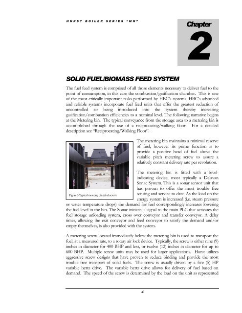
The metering bin maintains a minimal reserve<br />
of fuel, however its prime function is to<br />
provide a positive head of fuel above the<br />
variable pitch metering screw to assure a<br />
relatively constant delivery rate per revolution.<br />
The metering bin is fitted with a levelindicating<br />
device, most typically a Delavan<br />
Sonac <strong>System</strong>. This is a sonar sensor unit that<br />
has proven to offer the most trouble free<br />
Figure 3 Typical metering bin (dual screw)<br />
sensing and service to date. As the load on the<br />
energy system is increased (i.e. steam pressure<br />
or water temperature drops) the demand for fuel correspondingly increases lowering<br />
the fuel level in the bin. The Sonac initiates a signal to the main PLC that activates the<br />
fuel storage unloading system, cross over conveyor and transfer conveyor. A delay<br />
timer, allowing the exit conveyor and feed conveyor to satisfy the demand and/or<br />
empty themselves, is also provided with the system.<br />
A metering screw located immediately below the metering bin is used to transport the<br />
fuel, at a measured rate, to a rotary air lock device. Typically, the screw is either nine (9)<br />
inches in diameter for 400 BHP and less, or twelve (12) inches in diameter for up to<br />
600 BHP. Multiple screw units may be used for larger applications. <strong>Hurst</strong> utilizes<br />
aggressive screw designs that have proven to reduce binding and provide the most<br />
trouble free transport of solid fuels. The screw is usually driven by a five (5) HP<br />
variable hertz drive. The variable hertz drive allows for delivery of fuel based on<br />
demand. The speed of the screw is determined by the load on the unit as represented<br />
4<br />
Chapter<br />
2