Component & System Guide - Hurst Boiler
Component & System Guide - Hurst Boiler
Component & System Guide - Hurst Boiler

Create successful ePaper yourself
Turn your PDF publications into a flip-book with our unique Google optimized e-Paper software.
H U R S T B O I L E R S E R I E S “ M H ”<br />
in the plenum region below gasification/floor level. The wind box is fitted with slidetype<br />
dampers along both of its longitudinal sides to allow plenum air to surround the<br />
retort. The flanged edges of the retort are fitted with slotted cast iron grates that extend<br />
above floor level. As the fuel is forced into the retort it spills over the lip/ledge formed<br />
by the grates. The slots allow air to pass through the grates and it is at this point that<br />
the gasification process begins. While in units of 400 BHP and less the retort is located<br />
centrally in the combustion/gasification chamber, in larger units the retort is positioned<br />
closer to the supply end of the fuel system and employs pin hole grates located ahead<br />
of the retort. The pinhole grates are supplied air from the common plenum air supply.<br />
This air plenum has been compartmentalized and is equipped with slide-type dampers<br />
to regulate the air pressure of the separate zones. More pressure where the fuel is<br />
deepest and less where the ash burnout occurs.<br />
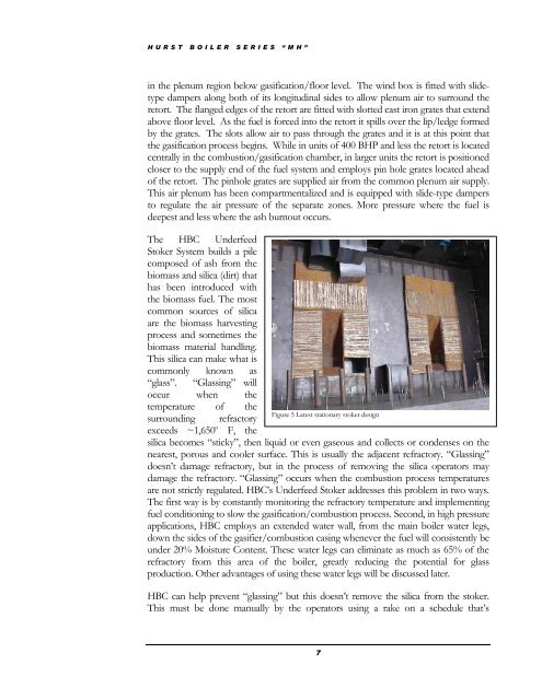
The HBC Underfeed<br />
Stoker <strong>System</strong> builds a pile<br />
composed of ash from the<br />
biomass and silica (dirt) that<br />
has been introduced with<br />
the biomass fuel. The most<br />
common sources of silica<br />
are the biomass harvesting<br />
process and sometimes the<br />
biomass material handling.<br />
This silica can make what is<br />
commonly known as<br />
“glass”. “Glassing” will<br />
occur when the<br />
temperature of the<br />
surrounding refractory<br />
exceeds ~1,650 o Figure 5 Latest stationary stoker design<br />
F, the<br />
silica becomes “sticky”, then liquid or even gaseous and collects or condenses on the<br />
nearest, porous and cooler surface. This is usually the adjacent refractory. “Glassing”<br />
doesn’t damage refractory, but in the process of removing the silica operators may<br />
damage the refractory. “Glassing” occurs when the combustion process temperatures<br />
are not strictly regulated. HBC’s Underfeed Stoker addresses this problem in two ways.<br />
The first way is by constantly monitoring the refractory temperature and implementing<br />
fuel conditioning to slow the gasification/combustion process. Second, in high pressure<br />
applications, HBC employs an extended water wall, from the main boiler water legs,<br />
down the sides of the gasifier/combustion casing whenever the fuel will consistently be<br />
under 20% Moisture Content. These water legs can eliminate as much as 65% of the<br />
refractory from this area of the boiler, greatly reducing the potential for glass<br />
production. Other advantages of using these water legs will be discussed later.<br />
HBC can help prevent “glassing” but this doesn’t remove the silica from the stoker.<br />
This must be done manually by the operators using a rake on a schedule that’s<br />
7