Component & System Guide - Hurst Boiler
Component & System Guide - Hurst Boiler
Component & System Guide - Hurst Boiler

You also want an ePaper? Increase the reach of your titles
YUMPU automatically turns print PDFs into web optimized ePapers that Google loves.
H U R S T B O I L E R S E R I E S “ M H ”<br />
Operation of the feed water pumps (on/off or variable speed) is controlled by a pump<br />
control --- this is a pump control not a flow control. The pump control is located on<br />
the side of the boiler at normal boiler water level --- a sight glass is attached to allow a<br />
visual indication of level. The control has an internal float which senses changes in<br />
water level and mechanically actuates switches that start and stop --- it supplies the<br />
control voltage for the pump motor starter --- the designated pump as the boiler level<br />
dictates. Each pump is protected electrically by thermal overloads located in the motor<br />
starters and a three-phase circuit breaker or fuses.<br />
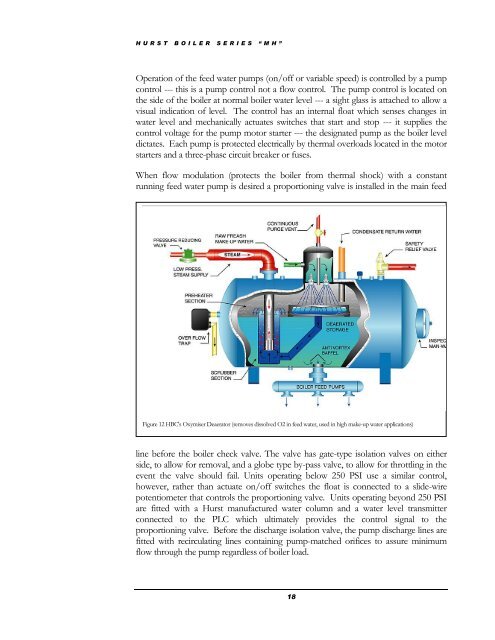
When flow modulation (protects the boiler from thermal shock) with a constant<br />
running feed water pump is desired a proportioning valve is installed in the main feed<br />
Figure 12 HBC's Oxymiser Deaerator (removes dissolved O2 in feed water, used in high make-up water applications)<br />
line before the boiler check valve. The valve has gate-type isolation valves on either<br />
side, to allow for removal, and a globe type by-pass valve, to allow for throttling in the<br />
event the valve should fail. Units operating below 250 PSI use a similar control,<br />
however, rather than actuate on/off switches the float is connected to a slide-wire<br />
potentiometer that controls the proportioning valve. Units operating beyond 250 PSI<br />
are fitted with a <strong>Hurst</strong> manufactured water column and a water level transmitter<br />
connected to the PLC which ultimately provides the control signal to the<br />
proportioning valve. Before the discharge isolation valve, the pump discharge lines are<br />
fitted with recirculating lines containing pump-matched orifices to assure minimum<br />
flow through the pump regardless of boiler load.<br />
18