Component & System Guide - Hurst Boiler
Component & System Guide - Hurst Boiler
Component & System Guide - Hurst Boiler

You also want an ePaper? Increase the reach of your titles
YUMPU automatically turns print PDFs into web optimized ePapers that Google loves.
H U R S T B O I L E R S E R I E S “ M H ”<br />
designed with an optimum cooling profile. Safeties are provided on all access doors to<br />
protect the operator during the stoking process.<br />
The HBC Pneumatic Stoker <strong>System</strong> is specifically designed for the combustion of dry<br />
(20% Moisture Content, wet basis) biomass fuels with very low silica content. This<br />
type of stoker has developed a dedicated following over many years use. The<br />
pneumatic stoker does have a few drawbacks in all its implementations. The fuel<br />
distribution usually is inconsistent with heavy fuel particles settling on the nearest<br />
grates, lighter particles farther out on the grate and the lightest particles never even<br />
reaching the grates (instant particulate that must be collected later). The grates are left<br />
exposed to the extremely turbulent, heated atmosphere of the chamber and WILL<br />
degrade prematurely. Finally, the use of air to introduce the fuel to the combustion<br />
zone negates the possibility of gasification and this excess air is extremely difficult to<br />
control while maintaining the optimum emission characteristics. Despite these<br />
drawbacks, the market demands that HBC continue to offer this design as an option<br />
The HBC Underfeed Stoker <strong>System</strong> has evolved from the Frederick underfeed coal<br />
stoker developed in the early 1900's. This technology has been adapted to our solid<br />
fuel/biomass fired systems. The underfeed stoker has proven over the last 20 years to<br />
be the most effective method of introducing low to medium silica/ash content fuels<br />
into the gasification zone on the market.<br />
The eight (8) or ten (10) inch diameter, based on application, constant speed stoker<br />
screw supplies fuel to the rectangular bathtub-shaped retort located below furnace floor<br />
level. The stoker screw tube, sch. 80 pipe, which encloses the screw is fitted with both<br />
a temperature sensor, to initiated a water spray should the temperature inside the tube<br />
rise above a preset amount --- a fire prevention mechanism --- and, in applications<br />
where dry (low moisture content) fuel is anticipated, a water spray nozzle to condition<br />
the fuel to the desired moisture content. It has<br />
been found that extremely dry fuel can adversely<br />
affect the operating conditions of the unit. The<br />
conditioning system is tied to a temperature UDC<br />
that opens or closes a solenoid in the spray line.<br />
Spray quantity is controlled by manually adjusting a<br />
needle valve attached to flow meter in the line.<br />
The stoker screw is designed to force fuel into the<br />
retort. In so doing, an air seal (“fuel plug”) is<br />
maintained within the stoker screw tube further<br />
preventing the intrusion of air through the fuel<br />
system.<br />
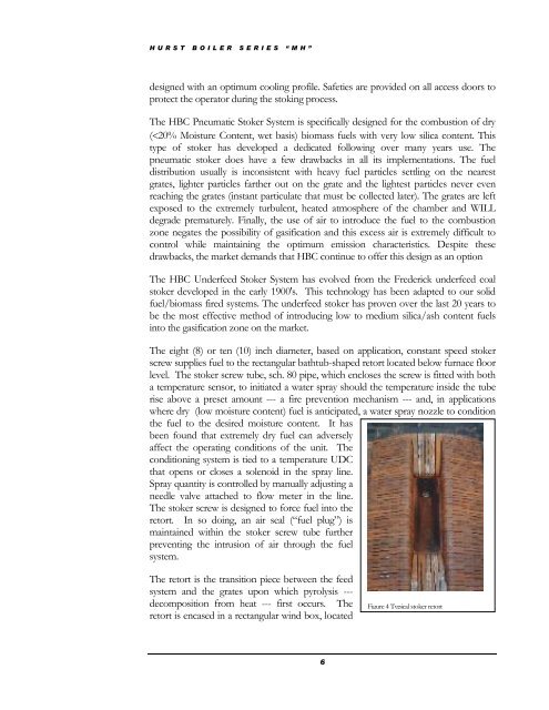
The retort is the transition piece between the feed<br />
system and the grates upon which pyrolysis ---<br />
decomposition from heat --- first occurs. The<br />
retort is encased in a rectangular wind box, located<br />
6<br />
Figure 4 Typical stoker retort