Manual for Class D wheeled extinguishers.pdf - Amerex Corporation
Manual for Class D wheeled extinguishers.pdf - Amerex Corporation
Manual for Class D wheeled extinguishers.pdf - Amerex Corporation

You also want an ePaper? Increase the reach of your titles
YUMPU automatically turns print PDFs into web optimized ePapers that Google loves.
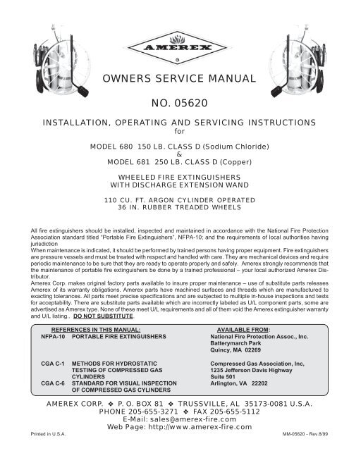
OWNERS SERVICE MANUAL<br />
NO. 05620<br />
INSTALLATION, OPERATING AND SERVICING INSTRUCTIONS<br />
<strong>for</strong><br />
MODEL 680 150 LB. CLASS D (Sodium Chloride)<br />
&<br />
MODEL 681 250 LB. CLASS D (Copper)<br />
WHEELED FIRE EXTINGUISHERS<br />
WITH DISCHARGE EXTENSION WAND<br />
110 CU. FT. ARGON CYLINDER OPERATED<br />
36 IN. RUBBER TREADED WHEELS<br />
All fire <strong>extinguishers</strong> should be installed, inspected and maintained in accordance with the National Fire Protection<br />
Association standard titled “Portable Fire Extinguishers”, NFPA-10; and the requirements of local authorities having<br />
jurisdiction<br />
When maintenance is indicated, it should be per<strong>for</strong>med by trained persons having proper equipment. Fire <strong>extinguishers</strong><br />
are pressure vessels and must be treated with respect and handled with care. They are mechanical devices and require<br />
periodic maintenance to be sure that they are ready to operate properly and safely. <strong>Amerex</strong> strongly recommends that<br />
the maintenance of portable fire <strong>extinguishers</strong> be done by a trained professional – your local authorized <strong>Amerex</strong> Distributor.<br />
<strong>Amerex</strong> Corp. makes original factory parts available to insure proper maintenance – use of substitute parts releases<br />
<strong>Amerex</strong> of its warranty obligations. <strong>Amerex</strong> parts have machined surfaces and threads which are manufactured to<br />
exacting tolerances. All parts meet precise specifications and are subjected to multiple in-house inspections and tests<br />
<strong>for</strong> acceptability. There are substitute parts available which are incorrectly labeled as U/L component parts, some are<br />
advertised as <strong>Amerex</strong> type. None of these meet U/L requirements and all of them void the <strong>Amerex</strong> extinguisher warranty<br />
and U/L listing.. DO NOT SUBSTITUTE.<br />
REFERENCES IN THIS MANUAL: AVAILABLE FROM:<br />
NFPA-10 PORTABLE FIRE EXTINGUISHERS National Fire Protection Assoc., Inc.<br />
Batterymarch Park<br />
Quincy, MA 02269<br />
CGA C-1 METHODS FOR HYDROSTATIC Compressed Gas Association, Inc,<br />
TESTING OF COMPRESSED GAS 1235 Jefferson Davis Highway<br />
CYLINDERS Suite 501<br />
CGA C-6 STANDARD FOR VISUAL INSPECTION Arlington, VA 22202<br />
OF COMPRESSED GAS CYLINDERS<br />
AMEREX CORP. P. O. BOX 81 TRUSSVILLE, AL 35173-0081 U.S.A.<br />
PHONE 205-655-3271 FAX 205-655-5112<br />
E-Mail: sales@amerex-fire.com<br />
Web Page: http://www.amerex-fire.com<br />
Printed in U.S.A. MM-05620 - Rev.8/99
AMEREX CORPORATION DOES NOT SERVICE, MAINTAIN OR RECHARGE FIRE EXTINGUISHERS. THIS MANUAL<br />
IS PUBLISHED AS A GUIDE TO ASSIST QUALIFIED SERVICE PERSONNEL IN THE INSPECTION, MAINTENANCE<br />
AND RECHARGE OF AMEREX FIRE EXTINGUISHERS ONLY. NO INSTRUCTION MANUAL CAN ANTICIPATE ALL<br />
POSSIBLE MALFUNCTIONS THAT MAY BE ENCOUNTERED IN THE SERVICE OF FIRE EXTINGUISHERS. DUE TO<br />
THE POSSIBILITY THAT PRIOR SERVICE PERFORMED ON THIS EQUIPMENT MAY HAVE BEEN IMPROPERLY<br />
DONE, IT IS EXTREMELY IMPORTANT THAT ALL WARNINGS, CAUTIONS AND NOTES IN THIS MANUAL BE CARE-<br />
FULLY OBSERVED. FAILURE TO HEED THESE INSTRUCTIONS COULD RESULT IN SERIOUS INJURY. AMEREX<br />
ASSUMES NO LIABILITY FOR SERVICE, MAINTENANCE OR RECHARGE OF FIRE EXTINGUISH-<br />
ERS BY PUBLISHING THIS MANUAL<br />
PREP PREPARING<br />
PREP ARING YOUR OUR NEW NEW EXTINGUISHER EXTINGUISHER FOR FOR USE<br />
USE<br />
WARNING: THIS FIRE EXTINGUISHER IS SHIPPED FROM THE FACTORY EMPTY. AFTER INITIAL PREPARATIONS,<br />
CAREFULLY FOLLOW THE RECHARGING INSTRUCTIONS BEFORE REPLACING IT INTO SERVICE.<br />
1. Remove all wrappings, straps and pallet retaining bolts.<br />
2. Examine the extinguisher <strong>for</strong> shipping damage. Check to make sure that you have received the <strong>Class</strong> D powder<br />
charge containers and Extension Wand which are packaged with the extinguisher.<br />
3. Fill the extinguisher by carefully following the RECHARGE instructions.<br />
4. Remove the ARGON cylinder protective shipping cap. Save the cap as it must be installed whenever a<br />
charged ARGON cylinder is transported.<br />
5. Check the ARGON cylinder pressure. The gauge should read approximately 2015 psig (13.9 mPa) at 70°F<br />
(21°C) ambient temperature. See the “Troubleshooting Guide” <strong>for</strong> pressure-temperature allowances. The lead<br />
wire seal should be intact.<br />
6. Connect the Argon supply hose firmly to the Argon cylinder valve. Make sure that there are no kinks in this<br />
hose.<br />
7. Disconnect the discharge hose assembly from the agent cylinder. Make sure that the hose and nozzle (and<br />
Extension Wand) are unobstructed. Reconnect the discharge hose to the agent cylinder and with the shut-off<br />
valve in the closed (<strong>for</strong>ward) position, properly coil the hose onto the storage rack. Place the shut-off nozzle (or<br />
Extension Wand if used) into the retaining clips [see hose coiling - last page].<br />
8. Record the date the extinguisher is being placed into service on the inspection tag and attach it to the unit.<br />
9. Remove the CAUTION (NOT CHARGED) tag.<br />
INSTALLATION<br />
WARNING: THE MODEL 680 CLASS D FIRE EXTINGUISHER HAS BEEN TESTED AND APPROVED FOR CLASS D<br />
FIRES INVOLVING MAGNESIUM, SODIUM, POTASSIUM OR POTASSIUM ALLOYS ONLY.<br />
THE MODEL 681 CLASS D FIRE EXTINGUISHER HAS BEEN TESTED AND APPROVED FOR CLASS D<br />
FIRES INVOLVING LITHIUM ONLY.<br />
DO NOT USE EITHER EXTINGUISHER ON CLASS A, B OR C FIRES.<br />
Do not place this extinguisher close to a potential fire hazard. <strong>Amerex</strong> recommends location at a 50 foot minimum<br />
distance from the hazard with an unobstructed access. Avoid placing it in an extremely hot or cold place. The temperature<br />
range <strong>for</strong> this extinguisher is –40° to 120°F (-40° to 49°C). Keep the extinguisher clean and free from dirt, ice,<br />
chemicals and other contaminants which may interfere with its proper operation.<br />
DO NOT FUNCTIONALLY TEST THIS FIRE EXTINGUISHER. Testing or any use may cause the extinguisher to<br />
gradually lose pressure and become ineffective.
OPERATION<br />
CAUTION: PERSONS EXPECTED TO USE THIS EXTINGUISHER SHOULD BE TRAINED IN INITIATING ITS OPERATION<br />
AND IN THE PROPER FIRE FIGHTING TECHNIQUE. FAMILIARIZE ALL PERSONNEL WITH THIS INFORMA-<br />
TION BEFORE AN EMERGENCY OCCURS.<br />
1. Move the extinguisher to within approximately 25 feet of the fire site. REMOVE RING<br />
(SAFETY) PIN.<br />
Pull “T” handle to OPEN ARGON VALVE. This will pressurize the extinguisher.<br />
2. Remove nozzle from the mount, and with the nozzle lever in the CLOSED position,<br />
PULL HOSE FROM RACK AND START BACK 15 FEET from the fire.<br />
Note: When using the wand applicator START BACK 6 FEET FROM FIRE.<br />
3. OPEN NOZZLE SHUT-OFF slowly by pulling handle fully towards you (hold the nozzle<br />
firmly and be prepared <strong>for</strong> a discharge recoil). COVER ALL BURNING METAL WITH<br />
POWDER.<br />
4. REAPPLY AGENT TO HOT SPOTS until the fire is fully extinguished.<br />
DISCHARGE TIME (APPROXIMATE)<br />
Model 680 – 80 Seconds Model 681 – 120 Seconds<br />
EFFECTIVE RANGE OF THE AGENT THROW<br />
With Nozzle (both units) – 20 to 30 feet<br />
With Applicator (both units) – 4 to 6 feet<br />
HOSE LENGTH - 25 FEET<br />
RECHARGE EXTINGUISHER IMMEDIATELY AFTER ANY USE <br />
SHUTDOWN<br />
1. After making sure that the fire has been completely extinguished, push the nozzle lever <strong>for</strong>ward to the CLOSED<br />
position.<br />
2. Close the Argon cylinder valve (push “T” handle to closed position).<br />
3. Tip extinguisher over to rest on wheels and handle, then slowly open the nozzle lever again to clear the hose of<br />
chemical agent and pressure (be prepared <strong>for</strong> recoil and discharge of agent).<br />
WARNING: MAKE SURE THAT ALL PRESSURE HAS ESCAPED BEFORE FURTHER DISASSEMBLY.<br />
4. Stand the extinguisher upright after complete depressurization.<br />
Note: Argon pressure in the agent cylinder cannot escape through a disconnected pressurizing hose due to a<br />
check valve in the system. Always be careful when removing the fill cap.<br />
5. Coil the extinguisher hose onto the storage rack and position the nozzle (and/or Extension Wand) onto the<br />
mount in preparation <strong>for</strong> transport to the recharge location.<br />
WARNING: THE SHIPPING CAP MUST BE INSTALLED ON THE ARGON CYLINDER PRIOR TO TRANSPORT<br />
TO THE RECHARGE LOCATION.<br />
INSPECTING THE EXTINGUISHER<br />
INSPECTION (NFPA-10 4.2.1) is a “quick check” that an extinguisher is available and will operate. It is intended to give<br />
reasonable assurance that the extinguisher is fully charged and operable. This is done by seeing that it is in its<br />
designed place, that it has not bee actuated or tampered with, and that there is no obvious physical damage or<br />
condition to prevent operation.
PERIODIC INSPECTION PROCEDURES<br />
(Monthly or more often if circumstances dictate)<br />
(NFPA-10 4-3.2) A “quick check” should be made of the extinguisher <strong>for</strong> the following:<br />
1. Located in designated place.<br />
2. No obstructions to access or visibility.<br />
3. Operating instructions on nameplate and facing outward.<br />
4. Seals and tamper indicators not broken or missing.<br />
5. Determine fullness by weighing on a scale with adequate capacity.<br />
6. Examine <strong>for</strong> obvious physical damage, corrosion, leakage or clogged nozzle.<br />
7. Pressure gauge (Argon cylinder) reading in the operable area.<br />
MAINTENANCE<br />
MAINTENANCE (NFPA-10 4-4.1 & 4-4.2) At least once a year (or more frequently if indicated by an inspection),<br />
MAINTENANCE should be per<strong>for</strong>med. MAINTENANCE is a “thorough check” of the extinguisher. It is intended<br />
to give maximum assurance that an extinguisher will operate effectively and safely. It includes a thorough<br />
examination and any necessary repair or replacement. It will normally reveal the need <strong>for</strong> hydrostatic testing.<br />
Note: NFPA-10 (4-3.2) spells out <strong>wheeled</strong> extinguisher maintenance procedures. Para. 4-4.1.3 requires that<br />
REGULATORS on <strong>wheeled</strong> <strong>extinguishers</strong> be checked annually to meet manufacturer’s “dead set” and<br />
“minimum flow” recommendations.<br />
The Getz Mfg. P/N: 52576 Wheeled Extinguisher Service Kit is available so that you can per<strong>for</strong>m these<br />
required functions. Getz part numbers from the kit are referenced in this manual.<br />
ANNUAL MAINTENANCE PROCEDURES<br />
WARNING: BEFORE SERVICING BE SURE THE EXTINGUISHER AGENT CYLINDER IS NOT PRESSURIZED.<br />
Note: This procedure will be best accomplished with the extinguisher in an upright position and on a level surface.<br />
1. Clean extinguisher to remove dirt, grease or <strong>for</strong>eign material. Check to make sure that the instruction nameplate<br />
is securely fastened and legible. Inspect the cylinders <strong>for</strong> corrosion, abrasion, dents or weld damage. If<br />
damage is found, hydrostatically test in accordance with instructions in CGA Pamphlet C-1 and C-6 and NFPA<br />
Pamphlet 10.<br />
2. Inspect the extinguisher <strong>for</strong> damaged, missing or substitute parts. A careful inspection should be made of the<br />
safety relief to make sure that it has not ruptured, corroded or been tampered with. Only factory replacement<br />
parts are approved <strong>for</strong> use on <strong>Amerex</strong> fire <strong>extinguishers</strong>.<br />
3. Check the date of manufacture on the extinguisher nameplate or on the agent cylinder dome. The agent<br />
cylinder assembly and discharge hose assembly must be hydrostatically tested every 12 years. Test pressure<br />
<strong>for</strong> the agent cylinder is 500 psi (3448 kPa). Test pressure <strong>for</strong> the hose assembly is 300 psi (0268 kPa).<br />
4. Check the hydrostatic test date on the crown of the Argon cylinder. The Argon cylinder must be retested in<br />
accordance with D.O.T. regulations every 5 years.<br />
5. Check the gauge on the Argon cylinder. If the pressure is below 1700 psig (11.7 mPa) repressurize the cylinder<br />
to 2015 psig (13.9 mPa) or replace it. A low pressure may indicate leakage. Check <strong>for</strong> leaks. A low gauge<br />
reading may also result from low temperature. See the temperature/pressure relationship chart in the “Troubleshooting<br />
Guide”. Check the tamper indicator (lockwire seal) on the Argon valve and replace if necessary.<br />
6. Inspect the wheels to insure they rotate freely. Lubricate as required.<br />
WARNING: THE FOLLOWING STEPS SHOULD ONLY BE PERFORMED BY PROFESSIONALLY TRAINED AND QUALIFIED SERVICE<br />
PERSONNEL THOROUGHLY FAMILIAR WITH INDUSTRY SERVICE PROCEDURES AND SAFETY PRECAUTIONS AND<br />
HAVING THE NECESSARY EQUIPMENT TO PERFORM THE SERVICE PROPERLY.<br />
ALL EXTINGUISHER AND SERVICE EQUIPMENT COMPONENTS, FITTINGS AND ADAPTERS MUST BE IN GOOD CONDI-<br />
TION AND PROPERLY CONNECTED.
7. Disconnect the regulator from the agent cylinder. Visually examine the regulator and high pressure hose <strong>for</strong> signs<br />
of damage, corrosion or deterioration. To per<strong>for</strong>m the regulator static pressure, dead set and minimum pressure<br />
flow rate checks:<br />
a) Connect the proper service kit ADAPTER (P/N: 01740) to the low pressure outlet port of the regulator.<br />
b) Connect the service kit HOSE ASSEMBLY (P/N: 01410) and FLOW CHAMBER (P/N: 01250) to the<br />
regulator low pressure port adapter.<br />
8. Make sure all service kit connections are secure and that the kit flow chamber is CLOSED. Check the ARGON<br />
cylinder pressure to ensure that it is within the acceptable operating range. Hold the kit flow chamber in one<br />
hand and slowly open the Argon cylinder (with either “T” handle operating lever or by turning the handwheel if so<br />
equipped). Observe flow chamber pressure reading to see if it is within the recommended static dead set<br />
pressure parameters <strong>for</strong> the Models 680 & 681 regulator listed below.<br />
Regulator Type Static Dead Set Pressure Minimum Flow Pressure<br />
Victor 120 ± 10 PSI 110 PSI minimum<br />
WARNING: IF THE PRESSURE READING EXCEEDS THE GIVEN PARAMETERS, QUICKLY CLOSE THE ARGON<br />
CYLINDER “T” HANDLE OR HANDWHEEL VALVE AND VENT THE PRESSURE BY OPENING THE FLOW<br />
CHAMBER BALL VALVE.<br />
REGULATORS CANNOT BE FIELD ADJUSTED. THEY MUST BE REPLACED IF FOUND TO BE OUT OF TOLERANCE.<br />
9. Observe the proper regulator static dead set pressure <strong>for</strong> a minimum of one minute, then fully open the flow<br />
chamber valve <strong>for</strong> 1 - 2 seconds. Observe the pressure reading to ensure that the flow pressure does not drop<br />
below the minimum specified. Close the Argon cylinder valve after the test and vent the flow chamber pressure<br />
by opening the flow chamber valve.<br />
Note: Prior to per<strong>for</strong>ming the minimum flow check, make sure that the nitrogen cylinder valve (“T” handle or<br />
handwheel) is FULLY OPEN so that it does not restrict or alter the flow readings.<br />
WARNING: ALWAYS OPEN THE SHUTOFF NOZZLE HANDLE SLOWLY. ANY PRESSURE IN THE AGENT CYLINDER<br />
WILL CAUSE THE EXTINGUISHER TO DISCHARGE. BE PREPARED FOR A POSSIBLE DISCHARGE AND<br />
NOZZLE RECOIL. ANY EVIDENCE OF AGENT IN THE NOZZLE INDICATES THAT THE UNIT MAY HAVE<br />
BEEN USED AND THE USE NOT REPORTED.<br />
10. Disconnect the discharge hose from the agent cylinder. Check the couplings, hose and hose gaskets <strong>for</strong> damage<br />
or deterioration – replace as necessary.<br />
11. To per<strong>for</strong>m an operational integrity check on the discharge hose and nozzle combination:<br />
a) Connect the test kit hose adapter to the female end of the discharge hose.<br />
b) Close the discharge nozzle shut-off lever and properly secure it.<br />
c) Connect a properly regulated and verified nitrogen pressure source (set to the extinguisher operating<br />
pressure [110 - 130 psi] to the test kit hose adapter.<br />
d) Slowly pressurize the discharge hose/nozzle assembly to the extinguisher operating pressure and check<br />
<strong>for</strong> leaks or distortion.<br />
e) Operate the nozzle lever to ensure proper operation and to clear the hose of any obstructions (if hose is<br />
obstructed - refer to the TROUBLE SHOOTING section of this manual.<br />
f) Close the nitrogen pressure source and relieve remaining pressure by slowly and fully opening the nozzle lever.<br />
12. Remove the agent cylinder cap and examine it closely <strong>for</strong> signs of damage, cracks or thread wear. Clean the<br />
agent cylinder fill cap threads and thread vent port on the cap with a stiff bristle nylon brush. Remove the fill cap<br />
gasket and check <strong>for</strong> wear, cracks or tears - replace if necessary. Lightly lubricate the gasket with Visilox 711<br />
and reinstall.<br />
13. Examine the condition of the chemical agent <strong>for</strong> proper type and condition. Replace chemical that is contaminated,<br />
caked or different than the type indicated on the nameplate (label). Do not trust to the “height” of the<br />
chemical when determining agent fill. Dry powder will settle and the only true indication of agent fill is to weigh<br />
the extinguisher and compare with the weight indicated on the nameplate (label).<br />
14. Place the service kit VENT SPACER (P/N: 01530) on top of the agent cylinder fill opening collar. Check again to<br />
see that the fill cap thread vent is clean and that the agent ill cap gasket is in place. Install the agent fill cap<br />
securely over the vent spacer.
CAUTION: STEP 15 - THE AGENT CYLINDER CAP THREADS MUST BE CLEAR AND THE CAP SECURELY INSTALLED<br />
ONTO THE VENT SPACER AND AGENT CYLINDER TO ALLOW PRESSURE TO SLOWLY VENT AFTER PER-<br />
FORMING THE SIPHON TUBE CLEARING AND GAS TUBE INTEGRITY CHECKS.<br />
15. To per<strong>for</strong>m a siphon tube clearing and gas tube integrity check:<br />
a) Remove the service kit AGENT HOSE ADAPTER (P/N: 01455) from the discharge hose assembly and<br />
install it securely onto the agent cylinder siphon tube outlet.<br />
b) Use a regulated Argon pressure source, set to the extinguisher operating pressure (110 PSI) and briefly<br />
pressurize the agent cylinder (the siphon tube should clear within a couple of seconds and the agent<br />
cylinder pressure slowly vent from the fill cap thread vent). Pressure and/or dry powder leaking from<br />
the gas inlet port, where the regulator was installed, will indicate a defective gas tube. This will require<br />
emptying the agent cylinder and replacing the gas tube.<br />
c) Close the Argon pressure source and allow all pressure to slowly vent from the thread vent port on the fill cap.<br />
d) AFTER ALL PRESSURE HAS BEEN RELIEVED, SLOWLY OPEN THE FILL CAP AND -<br />
REMOVE THE TEST KIT VENT SPACER.<br />
e) Re-examine the <strong>Class</strong> D dry powder agent to determine if any obstructions have been cleared from the<br />
siphon tube and have risen to the surface.<br />
f) Clean the fill cap and agent cylinder thread surfaces. Securely install the fill cap gasket and fill cap.<br />
16. Disconnect the service kit quick connect adapter from the low pressure port of the regulator and reinstall the<br />
regulator securely to the agent cylinder.<br />
17. Disconnect the high pressure hose from the Argon cylinder valve. Securely install the service kit ARGON/<br />
NITROGEN CYLINDER PRESSURE CHECK GAUGE ASSEMBLY (P/N: 01300) to the Argon cylinder valve<br />
outlet and verify the indicated cylinder gauge pressure. Argon pressure should con<strong>for</strong>m to the temperature<br />
correction chart provided in the TROUBLE SHOOTING section of this manual. Close the Argon cylinder valve<br />
and disconnect the Pressure Check Gauge Assembly.<br />
WARNING: IF THE ARGON CYLINDER VALVE HAS A “T” HANDLE QUICK OPENING OR QUICK OPEN-<br />
ING TRIP LEVER RELEASE, THE SAFETY VENT PLUG (P/N: 01560) MUST BE INSTALLED<br />
TO PROTECT SERVICE PERSONNEL FROM A HIGH VELOCITY DISCHARGE IN CASE THE<br />
LEVER IS ACCIDENTALLY OPENED.<br />
18. Install a new <strong>Amerex</strong> P/N: 7411 Moisture Seal per instructions in the package. Securely connect the discharge<br />
hose to the extinguisher. When assembling the hose to the agent cylinder or nozzle to the hose, tighten the<br />
coupling ¼ turn after contacting the hose gasket.<br />
19. Coil the hose onto the extinguisher hose rack using the reverse loop procedure (see instructions later in this<br />
manual). Install the shut-off nozzle (and/or Extension Wand) with the lever in the CLOSED (<strong>for</strong>ward) position on<br />
the mount.<br />
20. Remove the safety vent plug from the Argon cylinder. Re-connect the high pressure hose securely to the Argon<br />
cylinder valve. Wipe the extinguisher clean. Record the service data on the inspection tag according to NFPA-<br />
10 requirements and attach to the extinguisher. Return the extinguisher is in its proper location.<br />
RECHARGE<br />
RECHARGING (NFPA-10 4-2.3) is the replacement of the extinguishing agent and also includes the expellant <strong>for</strong><br />
this type of extinguisher.<br />
RECHARGE PROCEDURE<br />
WARNING: BEFORE ATTEMPTING TO RECHARGE BE SURE THIS EXTINGUISHER IS COMPLETELY DEPRESSURIZED.<br />
THERE IS A CHECK VALVE IN THE SYSTEM WHICH PREVENTS ARGON PRESSURE FROM ESCAPING<br />
FROM THE AGENT CYLINDER WHEN THE ARGON SUPPLY HOSE IS DISCONNECTED. THE AGENT CYLIN-<br />
DER MAY BE PRESSURIZED EVEN THOUGH NO PRESSURE ESCAPES FROM THE ARGON CYLINDER HIGH<br />
PRESSURE HOSE CONNECTION.
1. TO DEPRESSURIZE:<br />
a) Close the Argon cylinder valve.<br />
b) Carefully tip extinguisher over until it rests on both wheels and handle. (in this position much of the agent will<br />
remain in the cylinder.)<br />
c) Open the nozzle lever slowly to discharge all remaining agent and pressure. (be prepared <strong>for</strong> a nozzle recoil).<br />
d) Insure that all pressure has escaped be<strong>for</strong>e further disassembly.<br />
e) Return extinguisher to the upright position after complete depressurization.<br />
2. Carefully remove the fill cap. Detach discharge hose from the agent cylinder and the nozzle assembly from the<br />
hose. Blow out any chemical agent remaining in the hose. Clean hose and container fittings and gaskets.<br />
Replace gaskets as necessary.<br />
3. Inspect the cylinder interior following CGA Visual Inspection Standard, Pamphlet C-6.<br />
4. Per<strong>for</strong>m MAINTENANCE-SERVICE PROCEDURES 1 through 3, 6 and 7. All parts should be inspected, clean<br />
and replaced if necessary.<br />
5. Detach hose from the Argon cylinder, install the shipping cap, unscrew the wing nuts and remove the Argon<br />
cylinder from the extinguisher<br />
6. Fill the agent cylinder with the proper amount of <strong>Amerex</strong> <strong>Class</strong> D Powder (Model 680 – capacity 150 lbs., Super<br />
D [Sodium Chloride] or Model 681 – capacity 250 lbs. Copper). Lubricate the fill cap gasket. Install the fill cap<br />
and tighten securely.<br />
WARNING: REPLACE ANY CHEMICAL THAT IS CONTAMINATED OR CAKED. DO NOT OVERFILL THE<br />
EXTINGUISHER - THIS COULD CAUSE MALFUNCTION. NEVER MIX TYPES OF AGENTS.<br />
7. Install an <strong>Amerex</strong> P/N 10904 110 cu. ft. ARGON cylinder (pressurized to 2015 psi), remove the shipping cap,<br />
place on the extinguisher and attach the Argon hose. The Ring (safety) Pin and tamper indicator (lockwire seal)<br />
[“T” handle valve] or lead wire seal [handwheel valve] must be in place.<br />
8. Reattach the hose to the extinguisher (tighten hand tight plus a ¼ turn). Properly coil the hose onto the storage<br />
rack. Reattach the shutoff nozzle (and/or Extension Wand) firmly to the hose and store it in the mount with the<br />
shutoff lever in the CLOSED (<strong>for</strong>ward) position.<br />
9. Record the service date on the inspection tag and place the extinguisher in its proper location.<br />
TROUBLESHOOTING GUIDE<br />
WARNING: BEFORE ATTEMPTING TO CORRECT ANY LEAKAGE PROBLEM, BE SURE THAT THE AGENT CYLINDER<br />
IS COMPLETELY DEPRESSURIZED. ALWAYS USE CAUTION WHEN OPENING THE SHUTOFF NOZZLE,<br />
AGENT CLINDER CAP OR ANY OTHER CONNECTION AS A LEAKING ARGON VALVE SEAT MAY HAVE<br />
PRESSURIZED THE AGENT CONTAINER. REFER TO THE PREVIOUS PAGE IN THE RECHARGE PROCE-<br />
DURE FOR PROPER METHOD OF DEPRESSURIZATION.<br />
PROBLEM CORRECTIVE ACTION<br />
1. Argon cylinder gauge reads low or high. 1. Temperature may have affected the pressure reading.<br />
Temp. F 35° 70° 120°<br />
Temp. C 2° 21° 49°<br />
Recommended Pressure<br />
psig 1880 2015 2200<br />
mPa 13.0 13.9 15.2<br />
Minimum Pressure<br />
psig 1590 1700 1900<br />
mPa 11.0 11.7 13.1<br />
No corrective action is required if the pressure is within<br />
parameters stated above.
13<br />
2. Argon pressure is too low. Valve is closed. 2. Valve seat has leaked and has pressurized the agent cylinder.<br />
Tamper seal is intact. Pressure in agent and Follow RECHARGE PROCEDURE <strong>for</strong> restoring the<br />
the Argon cylinders. extinguisher to service.<br />
3. Argon pressure is too low. Valve is closed. 3. Leakage in the Argon valve at other than the valve seat.<br />
Tamper seal is intact. No pressure observed Replace with a properly charged Argon cylinder<br />
in the agent cylinder.<br />
4. Unable to remove the agent cylinder cap. 4. Agent cylinder may be pressurized. Make no further attempt<br />
to remove the cap until this is checked. See the RECHARGE<br />
PROCEDURE <strong>for</strong> proper depressurization method.<br />
5. Argon supply hose cut, cracked or abraded. 5. Replace hose assembly with <strong>Amerex</strong> P/N: 06814.<br />
PARTS LIST<br />
<strong>for</strong><br />
150 / 250 LB. WHEELED CLASS D<br />
DRY POWDER Extinguishers with<br />
36 In. Steel Wheels w/ Rubber Treads<br />
110 CU. FT. Argon Cylinder<br />
Models 680 150 LB. Super D (Sodium Chloride)<br />
681 250 LB. Copper<br />
14<br />
10<br />
4<br />
1A<br />
9A<br />
HOSE (25 ft.) / WAND INSTALLATION<br />
1. Connect hose coupling to outlet on the extinguisher.<br />
Lay hose straight on ground to its full 50<br />
ft. length.<br />
Start first regular loop clockwise by placing over<br />
the top and between side brackets<br />
9<br />
ITEM<br />
PART<br />
STD.<br />
NO.<br />
NO. DESCRIPTION<br />
PKG.<br />
1 6993 Cap( Forged<br />
Brass)<br />
, Agent<br />
Cylinder<br />
1<br />
1A12576 Cap<br />
( Forged<br />
Brass)<br />
, Agent<br />
Cylinder<br />
with<br />
Pressure<br />
Indicator<br />
1<br />
2 2272 Gasket, Cap<br />
1<br />
3 1990 Bumper, Rubber<br />
12<br />
4 10915 ArgonPressureRegulator 1<br />
5 4195 LeadWireSeal<strong>for</strong>ArgonValve 12<br />
6 2233 Argon<br />
Cylinder<br />
Valve<br />
( Hand<br />
Wheel)<br />
with<br />
Gauge<br />
1<br />
6A12467 Argon<br />
Cylinder<br />
Valve<br />
( Quick<br />
Release)<br />
with<br />
Gauge<br />
6B6373 Valve<br />
Lever<br />
( " T"<br />
Handle<br />
with<br />
Roll<br />
Pin<br />
and<br />
Knobs)<br />
6C10213 Gauge-3000PSI 1<br />
6D9897 ValveStemAss'y 6<br />
6E0501 Spring 6<br />
7 1 0904<br />
Argon<br />
Cylinder,<br />
110<br />
cu.<br />
ft.<br />
, charged,<br />
Includi<br />
ng<br />
Valve,<br />
Gauge<br />
and<br />
Protective<br />
Cap<br />
1<br />
8 2234 PressurizingHoseAss'y 1<br />
9 10906 Retaining<br />
Strap<br />
( Top)<br />
with<br />
Hose<br />
Hanger<br />
-<br />
Argon<br />
Cylinder<br />
1<br />
9A11020 RetainingStrap( Bottom)<br />
- Argon<br />
Cylinder<br />
1<br />
1011970 Bolt, Washer<br />
and<br />
Wing<br />
Nut<br />
1<br />
1110910 Pictogram-680&681 1<br />
1210909 10911<br />
Nameplate<br />
( Mylar<br />
Label)<br />
- Non<br />
F.<br />
M.<br />
- 680<br />
681<br />
1<br />
1310917 Wheel<br />
Ass'y<br />
- 36"<br />
X 2 1/<br />
2"<br />
with<br />
Rubber<br />
Tread<br />
1<br />
1410903 HubCap-36" Wheels<br />
1<br />
157411 MoistureSeal 1<br />
163877 Gasket, Hose<br />
/ Nozzle<br />
6<br />
176279 BallValveAss'y 1<br />
186 467<br />
NozzleTip( . 312)<br />
1<br />
191 0913<br />
HoseAss'y-3/ 4"<br />
x 25<br />
Ft.<br />
1<br />
2011181 ExtensionWandAss'y 1<br />
2. The second loop is a REVERSE loop.<br />
Notice that the hose passes behind the loop on<br />
this reverse loop.<br />
If instructions are followed, the hose will<br />
uncoil without kinks.<br />
Reverse<br />
loop<br />
1<br />
1<br />
15<br />
16<br />
17<br />
18<br />
Quick Release<br />
Argon Valve<br />
19<br />
6A<br />
6C<br />
6B<br />
6D<br />
6E<br />
20<br />
3. The next loop is a regular “hose in front”<br />
loop. Adjust the loops so that they are approximately<br />
the same size and then attach<br />
the hose to the shutoff valve with either the<br />
extension wand or nozzle installed.