Ch15 Metal Extrusion And Drawing Processes
Ch15 Metal Extrusion And Drawing Processes
Ch15 Metal Extrusion And Drawing Processes

Create successful ePaper yourself
Turn your PDF publications into a flip-book with our unique Google optimized e-Paper software.
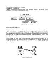
<strong>Metal</strong> <strong>Extrusion</strong> and <strong>Drawing</strong><br />
<strong>Processes</strong> and Equipment<br />
Text Reference: “Manufacturing Engineering and<br />
Technology”, Kalpakjian & Schmid, 6/e, 2010<br />
Chapter 15
<strong>Extrusion</strong><br />
A cylindrical billet is forced through a die<br />
(‘push’) (push) (‘push’)<br />
<strong>Drawing</strong><br />
The cross section of solid rod, wire, or<br />
tubing is is reduced reduced or or changed changed in in shape shape by<br />
by<br />
pulling it through a die (‘pull’)
FIGURE 15.1 Schematic illustration of the direct-extrusion direct extrusion process. p
<strong>Extrusion</strong><br />
Large deformations can take place without<br />
fracture because material is under triaxial<br />
compression<br />
Produce products with constant cross<br />
section; cut to length<br />
A A batch batch process; process; one one length length per per billet<br />
billet<br />
Low tool costs; Economic for large & short<br />
production runs<br />
runs<br />
Perform cold or at elevated temperatures;<br />
depends depends on on ductility ductility of material<br />
Materials: Al, Cu, Steel, Mg, Pb, other
Extruded Products<br />
Railings for sliding doors<br />
Window Window frames<br />
frames<br />
Tubing (various, constant, cross sections)<br />
Aluminum Aluminum ladder ladder frames<br />
frames<br />
Structural & architectural shapes<br />
Brackets; Brackets; Gears; Coat hangars<br />
Cold <strong>Extrusion</strong> (combine with forging)<br />
F Fasteners<br />
Components for automobiles, bicycles,<br />
motorcycles motorcycles, heavy machinery machinery, transportation<br />
transportation<br />
equipment
FIGURE 15.2 <strong>Extrusion</strong>s and examples of products made by<br />
sectioning off ff extrusions. Source: Source: Courtesy of f Plymouth l h Extruded d d<br />
Shapes.
<strong>Extrusion</strong> Process<br />
Direct (or Forward) <strong>Extrusion</strong><br />
Billet ll in chamber h b is pushed h d through h h die d by b hydraulic h d l<br />
ram<br />
Indirect (or (or Reverse, Inverted, Backward)<br />
<strong>Extrusion</strong><br />
The die moves toward the billet<br />
Hydrostatic <strong>Extrusion</strong><br />
Billet in chamber is surrounded by fluid<br />
L Lateral t l (or ( Side) Sid ) <strong>Extrusion</strong> E t i<br />
Impact <strong>Extrusion</strong><br />
Punch descends rapidly on blank which which is is extruded<br />
extruded<br />
backwards
FIGURE 15.3 Types of extrusion:<br />
(a) indirect; (b) hydrostatic; (c) lateral.
FIGURE 15.4 Process variables in direct extrusion. The die angle,<br />
reduction d in cross section, extrusion speed, d billet bll temperature, and d<br />
lubrication all affect the extrusion pressure.
Force, F, depends on:<br />
<strong>Extrusion</strong> Force<br />
Strength Strength of billet material<br />
material<br />
<strong>Extrusion</strong> Ratio, R, A Ao/A /Af Friction between billet and chamber & die surfaces<br />
Process variables: temperature, velocity<br />
F = A A0k k ln(A ln(A0/A /Af) Eq. 15.1<br />
The <strong>Extrusion</strong> constant, k, is determined<br />
experimentally, p y, see Figure g<br />
15.5
FIGURE 15.5 <strong>Extrusion</strong> constant kk for various metals at different<br />
temperatures. Source: Source: Source: Source: After P P. Loewenstein<br />
Loewenstein.
<strong>Metal</strong> Flow Flo in in <strong>Extrusion</strong> E t sion<br />
Influences quality & mechanical properties<br />
of extruded product p<br />
Material flows longitudinally<br />
Elongated Elongated grain structure
FIGURE 15.6 Types of metal flow in extruding with square dies.<br />
(a) Flow pattern obtained at low friction or in indirect extrusion.<br />
(b) Pattern Pattern obtained obtained with with high high friction friction at at the the billet billet–chamber billet billet–chamber chamber interfaces interfaces.<br />
(c) Pattern obtained at high friction or with cooling of the outer regions<br />
of the billet in the chamber. This type of pattern, observed in metals<br />
whose strength increases rapidly with decreasing temperature, leads to<br />
a defect known as pipe (or extrusion) defect.
Hot <strong>Extrusion</strong><br />
Use higher temperatures to improve ductility &<br />
metal metal flow<br />
flow<br />
Can cause excessive die wear, result of abrasion<br />
from surface oxides<br />
C Can have h nonuniform if deformation d f i caused d by b<br />
cooling surfaces of billet and die<br />
Improve p by y preheating p g die<br />
Surface oxides on product may be undesirable<br />
when good surface finish is important<br />
Can prevent p e ent extrusion e t sion of of surface s face oxides o ides b by<br />
making the diameter of the dummy block a little<br />
smaller than the container; this keeps a thin<br />
shell h ll (“skull”) (“ (“ (“skull”) kk ll”) ll”) of f oxides id in i the th container<br />
t i
Figure 15.1
TABLE 15.1 Typical <strong>Extrusion</strong> <strong>Extrusion</strong> Temperature Temperature Ranges Ranges for for Various<br />
Various<br />
<strong>Metal</strong>s and Alloys
FIGURE 15.7 Typical extrusion extrusion–die die configurations:<br />
( (a) ) die di for f nonferrous f metals; t l<br />
(b) die for ferrous metals;<br />
(c) () die for a TT-shaped<br />
shaped p extrusion made of hot hot-work work die steel<br />
and used with molten glass as a lubricant.<br />
Source: Source: (c) Courtesy of LTV Steel Company.
Die Design<br />
Square Square dies dies (shear (shear dies) dies)<br />
Are used for nonferrous metals (Aluminum)<br />
Develop dead dead-metal metal zones, causing a ‘die<br />
angle’ of metal flow<br />
Have burnishing at the interface between the<br />
dead dead-metal metal zone and die angle; result is a<br />
bright surface finish
FIGURE 15.8 <strong>Extrusion</strong> of a seamless tube<br />
(a) using using an an internal internal mandrel mandrel that that moves moves independently independently of<br />
of<br />
the ram. (An alternative arrangement has the mandrel<br />
integral with the ram.)<br />
(b) using i a spider id die di (see ( Fig. Fi 15.9) 15 9) to t produce d seamless l<br />
tubing.
FIGURE 15.9 (a) An extruded 6063-T6 6063 T6 aluminum aluminum-ladder ladder lock<br />
for aluminum extension ladders. ladders. This This part is is 8 mm mm (5/16 in.) in.) thick<br />
and is sawed from the extrusion (see Fig. 15.2).<br />
(b) through (d) Components of various dies for extruding intricate<br />
hollow shapes. shapes<br />
Source: Source: (b) (b) through through (d) (d) after after K. K. Laue Laue and and H. H. Stenger. Stenger.
FIGURE 15.10<br />
Poor and good good examples examples of of cross cross sections to be extruded extruded.<br />
Note the importance of eliminating sharp corners and of<br />
keeping section thicknesses uniform uniform.<br />
SS Source: Source: JG J.G. Bralla B ll (ed.), ( d) HHHandbook Handbook db db kk of of ff PPProduct Product dd DDDesign Design ii for for ff Manufacturing. MMManufacturing ff ii<br />
. MG McGraw McGraw-Hill Hill Publishing P bli hi C Company, 1986. 1986 Used U d<br />
with permission.
For hot extrusion:<br />
Die Die Mate Materials ials<br />
Hot Hot worked die steels<br />
For simple shapes without severe stress<br />
gradients, g , may y apply ppy coatings g (e.g. ( g partially p y<br />
stabilized zirconia) to extend die life
Useful in hot extrusion:<br />
Lubrication<br />
Material flow during during extrusion<br />
extrusion<br />
Surface finish & integrity<br />
Product quality<br />
Et <strong>Extrusion</strong> i f forces<br />
Glass is excellent lubricant for:<br />
Steels<br />
Stainless steels<br />
High High-temperature temperature metals & alloys<br />
Glass Glass applied as as powder to billet surface surface, or<br />
Insert glass pad at die entrance; when heated,<br />
melted glass g<br />
lubricates die surface
FIGURE 15.11<br />
( (a) ) Aluminum Al i extrusion t i used d as a heat h t sink i k for f a printed i t d circuit i it board, b d<br />
(b) <strong>Extrusion</strong> die and extruded heat sinks.<br />
Source: Source: Courtesy of Aluminum Extruders Council.
Cold <strong>Extrusion</strong><br />
<strong>Extrusion</strong><br />
Uses s slugs ugs cut cut from o cold co d finished s ed o or hot ot rolled o ed<br />
bars, wire, or plates<br />
Smaller slugs g ( (≤ ( ≤ 40 mm or 1.5”) ) are sheared; ;<br />
ends squared if necessary<br />
Larger slugs are machined to specific lengths<br />
Stresses on tool dies are very high<br />
Lubrication is critical, , especially p y with steels<br />
Apply phosphate phosphate-conversion conversion coating on workpiece,<br />
followed by soap or wax (Sec. 34.10)
FIGURE 15.12<br />
T Two examples l of f cold ld extrusion. t i Thin Thi arrows indicate i di t the th<br />
direction of metal flow during extrusion.
Cold <strong>Extrusion</strong> E t sion<br />
Force = F = 1.7A 1.7AoYavg avgέ Eq. 15.2<br />
Ao is cross sectional area of blank<br />
Y Yavg avg is i iis average flow fl stress t of f metal t l<br />
έ is true strain that piece undergoes<br />
= ln(A ln(Ao/A /Af)
Ad Advantages t C Cold ld vs. Hot H t <strong>Extrusion</strong> E t i<br />
Improved mechanical properties due to<br />
work hardening<br />
Good control of dimensional tolerances<br />
Improved surface surface finish<br />
Competitive production rates & costs
FIGURE 15.13 Production steps for a cold cold-extruded extruded spark plug.<br />
SS Source: Source: C Courtesy t of f N National ti l M Machinery hi Company.<br />
C
FIGURE 15.14 15 14<br />
A cross section of<br />
the metal metal part in<br />
Fig. 15.13,<br />
showing g the grain- g<br />
flow pattern.<br />
Source: Source: Courtesy of National<br />
Machinery Company.
FIGURE 15.15<br />
Schematic illustration of the impact impact-extrusion extrusion extrusion process process. process process.<br />
The extruded parts are stripped by the use of a stripper<br />
plate, because they tend to stick to the punch.
FIGURE 15.16<br />
(a) Impact extrusion of a collapsible tube by the Hooker process.<br />
(b) and d (c) ( ) Two T examples l of f products d t made d by b impact i t extrusion. t i<br />
These parts also may be made by casting, forging, or machining.<br />
The choice of process depends on the materials involved, part dimensions and<br />
wall thickness, thickness and the properties desired desired.<br />
Economic considerations also are important in final process selection.
Hydrostatic <strong>Extrusion</strong><br />
The pressure required in the chamber is supplied<br />
via a piston through an an incompressible incompressible fluid<br />
fluid<br />
medium surrounding the billet<br />
The fluid in contact with die surfaces reduces<br />
friction<br />
A cold process<br />
Th The viscosity i it of f th the fl fluids id used d (vegetable ( t bl oils il such h<br />
as castor oil) does not change with heat<br />
Can Can use use to to extrude extrude brittle brittle materials<br />
Ductility is increased<br />
Limited applications<br />
Complex tooling; specialized equipment; uneconomic
Surface cracking<br />
<strong>Extrusion</strong> Defects<br />
High extrusion temperature, friction, speed<br />
cause high surface temperatures<br />
C Cracks k are intergranular i t l (along ( l grain i<br />
boundaries)<br />
Caused by by hot hot hot hot shorting: shorting shorting : local local cooling cooling of<br />
of<br />
constituents or impurities at grain boundaries<br />
May y also occur at lower temperatures p<br />
Caused by sticking of extrusion along die land<br />
Sticking raises pressure<br />
C Cyclic li action ti produces d circumferential i f ti l cracks, k<br />
“bamboo “bamboo effect” effect”
<strong>Extrusion</strong><br />
Defects<br />
continued<br />
Pipe (aka pipe pipe defect, defect, tailpipe, tailpipe, fishtailing) fishtailing<br />
<strong>Metal</strong> <strong>Metal</strong>-flow flow pattern in (c) tends to draw surface<br />
oxides and impurities toward the centre of the billet<br />
Can be minimized<br />
By modifying flow pattern to be more uniform<br />
Control friction<br />
Minimize temperature gradients<br />
Improve billet billet surface surface by by machining machining or or etching etching to to remove<br />
remove<br />
scale & surface impurities prior to extrusion
Internal Cracking<br />
<strong>Extrusion</strong> Defects (continued)<br />
( )<br />
Aka centre centre centre centre cracking cracking cracking, cracking, centre centre centre centre--burst, burst burst burst, arrowhead arrowhead arrowhead arrowhead<br />
fracture, fracture, chevron chevron cracking cracking<br />
These cracks in the centre of the extrusion are<br />
attributed to a state of hydrostatic tensile stress<br />
at the centreline in the deformation zone<br />
Increases with increasing die angle<br />
Increases Increases with with increasing amount amount of of impurities<br />
impurities<br />
Decreases with increasing extrusion ratio &<br />
friction
FIGURE 15.17 (a) Chevron cracking (central burst) in extruded round steel<br />
bars. Unless the products are inspected, such internal defects may remain<br />
undetected and later cause failure of the part in service. This defect can also<br />
develop in the drawing of rod, of wire, and of tubes.<br />
(b) Schematic illustration of rigid and plastic zones in extrusion. The tendency<br />
t toward d chevron h cracking ki increases i if if the th two t plastic l ti zones do d not t meet. t Note N t<br />
that the plastic zone can be made larger either by decreasing the die angle,<br />
by increasing the reduction in cross section, or both. Source: Source: After B. Avitzur.
<strong>Extrusion</strong> Equipment<br />
Equipment<br />
Horizontal Horizontal Hydraulic Hydraulic Press<br />
Press<br />
Can control stroke & speed<br />
Can apply apply constant constant force force over over long stroke<br />
stroke<br />
Vertical Hydraulic Press<br />
U Used d for f cold ld extrusion t i<br />
Lower capacity, smaller footprint
FIGURE 15.18 General view of a 99-MN<br />
MN (1000-ton) (1000 ton) hydraulic-<br />
extrusion press. Source: Courtesy of f Jones & Laughlin hl Steel l<br />
Corporation.
<strong>Drawing</strong><br />
Drawn rods used for:<br />
Shafts, spindles, small pistons<br />
Raw material for<br />
Rivets, Bolts, Screws, Nails<br />
Round and shaped cross sections<br />
‘Rod’ is larger diameter than ‘wire’<br />
‘Wire’ is reduced at least once from ‘rod’<br />
The cross section of a long rod or wire is<br />
reduced by pulling (or ‘drawing’) through<br />
a “draw “d “d “draw d d die” die”<br />
” ”
FIGURE 15.19 Process variables in wire drawing. The<br />
die angle, angle the the reduction reduction in in crosssectional crosssectional area area per pass pass, the<br />
speed of drawing, the temperature, and the lubrication all<br />
affect the drawing force, F. F.
Frictionless<br />
<strong>Drawing</strong> g Force<br />
F = Y Yavg avgAfln(A ln(Ao/A /Af) Eq. 15.3<br />
Friction Fiti Friction &R & Redundant d d tW Work k<br />
F F = Y Yavg avgAA f[(1+ f[(1+ [(1+μ/α)ln(A )ln(A )ln(Ao/A /A /Af)+2 f)+2 )+2α/3] /3] Eq. Eq Eq. 15.4 15 4<br />
α is die die angle angle, in in radians<br />
radians
<strong>Drawing</strong> Force<br />
Force<br />
<strong>Drawing</strong> force force increases increases as reduction<br />
increases<br />
Maximum ideal ideal (no (no friction) friction) theoretical<br />
theoretical<br />
reduction in cross sectional area per pass<br />
is is 63%<br />
63%<br />
There is an optimum optimum die die angle angle for<br />
minimum i i force f for f a certain t i reduction d ti in i<br />
diameter
FIGURE 15.20 Examples of tube tube-drawing drawing operations, with and<br />
without an an internal internal mandrel. mandrel Note Note that that a a variety variety of of diameters and and wall<br />
wall<br />
thicknesses can be produced from the same initial tube stock (which<br />
has been made by other processes).
<strong>Drawing</strong> g Practice<br />
Usually, the smaller the initial cross section, the<br />
smaller smaller the reduction per pass<br />
Fine wires: 15 – 25% reduction<br />
Larger g wires: 20 – 45% reduction<br />
Usually a ‘cold’ process (room temperature)<br />
Sizing Sizing Sizing Sizing Pass Pass Pass Pass<br />
A small reduction on rods to improve finish &<br />
dimensional accuracy<br />
Results in non non-uniform uniform deformation across section
<strong>Drawing</strong><br />
g<br />
Practice<br />
continued<br />
Pointing Pointing – A ‘push’ operation to create a feathered<br />
tip tip at start to be threaded through dies<br />
<strong>Drawing</strong> speeds:<br />
Depend Depend on material material & & % % reduction<br />
reduction<br />
High speeds may raise temperatures, affecting properties<br />
Temper Temper: Temper Temper:<br />
A designation for hardness (1/4 hard, ½ hard) due to<br />
work hardening<br />
May need to anneal (soften) metal between passes to<br />
maintain ductility
<strong>Drawing</strong> g Practice continued<br />
Bundle Bundle <strong>Drawing</strong> <strong>Drawing</strong><br />
Draw Draw many (100s) (100s) wires wires together<br />
To increase productivity, esp. fine wires<br />
Keep wires separated by suitable metallic<br />
metallic<br />
material, lower chemical resistance; later<br />
leached<br />
Produces polygonal x-section x section<br />
C Can alternatively lt ti l produce d fine fi wires i of f different diff t<br />
size & shape
FIGURE 15.21 Terminology pertaining to a typical die used for<br />
drawing a round rod or wire.
Die Design g<br />
Die angles usually 6 6o to 15 15o Two T TTwo angles: l entering t i & & approach h<br />
Land<br />
S Sets t fi final l diameter di t of f d drawn wire i<br />
Maintains diameter with wear<br />
Profile <strong>Drawing</strong> (non (non-round) round)<br />
Requires q a set of dies, ,<br />
Involves stages of deformation<br />
May be be one one die die or or several several in a retaining ring<br />
Use computer computer-aided aided-design design techniques
FIGURE 15.22 Tungsten Tungsten-carbide carbide die insert in a steel casing.<br />
Diamond dies used in drawing thin wire are encased in a similar<br />
manner manner.
To improve die life<br />
Lubrication<br />
To improve product surface finish<br />
To reduce drawing g forces<br />
To reduce temperature<br />
Especially critical critical at at mandrel/tube<br />
mandrel/tube<br />
interface for tube drawing<br />
C Commonly l use phosphate h h t coatings<br />
ti
Wet drawing<br />
Methods of of L Lubrication b ication<br />
Dies & rod are immersed in lubricant<br />
Dry drawing<br />
S Surface f of f rod d i is coated t d with ith l lubricant b i t in i a stuffing t ffi box b<br />
prior to drawing through die<br />
<strong>Metal</strong> eta coat coating g<br />
Coat rod/wire with soft metal (Cu, Sn) that acts as solid<br />
lubricant<br />
Ult Ultrasonic i Vibration Vib ti<br />
Vibrate dies & mandrels; Vibrations reduce forces,<br />
improve p surface finish & die life; ; allow greater g<br />
reductions
Seams<br />
<strong>Drawing</strong> g Defects<br />
Longitudinal scratches or folds<br />
May open up in later forming operations<br />
Cause Cause serious quality quality-control quality control control problems<br />
Surface defects (scratches, die marks)<br />
Improper selection of process parameters<br />
Poor lubrication<br />
Poor die condition (e.g. scratches)<br />
Surface defects (scratches, die marks)<br />
Centre<br />
cracking
Residual Stress<br />
Caused by non-uniform non uniform deformation during cold<br />
drawing<br />
Light reductions<br />
Longitudinal<br />
Longitudinal-surface surface residual stresses are compressive;<br />
bulk bulk is is in in tension<br />
tension<br />
Improve fatigue life<br />
Heavier Heavier reductions<br />
Surface stresses in tension; bulk in compression<br />
Can be significant cause of stress stress-corrosion corrosion<br />
cracking over time<br />
May cause part to warp warp if a layer is removed (as<br />
part of of a forming forming operation such as as slitting, slitting<br />
machining, grinding)
FIGURE 15.23<br />
Cold drawing drawing of of an an extruded extruded channel channel on on a a draw draw bench bench to<br />
to<br />
reduce its cross section. Individual lengths of straight rods<br />
or of cross sections are drawn by this method.
FIGURE 15.24 An illustration of multistage wire drawing<br />
t typically i ll used d to t produce d copper wire i for f electrical l t i l wiring. i i<br />
Source: Source: After H. Auerswald.
Summary<br />
<strong>Extrusion</strong>: Push billet through die to reduce xx-sect;<br />
sect;<br />
Hot for lower force, , better ductility y<br />
<strong>Extrusion</strong> Factors Factors: : Die design; extrusion ratio;<br />
billet temperature; p ; lubrication; ; speed. p Cold<br />
improves some mechanical properties<br />
<strong>Drawing</strong> (rod, wire, tube): pulling through die(s);<br />
usually round; mandrels for tubes<br />
<strong>Drawing</strong> Factors: Die design, % reduction/pass,<br />
die materials, lubricants<br />
External/internal defects minimized by die angle,<br />
% reduction, d i material i l quality<br />
li