M4.5 Stepper Motors M4.5.1 Introduction Stepper Motors can divide ...
M4.5 Stepper Motors M4.5.1 Introduction Stepper Motors can divide ...
M4.5 Stepper Motors M4.5.1 Introduction Stepper Motors can divide ...

You also want an ePaper? Increase the reach of your titles
YUMPU automatically turns print PDFs into web optimized ePapers that Google loves.
<strong>M4.5</strong> <strong>Stepper</strong> <strong>Motors</strong><br />
<strong>M4.5</strong>.1 <strong>Introduction</strong><br />
<strong>Stepper</strong> <strong>Motors</strong> <strong>can</strong> <strong>divide</strong> a full rotation into a large number of steps. It is an electro mechanical<br />
device which converts electrical pulses into discrete mechanical movements. It performs a<br />
constant number of steps every revolution.<br />
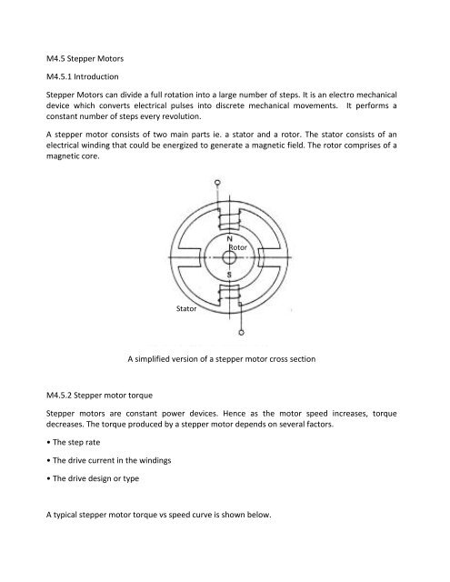
A stepper motor consists of two main parts ie. a stator and a rotor. The stator consists of an<br />
electrical winding that could be energized to generate a magnetic field. The rotor comprises of a<br />
magnetic core.<br />
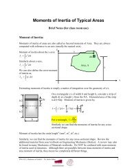
<strong>M4.5</strong>.2 <strong>Stepper</strong> motor torque<br />
A simplified version of a stepper motor cross section<br />
<strong>Stepper</strong> motors are constant power devices. Hence as the motor speed increases, torque<br />
decreases. The torque produced by a stepper motor depends on several factors.<br />
• The step rate<br />
• The drive current in the windings<br />
• The drive design or type<br />
Stator<br />
Rotor<br />
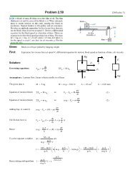
A typical stepper motor torque vs speed curve is shown below.
Pull-in torque<br />
<strong>Stepper</strong> motor torque vs speed curve<br />
This is the measure of the torque produced by a stepper motor when it is operated without an<br />
acceleration state. This is the maximum speed at which the motor <strong>can</strong> start or stop<br />
instantaneously, with a load applied, without skipping steps or synchronism. The pull in torque is<br />
basically to overcome friction and inertia.<br />
Pull-out torque<br />
The stepper motor pull-out torque is measured by accelerating the motor to the desired speed<br />
and then increasing the torque loading until the motor stalls or when it starts to skip steps. This<br />
pullout torque is calculated across a range of speeds and the stepper motor's dynamic<br />
performance curve is generated. This dynamic performance curve is useful when the motor is<br />
used for applications require accelerating and decelerating.<br />
Detent torque<br />
Electric motors using permanent magnets have a remnant position holding torque when these<br />
are not driven electrically. This detent torque is very useful for some of the applications as the<br />
motor continues to apply a torque even then the current is disconnected.
Holding torque<br />
This is the maximum torque produced when the motor is at a standstill.<br />
Maximum start rate<br />
This is the maximum no-load load speed the motor <strong>can</strong> achieve from a standing start.<br />
Maximum slew rate<br />
This is the maximum speed which the motor <strong>can</strong> achieve. This is the highest no load speed which<br />
the motor could accelerate without skipping steps.<br />
Slew Region<br />
Slew region defines the usual operating region of a stepper motor. At this region it will operate<br />
without skipping steps.<br />
<strong>M4.5</strong>.3 How a stepper motor works<br />
Polarity of windings
Modes of driving stepper motors<br />
• Full-Step Drive
• Half-Step Drive
The full step drive provides more torque as both coils are energized at the same time. When a<br />
higher resolution for step size is needed the half step drive is suitable. This corresponds to twice<br />
as many step pulses per revolution. However, the torque produced during the half step drive is<br />
less compared to that of the full step drive.<br />
<strong>M4.5</strong>.4 Winding Arrangements of stepper motors<br />
Unipolar Winding Arrangement<br />
A stepper motor with the unipolar winding arrangement<br />
Unipolar arrangement motors have an additional center-tap on each phase for a total of six lead<br />
wires. With the center-taps connected to a common voltage source, unipolar stepper motors <strong>can</strong><br />
be controlled with four identical “switches”, typically NPN or N-channel drive transistors (see<br />
figure below). In conventional full-stepping mode, one motor phase is energized at a time<br />
resulting in minimum power consumption and high positional accuracy regardless of winding<br />
imbalance. Half-stepping control alternates between energizing a single phase and two phases<br />
simultaneously resulting in an eight-step sequence which provides higher resolution, lower noise<br />
levels and less susceptibility to motor resonance.
The desired drive waveforms are illustrated in the figure below. The eight step drive sequence<br />
shown (steps 1 through 8) advances the stepper motor four full steps or eight half steps.<br />
Reversing the drive sequence (i.e., from step 8 towards 1) reverses the direction of rotation.<br />
Bipolar Winding Arrangement<br />
Half-step switching sequence for a unipolar stepper motor<br />
A stepper motor with the bipolar winding arrangement
A bipolar permanent magnet motor consists of a rotating permanent magnet surrounded by<br />
stator poles carrying the windings which is shown in the figure above. This motor uses<br />
bidirectional drive current and the motor is stepped by switching the windings in a sequence.<br />
For a motor of this type there are three possible drive sequences. The first is to energize the<br />
windings in the sequence AB/CD/BA/DC (BA means that the winding AB is energized but in the<br />
opposite sense). This sequence is known as "one phase on" full step or wave drive mode. Only<br />
one phase is energized at any given moment (see figure below).<br />
The second possibility is to energize both phases together, so that the rotor always aligns itself<br />
between two pole positions. Called "two-phase-on" full step, this mode is the normal drive<br />
sequence for a bipolar motor and gives the highest torque (figure 2 and figure 4b).<br />
The third option is to energize one phase, then two, then one, etc., so that the motor moves in<br />
half step increments. This sequence, known as half step mode, halves the effective step angle of<br />
the motor but gives a less regular torque (figure 2 and figure 4c).<br />
For rotation in the opposite direction (counter-clockwise) the same three sequences are used,<br />
except of course that the order is reserved. As shown in these diagrams the motor would have a<br />
step angle of 90°. Real motors have multiple poles to reduce the step angle to a few degrees but<br />
the number of windings and the drive sequences are unchanged.
Figure 2: “Two-phase-on” full step and half-step switching sequence for bipolar<br />
stepper motor