Software Performance Characterization of Block Cipher Structures ...
Software Performance Characterization of Block Cipher Structures ...
Software Performance Characterization of Block Cipher Structures ...

You also want an ePaper? Increase the reach of your titles
YUMPU automatically turns print PDFs into web optimized ePapers that Google loves.
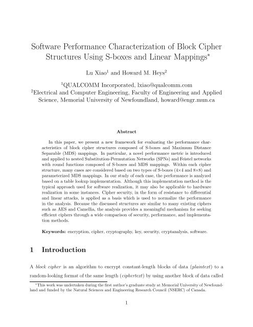
<strong>S<strong>of</strong>tware</strong> <strong>Performance</strong> <strong>Characterization</strong> <strong>of</strong> <strong>Block</strong> <strong>Cipher</strong><br />
<strong>Structures</strong> Using S-boxes and Linear Mappings ∗<br />
Lu Xiao 1 and Howard M. Heys 2<br />
1 QUALCOMM Incorporated, lxiao@qualcomm.com<br />
2 Electrical and Computer Engineering, Faculty <strong>of</strong> Engineering and Applied<br />
Science, Memorial University <strong>of</strong> Newfoundland, howard@engr.mun.ca<br />
Abstract<br />
In this paper, we present a new framework for evaluating the performance characteristics<br />
<strong>of</strong> block cipher structures composed <strong>of</strong> S-boxes and Maximum Distance<br />
Separable (MDS) mappings. In particular, a novel performance metric is introduced<br />
and applied to nested Substitution-Permutation Networks (SPNs) and Feistel networks<br />
with round functions composed <strong>of</strong> S-boxes and MDS mappings. Within each cipher<br />
structure, many cases are considered based on two types <strong>of</strong> S-boxes (4×4 and 8×8) and<br />
parameterized MDS mappings. In our study <strong>of</strong> each case, the performance is analyzed<br />
based on a table lookup implementation. Although this implementation method is the<br />
typical approach used for s<strong>of</strong>tware realization, it may also be applicable to hardware<br />
realization in some instances. <strong>Cipher</strong> security, in the form <strong>of</strong> resistance to differential<br />
and linear attacks, is applied as a basis which is used to normalize the performance<br />
in the analysis. Because the discussed structures are similar to many existing ciphers<br />
such as AES and Camellia, the analysis provides a meaningful mechanism for seeking<br />
efficient ciphers through a wide comparison <strong>of</strong> security, performance, and implementation<br />
methods.<br />
Keywords: encryption, cipher, cryptography, key, security, cryptanalysis, s<strong>of</strong>tware.<br />
1 Introduction<br />
A block cipher is an algorithm to encrypt constant-length blocks <strong>of</strong> data (plaintext) to a<br />
random-looking format <strong>of</strong> the same length (ciphertext) by using another block <strong>of</strong> data called<br />
∗ This work was undertaken during the first author’s graduate study at Memorial University <strong>of</strong> Newfoundland<br />
and funded by the Natural Sciences and Engineering Research Council (NSERC) <strong>of</strong> Canada.<br />
1
a key [1]. In a symmetric key block cipher, the same key is used for both encryption and<br />
decryption. Since decryption is computationally difficult without knowledge <strong>of</strong> the key,<br />
for secure communication applications, encrypted data can be protected from unwanted<br />
eavesdropping as long as the key is kept private to only the transmitter and receiver. A<br />
block cipher (usually referring to a symmetric key block cipher) is typically composed <strong>of</strong><br />
several rounds <strong>of</strong> simple cryptographic operations. The cipher key is expanded to a number<br />
<strong>of</strong> subkeys by a key schedule and the subkeys are mixed with data blocks in different rounds<br />
typically by bitwise eXclusive-ORs (XORs). Because <strong>of</strong> its high performance, the block<br />
cipher is now widely used in various security applications [2] such as basic data encryption<br />
in Internet protocols (IPsec and SSL/TLS), wireless communications, and digital rights<br />
management.<br />
Round 1<br />
Round 2~R-2<br />
Round R-1<br />
⋅ ⋅<br />
⋅ ⋅<br />
S-box<br />
⋅ ⋅<br />
⋅ ⋅<br />
• • •<br />
⋅ ⋅<br />
⋅ ⋅<br />
S-box<br />
⋅ ⋅<br />
⋅ ⋅<br />
⋅ ⋅<br />
S-box<br />
⋅ ⋅<br />
⋅ ⋅<br />
• • • • • •<br />
• • •<br />
⋅ ⋅<br />
Plaintext<br />
⋅ ⋅<br />
Key Mixture<br />
⋅ ⋅<br />
S-box • • • S-box<br />
⋅ ⋅<br />
⋅ ⋅<br />
Linear Transformation<br />
⋅ ⋅<br />
Key Mixture<br />
⋅ ⋅<br />
• • •<br />
S-box S-box<br />
⋅ ⋅<br />
⋅ ⋅<br />
Linear Transformation<br />
⋅ ⋅<br />
• • •<br />
Key Mixture<br />
⋅ ⋅<br />
S-box S-box<br />
⋅ ⋅<br />
⋅ ⋅<br />
Key Mixture<br />
⋅ ⋅<br />
<strong>Cipher</strong>text<br />
• • •<br />
Round R • • •<br />
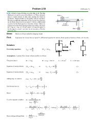
Figure 1: A Substitution-Permutation Network<br />
• • •<br />
⋅ ⋅<br />
⋅ ⋅<br />
⋅ ⋅<br />
⋅ ⋅<br />
⋅ ⋅<br />
⋅ ⋅<br />
⋅ ⋅<br />
⋅ ⋅<br />
iterated<br />
Xi-1<br />
Yi<br />
plaintext<br />
F<br />
ciphertext<br />
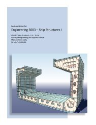
Figure 2: A Feistel Network<br />
In a symmetric key block cipher, the concepts <strong>of</strong> confusion and diffusion are vital to<br />
security [3]. The Substitution-Permutation Network (SPN) 1 and the Feistel network are two<br />
typical architectures used to achieve this [1]. During encryption using an SPN cipher, as<br />
1 For historical reasons, these ciphers are referred to as Substitution-Permutation Networks although the<br />
permutation layer is now typically replaced by an invertible linear transformation layer to improve resistance<br />
to differential and linear cryptanalysis [4].<br />
2<br />
Xi<br />
Ki
Figure 1 illustrates, typically the input data <strong>of</strong> each round is mixed with subkey bits before<br />
entering the Substitution-boxes (S-boxes). Each S-box performs a nonlinear mapping on<br />
small sub-blocks thus creating confusion in the data. An m×n S-box performs a mapping from<br />
m input bits to n output bits. The outputs <strong>of</strong> S-boxes are modified by a linear transformation<br />
whose purpose is to generate a diffusion <strong>of</strong> statistical effects in the data. The decryption is<br />
composed <strong>of</strong> the inverse linear transformations, the inverse S-boxes, and the key mixtures<br />
in reverse order. To maintain similar dataflow in encryption and decryption, SPNs typically<br />
omit the linear transformation in the last round <strong>of</strong> encryption.<br />
As the other typical architecture <strong>of</strong> block ciphers, the Feistel network has been widely<br />
used and studied. In each round i <strong>of</strong> a Feistel network as shown in Figure 2, the right<br />
half <strong>of</strong> the round input (denoted as Xi) goes through function F parameterized by subkey<br />
Ki. Also called the round function, F <strong>of</strong>ten consists <strong>of</strong> key mixture, S-boxes, and a linear<br />
transformation [1]. The output <strong>of</strong> F, denoted as Yi, is XORed bit-by-bit with the left half<br />
<strong>of</strong> the round input Xi−1. The round output is then derived by swapping Xi and Xi−1 ⊕ Yi,<br />
where “⊕” represents bitwise XOR.<br />
As the only nonlinear component in both cipher architectures, the S-box is well de-<br />
signed to meet many security requirements. Different S-boxes in a cipher can have different<br />
mappings or one mapping can be used for all S-boxes in a cipher. In many recently pro-<br />
posed block ciphers, the outputs <strong>of</strong> a layer <strong>of</strong> parallel S-boxes are passed through a linear<br />
transformation based on a Maximum Distance Separable (MDS) code [5].<br />
Recent initiatives in cryptography have focussed on the development <strong>of</strong> new block cipher<br />
standards. As the successor <strong>of</strong> the Data Encryption Standard (DES) [6], the SPN cipher<br />
Rijndael [7] was selected by the U.S. National Institute <strong>of</strong> Standards and Technology as the<br />
Advanced Encryption Standard (AES) [8] in November 2001. As a Feistel network proposed<br />
in [9], Camellia was included together with AES into the NESSIE 2 portfolio <strong>of</strong> 128-bit block<br />
ciphers in February 2003 [10]. Consequently, AES and Camellia are two important examples<br />
<strong>of</strong> ciphers that are expected to be widely used in cryptographic applications <strong>of</strong> the future.<br />
In this paper, a novel performance metric is presented which allows us to consider the<br />
2 New European Schemes for Signatures, Integrity, and Encryption<br />
3
performance <strong>of</strong> a cipher structure as the combination <strong>of</strong> security and efficiency. Many param-<br />
eterized cases <strong>of</strong> 128-bit block ciphers are studied including cases which correspond closely<br />
to recently proposed ciphers such as AES and Camellia. The security <strong>of</strong> each cipher case is<br />
evaluated by considering the resistance to differential cryptanalysis [11] and linear cryptanal-<br />
ysis [12]. The s<strong>of</strong>tware efficiency is mainly evaluated through a table-lookup implementation,<br />
where the number <strong>of</strong> table lookups is used as the time measure and the table size required is<br />
the space measure. A table-lookup implementation method is selected because it is usually<br />
efficient and such a method makes it possible to compare performance generally across differ-<br />
ent cipher configurations and different computing platforms. The efficiencies <strong>of</strong> other imple-<br />
mentations (e.g., bitslicing, xtime [7], and power-index exchange) are also briefly examined<br />
in this paper. The significance and novelty <strong>of</strong> this work is that it facilitates the performance<br />
characterization <strong>of</strong> AES, Camellia, and many other existing or prospective ciphers from a<br />
cryptographic view. Our analysis is focused on s<strong>of</strong>tware-oriented implementation on typical<br />
computer systems. However, similar techniques can be applied to hardware implementations<br />
where a table lookup method is used as the basis for the implementation.<br />
2 Background<br />
2.1 <strong>Block</strong> <strong>Cipher</strong>s<br />
AES is an SPN with a block size <strong>of</strong> 128 bits. The key size can be 128, 192, and 256 bits,<br />
which requires 10, 12, and 14 iterations <strong>of</strong> the round structure, respectively. Each round<br />
<strong>of</strong> AES consists <strong>of</strong> a layer <strong>of</strong> 16 parallel 8×8 S-boxes, a linear transformation composed<br />
<strong>of</strong> the shifting <strong>of</strong> bytes and MDS mappings, and key mixture using XORs. The ciphers<br />
SHARK [13], Square [14], Anubis [15], Khazad [16], and Hierocrypt (including Type I, Type<br />
II, and Hierocrypt-3) [17, 18] are further examples <strong>of</strong> SPNs based on 8×8 S-boxes. Serpent [19]<br />
has a simple round structure based on small 4×4 S-boxes.<br />
Camellia is an 18-round Feistel network for use with 128-bit keys or a 24-round Feistel<br />
network for use with 192- or 256-bit keys. The round function <strong>of</strong> Camellia consists <strong>of</strong> key<br />
mixture using XORs, 8 parallel 8×8 S-boxes, and a linear transformation. Camellia also<br />
4
contains input/output subkey mixtures and two logic functions every 6 rounds denoted as<br />
FL and FL −1 .<br />
2.2 Differential and Linear Attacks<br />
Differential cryptanalysis [11] and linear cryptanalysis [12] have been recognized as two <strong>of</strong> the<br />
most fundamental security threats to block ciphers. Differential attacks are chosen-plaintext<br />
attacks which exploit the statistical relation between the input difference and output differ-<br />
ence <strong>of</strong> any two plaintext-ciphertext pairs. A difference is defined to be the bitwise XOR <strong>of</strong><br />
two vectors. For example, in an SPN cipher <strong>of</strong> R rounds, an attacker hopes to find a mapping<br />
from some plaintext difference to some output difference <strong>of</strong> the (R−1)-th round, which occurs<br />
with a significant probability p. With this mapping (called a differential), the attacker can<br />
decrypt the corresponding ciphertexts one round with all possible key candidates <strong>of</strong> the last<br />
round. By checking for which key candidate the output difference <strong>of</strong> the differential holds<br />
for the calculated outputs <strong>of</strong> the (R−1)-th round most frequently, the valid key candidate<br />
<strong>of</strong> the last round can be distinguished.<br />
Linear attacks are known-plaintext attacks which exploit linear expressions (XOR sums)<br />
consisting <strong>of</strong> a subset <strong>of</strong> input bits, output bits, and key bits. If all bit variables <strong>of</strong> a linear<br />
expression are random, the probability that the linear approximation holds is 0.5 for all<br />
plaintext-ciphertext pairs associated with the same cipher key. However, based on the cipher<br />
structure, an attacker may find some linear approximations exist with a probability quite<br />
different from 0.5. A possible attacking method is to find such a linear expression consisting<br />
<strong>of</strong> bit variables <strong>of</strong> the plaintext and output <strong>of</strong> the (R−1)-th round. Then the corresponding<br />
ciphertexts are decrypted one round with all possible candidates <strong>of</strong> the last round subkey.<br />
By checking for which key candidate the linear expression holds true with a probability bias<br />
significantly different than 0.5, the attacker can distinguish the valid key candidate from<br />
others.<br />
For differential and linear cryptanalysis, once the last subkey is distinguished, it is<br />
straightforward for the attacker to use the same technique to determine key bits from the<br />
(R−1)-th round, the (R−2)-th round, etc.. To thwart these two attacks, cipher designers<br />
5
construct ciphers so that there are no large differential probabilities and there are no large<br />
biases from 0.5 for the probability that a linear expression holds. To achieve this, no highly<br />
likely characteristics should exist in the cipher. A differential characteristic <strong>of</strong> γ rounds is a<br />
sequence denoted as (∆Z0, ∆Z1, · · ·, ∆Zi, · · ·, ∆Zγ), where ∆Z0 is the input difference <strong>of</strong> the<br />
first round, ∆Zγ is the output difference <strong>of</strong> the last round, and ∆Zi is the output difference<br />
<strong>of</strong> the i-th round and also the input <strong>of</strong> the (i+1)-th round (0 < i < γ). Since any linear<br />
approximation <strong>of</strong> a data block or vector can be regarded as its inner product with a masking<br />
bit vector over GF(2), a linear characteristic is a sequence <strong>of</strong> masking values denoted as<br />
(ΓZ0, ΓZ1, · · ·, ΓZi, · · ·, ΓZγ), where ΓZ0 is the masking value for the first round input,<br />
ΓZγ is that for the last round output, and ΓZi is that for the i-th round output and also<br />
the (i+1)-th round input. An S-box is active if it is involved in the differential (respectively,<br />
linear) characteristic in a differential (respectively, linear) attack.<br />
It should be noted that differential and linear cryptanalysis are practical approximations<br />
<strong>of</strong> more powerful theoretical attacks. Also depending on the specific cipher design, it is<br />
possible for some ciphers to be more vulnerable to other attacks, such as integral attacks [7].<br />
2.3 Properties <strong>of</strong> S-boxes<br />
The properties <strong>of</strong> the S-boxes in a cipher are important in the consideration <strong>of</strong> a cipher’s<br />
security against differential and linear attacks. An m×n S-box, S, performs a mapping from<br />
an m-bit input X to an n-bit output Y . Considering all S-boxes, {Si}, in a cipher, the<br />
maximum differential probability ps is defined [11] as:<br />
ps � max<br />
i<br />
max<br />
∆X�=0,∆Y prob{Si(X) ⊕ Si(X ⊕ ∆X) = ∆Y }<br />
where “⊕” denotes a bitwise XOR and “∆X” and “∆Y ” denote bitwise XOR differences.<br />
The maximum linear probability 3 is defined [12] as:<br />
qs � max<br />
i<br />
max<br />
ΓY �=0,ΓX (2×prob{X · ΓX = Si(X) · ΓY } − 1) 2<br />
where “·” denotes a bitwise inner product and ΓX and ΓY denote masking variables. In this<br />
paper, all 4×4 S-boxes are assumed to satisfy ps, qs ≤ 2 −2 and all 8×8 S-boxes are assumed to<br />
3 The terminology used here is the same as defined in [9, 20, 21] although it should be noted that it does<br />
not represent a true probability.<br />
6
satisfy ps, qs ≤ 2 −6 . Many proposed ciphers such as Serpent, AES, Hierocrypt, and Camellia<br />
have S-boxes satisfying these requirements; others such as Anubis and Khazad have slightly<br />
higher ps and qs. The probability <strong>of</strong> a differential (respectively, linear) characteristic is<br />
upper bounded by p na<br />
s (respectively, q na<br />
s ), where na is the number <strong>of</strong> active S-boxes in the<br />
characteristic used in attacking the cipher.<br />
Note that all S-boxes <strong>of</strong> a cipher can have the same mapping as is the case in AES.<br />
Alternatively, different mappings can be chosen for the S-boxes in one round as in DES or<br />
for S-boxes in different rounds as in Serpent.<br />
2.4 MDS Mappings<br />
A linear code over Galois field GF(2 n ) is denoted as a (k, m, d)-code [5], where k is the<br />
symbol length <strong>of</strong> the encoded message, m is the symbol length <strong>of</strong> the original message, and<br />
d is the minimal symbol distance between any two encoded messages. An (k, m, d)-code is<br />
MDS if d = k −m+1. In particular, a (2m, m, m+1)-code with generation matrix G = [I|C]<br />
where C is an m×m matrix and I is an identity matrix, determines an MDS mapping from<br />
the input X to the output Y through matrix multiplication over a Galois field as follows:<br />
where<br />
X =<br />
⎛<br />
⎜<br />
⎝<br />
X0<br />
.<br />
Xm−1<br />
⎞<br />
⎛<br />
⎟ ⎜<br />
⎠ , Y = ⎝<br />
fM : X ↦→ Y = C · X (1)<br />
Y0<br />
.<br />
Ym−1<br />
⎞<br />
⎛<br />
⎟ ⎜<br />
⎠, C = ⎝<br />
Every entry in X, Y, and C is an element in GF(2 n ).<br />
C0,0 . . . C0,m−1<br />
.<br />
. .. .<br />
Cm−1,0 . . . Cm−1,m−1<br />
When an invertible linear transformation f : X ↦→ Y is used in a cipher, the avalanche<br />
effect which creates resistance to differential and linear attacks may be measured with its<br />
branch number B, which is defined [22] as:<br />
B = min{H(X)<br />
+ H(Y)}<br />
X �=0<br />
where H(X) and H(Y) denote the number <strong>of</strong> nonzero elements in X and Y, respectively. It<br />
is proved that an MDS mapping as defined in (1) has an optimal branch number B equal to<br />
m + 1.<br />
7<br />
⎞<br />
⎟<br />
⎠ .
2.5 Nested SPNs<br />
The concept <strong>of</strong> a nested SPN was first introduced in [17]. In a nested SPN, S-boxes may be<br />
viewed at different levels: each S-box at a higher level is actually a small SPN at the lower<br />
level. In this paper, we examine nested SPNs which have the following properties:<br />
• The structure contains just two levels <strong>of</strong> SPNs. A higher level S-box consists <strong>of</strong> a lower<br />
level SPN; a lower level S-box is an actual 4×4 or 8×8 S-box.<br />
• The linear transformation layers in both levels are based on MDS codes, denoted as<br />
MDSH for the higher level and MDSL for the lower level.<br />
• The subkey mixture occurs directly before each layer <strong>of</strong> actual (i.e., lower-level) S-<br />
boxes. One additional subkey mixture is used to replace the linear transformation at<br />
the end <strong>of</strong> the cipher structure. The subkey bits are mixed with data bits by XOR<br />
operations.<br />
• A “round” refers to the combination <strong>of</strong> the subkey mixture, lower-level S-box layer,<br />
and subsequent MDSL or MDSH linear transformation.<br />
As Figure 3 shows, MDSL is an MDS mapping from a (2m1, m1, m1 +1)-code over GF(2 n1 ),<br />
while MDSH is an MDS mapping from a (2m2, m2, m2+1)-code over GF(2 n2 ). The variables<br />
m1, m2, n1, and n2 represent parameter choices for a nested SPN.<br />
In the most straightforward case, the output <strong>of</strong> each S-box forms one source symbol for<br />
the MDS mapping, and each encoded symbol forms the input <strong>of</strong> a subsequent S-box at the<br />
same level. So the size <strong>of</strong> an S-box is n1 bits at the lower level and n2 bits at the higher level.<br />
This leads to n2 = n1m1. Thus, the block size <strong>of</strong> the SPN is n1m1m2. For example, the<br />
128-bit block cipher Hierocrypt (Type I) [17] is described as the iteration <strong>of</strong> such a 4-round<br />
structure where n1 = 8, n2 = 32, and m1 = m2 = 4.<br />
At each level <strong>of</strong> a nested SPN, the branch number <strong>of</strong> the MDS layer determines the<br />
minimum number <strong>of</strong> active S-boxes in differential or linear cryptanalysis. For 4 rounds <strong>of</strong><br />
a nested SPN, an active S-box at the higher level contains at least m1 + 1 active S-boxes<br />
8
1st higher level<br />
S-box (n2 bits)<br />
n1 bits<br />
S<br />
• • •<br />
MDSL<br />
S<br />
S • • • S<br />
S • • • S<br />
MDSL<br />
S • • • S<br />
• • •<br />
• • •<br />
(m2-1)-th higher level<br />
S-box (n2 bits)<br />
S • • • S<br />
S • • • S<br />
MDSH<br />
MDSL<br />
S • • • S<br />
MDSL<br />
S • • • S<br />
MDSH<br />
m2-th higher level<br />
S-box (n2 bits)<br />
S • • • S<br />
MDSL<br />
S • • • S<br />
S • • • S<br />
MDSL<br />
S • • • S<br />
n 1<br />
MDSL: based on a (2m1, m1, m1+1)-code over GF( 2 )<br />
2<br />
MDSH: based on a (2m2, m2, m2+1)-code over GF( 2 n )<br />
Figure 3: Basic 2-level Nested SPN (4 Rounds)<br />
Round 1<br />
Round 2<br />
Round 3<br />
Round 4<br />
at the lower level. Since there are at least m2 + 1 active S-boxes at the higher level, the<br />
minimum number <strong>of</strong> active lower-level S-boxes is (m1 + 1)(m2 + 1). Therefore, the security<br />
against differential and linear attacks is evaluated as the following:<br />
Theorem 1 (deduced from [13, 14, 7, 17]): With the assumption that all S-box approxi-<br />
mations involved in linear and differential cryptanalysis are independent, for 4r rounds <strong>of</strong><br />
a nested SPN the maximum differential characteristic probability (denoted by Pd) is upper<br />
bounded by p r(m1+1)(m2+1)<br />
s<br />
is upper bounded by q r(m1+1)(m2+1)<br />
s .<br />
and the maximum linear characteristic probability (denoted by Pl)<br />
To attack a cipher using differential cryptanalysis, the number <strong>of</strong> chosen plaintexts is<br />
expected to be in the order <strong>of</strong> 1/Pd. Similarly, for linear cryptanalysis, the number <strong>of</strong> known<br />
plaintexts is expected to be in the order <strong>of</strong> 1/Pl. Hence, the upper bounds <strong>of</strong> Pd and Pl<br />
provided in Theorem 1 indicate the lower bounds <strong>of</strong> required workload for attacking 4r+1<br />
rounds <strong>of</strong> the cipher based on a 4r round characteristic.<br />
The basic operations in MDS codes are multiplications and additions in finite fields.<br />
When n2 is large, operations over GF(2 n2 ) are inefficient and MDSH can be costly in com-<br />
putation. An alternative method to obtain the same branch number is to concatenate several<br />
9
parallel MDS codes over a smaller finite field. The concatenated codes may be designed to<br />
facilitate a bitslice implementation.<br />
Theorem 2 [17]: An MDS mapping defined by a (2m, m, m+1)-code over the nl-bit symbol<br />
set can be constructed by concatenating l mappings defined by a (2m, m, m+1)-code over the<br />
n-bit symbol set, where l can be any positive integer.<br />
For the example illustrated by Figure 3, the MDSH mapping is defined as a (2m2, m2, m2+<br />
1)-code over GF(2 n2 ) where n2 = m1n1. We refer to this as the basic MDSH layer. To im-<br />
prove the efficiency <strong>of</strong> the MDSH layer, instead <strong>of</strong> using the basic MDSH, according to<br />
Theorem 2 we may consider equivalent MDSH layers constructed as l parallel MDS codes<br />
with smaller field size <strong>of</strong> the form denoted as l ×(2m2, m2, m2 + 1) over GF(2 n2 ) where<br />
n2 is now the smaller field size such that ln2 = m1n1. Obviously, the basic MDSH layer<br />
corresponds to l = 1. For improved efficiency, we can let l > 1 and n2 < m1n1. For ex-<br />
ample, l = m1 and n2 = n1 is equivalent to the basic MDSH layer but is composed <strong>of</strong> l<br />
parallel (2m2, m2, m2 + 1)-codes over the smaller fields GF(2 n1 ). Hence, the general relation<br />
ln2 = m1n1 can be used to determine different cases <strong>of</strong> MDSH defined by the values <strong>of</strong> the<br />
symbol size, n2, or the number <strong>of</strong> parallel MDS mappings, l. A similar approach can also be<br />
applied to the MDSL layer. However, restrictions on values <strong>of</strong> n and m must be considered<br />
for designing a (2m, m, m + 1)-code over GF(2 n ) such that 2m ≤ 2 n +1 in order that it is<br />
possible to construct an MDS code [5].<br />
The 128-bit ciphers Square, AES, and Anubis can be regarded as the iterations <strong>of</strong> 4-<br />
round nested SPNs where n1 = n2 = 8 and m1 = m2 = 4. The parameters <strong>of</strong> Hierocrypt<br />
(Type II) are selected as n1 = 8, n2 = 4, and m1 = m2 = 4.<br />
2.6 One Class <strong>of</strong> Feistel Network<br />
Figure 4 illustrates one particular class <strong>of</strong> round function F used for Feistel networks (as<br />
shown in Figure 2). Such a round function can be regarded as an SPN <strong>of</strong> one round with<br />
a size equal to half <strong>of</strong> the cipher block size. The round function includes one layer <strong>of</strong><br />
10
S S<br />
Xi<br />
Key mixture (XOR)<br />
• • •<br />
MDS<br />
Yi<br />
S<br />
Ki<br />
Figure 4: One Class <strong>of</strong> Round Function<br />
key mixture with Ki (i.e., bitwise XOR <strong>of</strong> Xi and Ki), one layer <strong>of</strong> invertible 4 S-boxes for<br />
substitution, and an MDS mapping layer as a linear transformation. If the MDS mapping<br />
layer is constructed through concatenation <strong>of</strong> several small MDS mappings, it is necessary<br />
to include a permutation <strong>of</strong> MDS symbols in the linear transformation in order to ensure<br />
the avalanche effect.<br />
In a Feistel network whose round function has an invertible linear transformation ap-<br />
pended to a layer <strong>of</strong> S-boxes, it is proved in [21] that the number <strong>of</strong> active S-boxes in any<br />
differential or linear characteristic <strong>of</strong> 4r rounds is lower bounded by r×B + ⌊r/2⌋, where B<br />
is the branch number <strong>of</strong> the linear transformation and r is an integer. Therefore, we get:<br />
Theorem 3 (deduced from [21]): For 4r rounds <strong>of</strong> a Feistel cipher with the round function<br />
<strong>of</strong> Figure 4, the maximum differential characteristic probability Pd and maximum linear<br />
characteristic probability Pl are upper bounded by p r×B+⌊r/2⌋<br />
s<br />
and q r×B+⌊r/2⌋<br />
s , respectively.<br />
3 Methodology, Applicability, and Limitations<br />
It is hard to generally compare s<strong>of</strong>tware performance among different block ciphers. The<br />
main difficulties are: (1) each cipher has its own security margin, (2) each implementation<br />
method represents a trade<strong>of</strong>f between memory and speed, (3) the number <strong>of</strong> clock cycles<br />
required by one operation is determined by the platform, and (4) one specific instruction set<br />
4 Invertible S-boxes are used so that a bijective round function can be constructed, which achieves the<br />
given upper bounds <strong>of</strong> maximal differential and linear probabilities faster in rounds than a general round<br />
function [23].<br />
11
may facilitate some operation combinations (e.g., DSP processors can do multiplication and<br />
accumulation using one single instruction). Considering the above difficulties, in order to<br />
do a general comparison, we need to select a general and efficient method to implement all<br />
the cipher cases in this paper. Moreover, a meaningful study <strong>of</strong> the performance <strong>of</strong> ciphers<br />
should make comparisons between ciphers in consideration <strong>of</strong> a consistent security level.<br />
The methodology in this paper is summarized by the following points:<br />
• Table lookup method is selected for implementation. The number <strong>of</strong> table lookups is<br />
used to evaluate efficiency and the table size is used to evaluate memory requirement.<br />
It is assumed that the available registers in the processor are more than enough to<br />
store all the table base addresses. (In practice, it is possible to minimize the number<br />
<strong>of</strong> tables by using circulant matrices for MDS codes as is done in AES [7].)<br />
• Differential and linear cryptanalysis are used for security evaluation. More specifically,<br />
maximum differential and linear characteristic probabilities are deduced for each cipher<br />
case. Side-channel attacks are not considered because, as discussed in [24], table lookup<br />
implementation is not vulnerable to timing attacks and facilitates resistance against<br />
power attacks by s<strong>of</strong>tware balancing <strong>of</strong> the lookup address.<br />
• Security and efficiency are considered together for performance comparison. As defined<br />
in Section 4.2, a performance metric is used to show the security contribution provided<br />
by each efficiency unit in a cipher.<br />
The applicability <strong>of</strong> this methodology includes:<br />
• <strong>Cipher</strong>s using S-boxes and linear transformations, such as MDS mappings. A large<br />
set <strong>of</strong> recently proposed ciphers are covered, including SHARK, Square, AES, Anubis,<br />
Khazad, Hierocrypt, Serpent, and Camellia. Actually, although the metric in this<br />
paper is broadly applicable to any cipher that can have its security characterized on a<br />
per round basis, the analysis is most obviously applicable to SPNs and Feistel ciphers.<br />
It is particularly useful to consider these 2 classes to determine the various trade<strong>of</strong>fs<br />
in selecting cipher parameters such as S-box size and MDS field size.<br />
12
• Typical processors such as Pentium series and Alpha machines. Since parallelism in<br />
processors is not considered, the analysis cannot be directly applied to processors with<br />
parallel units such as the VLIW CPUs discussed in [25]. Because <strong>of</strong> the memory<br />
requirements <strong>of</strong> the table lookup approach, the method has limited applicability to a<br />
memory-restricted environment such as a smart card.<br />
• No limitation on MDS codes. The elements in the generation matrix can be freely<br />
selected to meet the MDS property. Some MDS codes (e.g., MixColumn in AES [7])<br />
are optimized for xtime realization, while the majority are not (e.g., Hierocrypt’s MDS<br />
mappings [17]).<br />
• No limitation on key schedule. However, it is assumed that the key schedule is done<br />
beforehand and all subkeys are stored in memory. Some ciphers can expand subkeys<br />
on the fly to save memory but require more processing time during encryption.<br />
• No limitation on the number <strong>of</strong> rounds. Many ciphers, such as AES and Camellia,<br />
require different numbers <strong>of</strong> rounds for encryption when key lengths are changed. Our<br />
metric considers the security contribution provided by each lookup, which is roughly in-<br />
dependent on the number <strong>of</strong> rounds as will be demonstrated in Section 4.2. Thus, these<br />
ciphers can be analyzed effectively and uniformly whatever key length and number <strong>of</strong><br />
rounds are selected.<br />
The limitations <strong>of</strong> this methodology are:<br />
• Although it is general and fast, the table lookup method might not always be the fastest<br />
for specific processors. Some CPUs can combine data processing instructions with<br />
shifts and rotates without a penalty, which may lead to a fast implementation using<br />
the xtime operation [7] (i.e., one-bit left shifting followed by addition with the irre-<br />
ducible polynomial) when the processor word is small. For example, in Rijndael’s AES<br />
proposal [7], the xtime method is recommended for 8-bit processors while the table<br />
lookup method is recommended for 32-bit processors.<br />
13
• The discrepancy <strong>of</strong> efficiency caused by different table sizes is ignored. A large table<br />
causes more cache misses during addressing. On the other hand, a small table needs<br />
additional bit manipulations for index preparation and output arrangement [26]. More-<br />
over, it is also difficult to model cache misses across platforms with different cache sizes<br />
and structures. The experimental results listed in Section 5 show that the effects <strong>of</strong><br />
this limitation are tolerable on the tested platforms.<br />
4 Comparison <strong>of</strong> <strong>S<strong>of</strong>tware</strong> <strong>Performance</strong><br />
In this section, we present a detailed discussion <strong>of</strong> the performance comparison based on<br />
table lookup implementations.<br />
4.1 Table Lookup Implementations<br />
The table lookup approach incorporates the S-boxes and the linear transformation into a<br />
table that is then accessed to perform both operations. This approach has been used for<br />
fast implementations <strong>of</strong> DES [27], AES [7], and Camellia [28]. Using this approach, the two<br />
cipher structures discussed in the former section can be implemented efficiently in s<strong>of</strong>tware<br />
through table lookups, logic operations (e.g., XORs), and rotations. This paper analyzes<br />
the efficiency <strong>of</strong> such fast implementations so that the memory and computational cost for<br />
a cipher case can be estimated. Independent <strong>of</strong> the targeted machine, the space complexity<br />
is evaluated as memory used for tables and the time complexity is evaluated by the number<br />
<strong>of</strong> table lookups.<br />
The table lookup approach is chosen for analysis because it is normally faster and more<br />
general than other implementation approaches. A table lookup operation involves the reading<br />
<strong>of</strong> data from memory and also encompasses other operations necessary for indexing such as<br />
rotation and masking. Although the number <strong>of</strong> clock cycles to implement different operations<br />
is machine dependent, using the number <strong>of</strong> lookups and the size <strong>of</strong> the tables is suitable for<br />
determining a rough estimate <strong>of</strong> the time and space complexity <strong>of</strong> an efficient s<strong>of</strong>tware<br />
implementation.<br />
14
In s<strong>of</strong>tware, regardless <strong>of</strong> the implementation approach, the S-box layer is typically done<br />
by table lookups. An MDS mapping based on a (2m, m, m + 1)-code conceptually performs<br />
a matrix multiplication over a Galois field, which requires m 2 modular multiplications and<br />
m(m −1) XORs on words that are size <strong>of</strong> Galois field elements. To bypass costly multiplica-<br />
tions, we enlarge the S-box table such that the MDS mapping work is included in the table<br />
lookups. This is the essence <strong>of</strong> the table lookup implementation. According to the size <strong>of</strong><br />
the S-boxes and the type <strong>of</strong> MDS mappings, any cipher case may select appropriate methods<br />
as follows to generate lookup tables.<br />
4.1.1 Cases with 8×8 S-boxes<br />
The dataflow <strong>of</strong> a round in these cases involves the keyed input entering 8×8 S-boxes followed<br />
by l mappings based on a (2m, m, m + 1)-code over GF(2 8 ). (The case <strong>of</strong> two concatenated<br />
mappings over GF(2 4 ) will be discussed later.) To represent the operations mathematically,<br />
we denote the input, output, subkey, and MDS generation matrix as {Ai}, {Ei}, {Ki}, and<br />
{Ci,j}, respectively, each containing 8-bit elements. Thus, the key mixture, S-box layer, and<br />
MDS mapping can be expressed together as:<br />
⎛<br />
⎜<br />
⎝<br />
E0<br />
E1<br />
.<br />
⎞<br />
⎟<br />
⎠ =<br />
⎛<br />
⎜<br />
⎝<br />
C0,0<br />
C1,0<br />
.<br />
C0,1<br />
C1,1<br />
.<br />
. . .<br />
. . .<br />
. ..<br />
C0,m−1<br />
C1,m−1<br />
.<br />
Em−1<br />
Cm−1,0 Cm−1,1 . . . Cm−1,m−1<br />
⎞<br />
⎛<br />
⎟<br />
⎠ ×<br />
⎜<br />
⎝<br />
Denoting the keyed input as Bi = Ai ⊕ Ki, (2) is equivalent to:<br />
⎛ ⎞ ⎛ ⎞<br />
⎛<br />
⎜<br />
⎝<br />
E0<br />
E1<br />
.<br />
Em−1<br />
⎟<br />
⎠ =<br />
⎜<br />
⎝<br />
C0,0<br />
C1,0<br />
.<br />
Cm−1,0<br />
⎟<br />
⎠ × S(B0)<br />
⎜<br />
⊕ · · · ⊕ ⎜<br />
⎝<br />
Hence, we may generate m tables as the following:<br />
⎛<br />
⎜<br />
Tj[·] = ⎜<br />
⎝<br />
C0,j × S(·)<br />
C1,j × S(·)<br />
.<br />
Cm−1,j × S(·)<br />
⎞<br />
⎟<br />
⎠<br />
15<br />
C0,m−1<br />
C1,m−1<br />
.<br />
Cm−1,m−1<br />
S(A0 ⊕ K0)<br />
S(A1 ⊕ K1)<br />
.<br />
S(Am−1 ⊕ Km−1)<br />
⎞<br />
⎞<br />
⎟ . (2)<br />
⎠<br />
⎟<br />
⎠ × S(Bm−1). (3)<br />
(4)
where 0≤j ≤m−1. The output <strong>of</strong> several S-boxes followed by the MDS mapping may then<br />
be generated using: ⎛<br />
⎜<br />
⎝<br />
E0<br />
E1<br />
.<br />
Em−1<br />
⎞<br />
⎟<br />
⎠ = T0[B0] ⊕ · · · ⊕ Tm−1[Bm−1]. (5)<br />
Each fetch from the table Tj[·] accepts an 8-bit input as the index and produces an<br />
8m-bit output from the indexed entry. It takes 256m 2 bytes <strong>of</strong> memory to store these m<br />
tables. Given a processor with a word size <strong>of</strong> w bits, implementation <strong>of</strong> (5) needs m⌈8m/w⌉<br />
lookups and (m−1)⌈8m/w⌉ XORs. In cases where the word size w is larger than the size<br />
<strong>of</strong> a table index, the preparation <strong>of</strong> a table lookup input will generally need a rotation and<br />
masking (bitwise AND) within a word.<br />
When the size <strong>of</strong> an MDS field is smaller than the size <strong>of</strong> the S-boxes, we can consider an<br />
MDS mapping layer <strong>of</strong> more than one MDS mapping (i.e., the adjacent S-box output bits may<br />
pass through different mappings). The table Tj[·] is then established through concatenation.<br />
Each entry <strong>of</strong> Tj[·] consists <strong>of</strong> concatenated results from different MDS mappings. The result<br />
from one mapping corresponds to a specific subset <strong>of</strong> the table lookup output. For example,<br />
considering 8×8 S-boxes followed by 2×(2m, m, m + 1) over GF(2 4 ), each coefficient Cij in<br />
(2) can be regarded as concatenation <strong>of</strong> two 4-bit coefficients C ′<br />
ij<br />
and C′′<br />
ij<br />
from two MDS<br />
mappings, so that Cij = C ′<br />
ij || C′′ ij , where “ || ” denotes concatenation. Then we generate m<br />
tables as:<br />
⎛<br />
⎜<br />
Tj[·] = ⎜<br />
⎝<br />
C ′<br />
0,j ×S ′<br />
C ′<br />
1,j ×S ′<br />
C ′<br />
m−1,j ×S′<br />
(·) || C ′′<br />
0,j ×S ′′<br />
(·) || C ′′<br />
1,j ×S ′′<br />
.<br />
(·)<br />
(·)<br />
(·) || C ′′<br />
m−1,j ×S′′<br />
where 0 ≤ j ≤ m −1, S ′<br />
(·) and S ′′<br />
(·) represent 4 output bits <strong>of</strong> an S-box, and S(·) =<br />
S ′<br />
(·)|| S ′′<br />
(·). When these concatenated tables {Tj[·]} are used in (5), the size <strong>of</strong> tables and<br />
the number <strong>of</strong> lookups and XORs are the same as for the tables required in (4).<br />
4.1.2 Cases with 4×4 S-boxes<br />
In constrained environments such as smart cards, cipher cases using 4×4 S-boxes cost much<br />
less memory for table storage than those using 8×8 S-boxes. We can use the same method<br />
16<br />
(·)<br />
⎞<br />
⎟<br />
⎠<br />
(6)
described by (3) and (5) to generate a set <strong>of</strong> small tables. Since the variables Bi and Ei in<br />
(3) and (5) are now 4 bits, each fetch from the table Tj[·] accepts a 4-bit input as the index<br />
and produces a 4m-bit output from the indexed entry. It takes 8m 2 bytes <strong>of</strong> memory to<br />
store these m tables since each table requires 16·m·4/8 = 8m bytes. Such an implementation<br />
needs m⌈4m/w⌉ lookups and (m−1)⌈4m/w⌉ XORs.<br />
When memory is not constrained, a modified method can be used to reduce the number<br />
<strong>of</strong> table lookups by a factor <strong>of</strong> 2. To implement a cipher case with 4×4 S-boxes, each table<br />
Tj[·] in (5) has an index <strong>of</strong> 4 bits. We can combine two tables into one, represented by T ′ j,<br />
whose index is 8 bits. As a result, (5) is transformed to:<br />
⎛ ⎞<br />
⎜<br />
⎝<br />
E0<br />
E1<br />
.<br />
Em−1<br />
⎟<br />
⎠ = T ′ 0[B0|| B1] ⊕ · · · ⊕ T ′ m<br />
2 −1[Bm−2|| Bm−1]. (7)<br />
where Bi and Ei are representing 4-bit values. For each 8-bit input X|| Y composed <strong>of</strong> 2<br />
concatenated 4-bit values, X and Y , the table performs:<br />
T ′ j[X|| Y ] = T2j[X] ⊕ T2j+1[Y ]<br />
where 0 ≤ j ≤ m/2 − 1. It takes 64m 2 bytes <strong>of</strong> memory to store these m/2 tables. The<br />
implementation <strong>of</strong> (7) needs (m/2)⌈4m/w⌉ lookups and (m/2−1)⌈4m/w⌉ XORs.<br />
The method expressed by (7) should also be chosen for the cases where the symbol<br />
length <strong>of</strong> an MDS mapping is larger than the S-box size. For example, the inputs <strong>of</strong> two<br />
adjacent 4×4 S-boxes followed by an MDS mapping over GF(2 8 ) have to be combined as an<br />
8-bit index to a table <strong>of</strong> 256 elements.<br />
4.2 Comparison Based on Table Lookup Implementations<br />
4.2.1 Time <strong>Performance</strong> Metric<br />
In s<strong>of</strong>tware, the memory used for table storage is independent <strong>of</strong> the number <strong>of</strong> rounds. To<br />
compare the time used for a given cipher to achieve a certain amount <strong>of</strong> security, we define<br />
the time performance measure η(w) with respect to differential and linear attacks, where w<br />
17
is the processor word size:<br />
η(w) =<br />
log 2 1/P<br />
(# <strong>of</strong> rounds) × (# <strong>of</strong> table lookups per round)<br />
. (8)<br />
The numerator <strong>of</strong> (8) is a function <strong>of</strong> cipher structure while the denominator is a function<br />
<strong>of</strong> both cipher structure and word size w. The value <strong>of</strong> log 2 1/P indicates the security <strong>of</strong><br />
the cipher for a specified number <strong>of</strong> rounds, where we use a heuristic approach to determine<br />
resistance to differential and linear cryptanalysis. For differential cryptanalysis, the number<br />
<strong>of</strong> chosen plaintexts to attack a cipher is expected to be in the order <strong>of</strong> 1/P, where P is<br />
the maximum differential characteristic probability Pd determined by Theorems 1 and 3; the<br />
number <strong>of</strong> known plaintexts required by linear cryptanalysis is expected to be in the order<br />
<strong>of</strong> 1/P, where P is the maximum linear characteristic probability Pl <strong>of</strong> the cipher. For the<br />
nested SPNs and Feistel networks discussed in Section 2, log 2 1/P is a linear function <strong>of</strong> the<br />
number <strong>of</strong> rounds for both differential and linear cryptanalysis. Therefore, the value <strong>of</strong> η(w)<br />
indicates how much security is expected to be obtained within a unit running time (i.e., time<br />
for one table lookup), regardless <strong>of</strong> the number <strong>of</strong> rounds in a cipher.<br />
Note that one table lookup has associated with it the setup <strong>of</strong> an index (e.g., one<br />
rotation and one masking operation) and a post-lookup XOR. Among these operations, the<br />
table lookup would normally require the most clock cycles in most processors. Hence, we<br />
use the table lookups as a barometer <strong>of</strong> the number <strong>of</strong> operations required to implement the<br />
cipher.<br />
4.2.2 Comparison <strong>of</strong> Nested SPNs<br />
A set <strong>of</strong> nested SPNs can be generated with appropriate configurations <strong>of</strong> parameterized<br />
MDSL, MDSH, and S-boxes. As Theorem 2 illustrates, the MDS mapping defined over a<br />
large Galois field can be simplified using several mappings in a smaller Galois field. Table 1<br />
lists the cases <strong>of</strong> nested SPNs in 12 categories (labelled as N1 to N12) defined by the S-boxes<br />
and MDSL. Thus, the cases within a category only differ in the simplification <strong>of</strong> MDSH.<br />
Each case can be regarded as 4r rounds <strong>of</strong> a 128-bit cipher where r is an integer, except that<br />
no particular key schedule has been defined. Due to the difficulty <strong>of</strong> finding optimized MDS<br />
18
Table 1: 128-bit Nested SPNs <strong>of</strong> 4r Rounds<br />
Case S-box MDSL : MDSH : Pd, Pl<br />
size l1×(2m1, m1, m1+1) over GF(2 n1) l2×(2m2, m2, m2+1) over GF(2 n2)<br />
N1-a 8×8 8×(4, 2, 3) over GF(2 8 ) 2×(16, 8, 9) over GF(2 8 ) 2 −162r<br />
N1-b 4×(16, 8, 9) over GF(2 4 )<br />
N2-a 8×8 16×(4, 2, 3) over GF(2 4 ) 2×(16, 8, 9) over GF(2 8 ) 2 −162r<br />
N2-b 4×(16, 8, 9) over GF(2 4 )<br />
N3-a 8×8 32×(4, 2, 3) over GF(2 2 ) 2×(16, 8, 9) over GF(2 8 ) 2 −162r<br />
N3-b 4×(16, 8, 9) over GF(2 4 )<br />
N4-a 8×8 4×(8, 4, 5) over GF(2 8 ) 4×(8, 4, 5) over GF(2 8 ) 2 −150r<br />
N4-b 8×(8, 4, 5) over GF(2 4 )<br />
N5-a 8×8 8×(8, 4, 5) over GF(2 4 ) 4×(8, 4, 5) over GF(2 8 ) 2 −150r<br />
N5-b 8×(8, 4, 5) over GF(2 4 )<br />
N6-a 8×8 2×(16, 8, 9) over GF(2 8 ) 8×(4, 2, 3) over GF(2 8 ) 2 −162r<br />
N6-b 16×(4, 2, 3) over GF(2 4 )<br />
N7-a 8×8 4×(16, 8, 9) over GF(2 4 ) 8×(4, 2, 3) over GF(2 8 ) 2 −162r<br />
N7-b 16×(4, 2, 3) over GF(2 4 )<br />
N7-c 32×(4, 2, 3) over GF(2 2 )<br />
N8 8×8 1×(32, 16, 17) over GF(2 8 ) same as MDSL 2 −204r<br />
N9 4×4 16×(4, 2, 3) over GF(2 4 ) 1×(32, 16, 17) over GF(2 8 ) 2 −102r<br />
N10 4×4 32×(4, 2, 3) over GF(2 2 ) 1×(32, 16, 17) over GF(2 8 ) 2 −102r<br />
N11-a 4×4 8×(8, 4, 5) over GF(2 4 ) 2×(16, 8, 9) over GF(2 8 ) 2 −90r<br />
N11-b 4×(16, 8, 9) over GF(2 4 )<br />
N12-a 4×4 4×(16, 8, 9) over GF(2 4 ) 4×(8, 4, 5) over GF(2 8 ) 2 −90r<br />
N12-b 8×(8, 4, 5) over GF(2 4 )<br />
mappings, the cases with a Galois field larger than GF(2 8 ) are not considered. The values<br />
<strong>of</strong> Pd and Pl represent the differential and linear characteristic probabilities for 4r rounds<br />
evaluated by Theorem 1 and used as P in (8) to determine η(w).<br />
In relation to real ciphers, case N4-a includes Square, AES, and Anubis. Type II <strong>of</strong><br />
Hierocrypt belongs to case N4-b with a simplified MDSH over GF(2 4 ). Similar to SHARK<br />
and Khazad, case N8 is a one-level SPN. However, SHARK and Khazad are 64-bit ciphers<br />
because their MDS mappings are based on a (16, 8, 9)-code over GF(2 8 ).<br />
Table 2 lists the table size (i.e., the sum <strong>of</strong> sizes <strong>of</strong> tables required for MDSL and MDSH<br />
rounds) and the number <strong>of</strong> table lookups for 4 rounds for each cipher case. The table sizes<br />
shown represent a minimum requirement and can only be achieved when an S-box does not<br />
differ from the corresponding S-box in another MDS mapping in the same layer (although<br />
19
Table 2: <strong>S<strong>of</strong>tware</strong> <strong>Performance</strong> <strong>of</strong> 128-bit Nested SPNs<br />
# <strong>of</strong> table lookups<br />
Case Table size per 4 rounds η (8) η (32) η (64)<br />
(KBytes) 8-bit 32-bit 64-bit<br />
N1-a,b 17 320 96 64 0.51 1.69 2.53<br />
N2-a,b 17 320 96 64 0.51 1.69 2.53<br />
N3-a,b 17 320 96 64 0.51 1.69 2.53<br />
N4-a,b 8 † 256 64 64 0.59 2.34 2.34<br />
N5-a,b 8 † 256 64 64 0.59 2.34 2.34<br />
N6-a,b 17 320 96 64 0.51 1.69 2.53<br />
N7-a,b,c 17 320 96 64 0.51 1.69 2.53<br />
N8 64 1024 256 128 0.20 0.80 1.59<br />
N9 64.03125 576 192 128 0.18 0.53 0.80<br />
N10 64.03125 576 192 128 0.18 0.53 0.80<br />
N11-a 16.125 384 128 96 0.23 0.70 0.94<br />
N11-b 0.625 384 128 128 0.23 0.70 0.70<br />
N12-a 4.5 384 96 96 0.23 0.94 0.94<br />
N12-b 0.625 384 128 128 0.23 0.70 0.70<br />
† : By use <strong>of</strong> the same mapping in MDSL and MDSH, half <strong>of</strong> the table size can be saved.<br />
S-boxes may be different within the domain <strong>of</strong> one MDS mapping). As a result, only one<br />
table as in (5) is required for each <strong>of</strong> the MDSL and MDSH layers.<br />
For each case using 4×4 S-boxes, the tables with 4-bit indices are created as shown in (5)<br />
or (6) when the MDS mapping is chosen over GF(2 4 ) or GF(2 2 ), respectively. However, as<br />
explained in Section 4.1.2, the performance can be improved by using 8-bit indices in the<br />
lookup as in (7) at the expense <strong>of</strong> more memory. For example, case N11-b can be implemented<br />
using 8-bit indices thereby doubling the efficiency but requiring 8 times the memory to store<br />
the lookup tables for both the MDSL and MDSH rounds. When GF(2 8 ) is chosen for the<br />
MDS mapping, the length <strong>of</strong> table indices has to be 8 bits. The number <strong>of</strong> table lookups is<br />
used in the calculation <strong>of</strong> the denominator in (8).<br />
The table also includes the performance η(w) for each case. The implementation perfor-<br />
mance on three types <strong>of</strong> processors (i.e., w = 8, 32, 64) are considered. The implementation<br />
on an 8-bit processor is suitable for smart cards, where the memory size is constrained.<br />
The implementations on 32-bit and 64-bit processors are suitable for applications on general<br />
purpose computers and workstations. The values <strong>of</strong> η(w) are also presented in Figure 5. By<br />
comparing these measures, it is possible to distinguish the cases which are more efficient in<br />
20
<strong>Performance</strong> Measures<br />
m1, n1,<br />
m2, n2<br />
3<br />
2.5<br />
2<br />
1.5<br />
1<br />
0.5<br />
0<br />
N1<br />
2, 8,<br />
8, 8/4<br />
N2<br />
2, 4,<br />
8, 8/4<br />
N3<br />
2, 2,<br />
8, 8/4<br />
N4<br />
4, 8,<br />
4, 8/4<br />
N5<br />
4, 4,<br />
4, 8/4<br />
N6<br />
N7<br />
N8<br />
8, 8, 8,4,8, 16, 8,<br />
4, 8/4 8/4/2 16, 8<br />
N9<br />
N10<br />
2, 4,<br />
16, 8<br />
2, 2,<br />
16, 8<br />
N11-a<br />
4, 4,<br />
8, 8<br />
η (8)<br />
η (32)<br />
η (64)<br />
N11-b<br />
4, 4,<br />
8, 4<br />
8 x 8 S-boxes 4 x 4 S-boxes<br />
Figure 5: <strong>S<strong>of</strong>tware</strong> <strong>Performance</strong> Comparison <strong>of</strong> Nested SPNs<br />
s<strong>of</strong>tware and the following general conclusions can be made:<br />
• The implementation performance is improved when the word size <strong>of</strong> the processor<br />
increases, although in some cases there is no difference in the performance on a 32-bit<br />
or 64-bit processor.<br />
• The cases with larger S-boxes (N1, · · ·, N8) have better performance but cost more<br />
memory to store the lookup tables.<br />
• The cases with the same S-box size (N1, · · ·, N8 and N9, · · ·, N12) share similar<br />
performance although their memory requirements can vary significantly (as shown in<br />
Table 2).<br />
• Cases N4 and N5 have the best, or close to the best, performance for all word sizes.<br />
4.2.3 Comparison <strong>of</strong> Feistel Networks<br />
The Feistel network discussed in this section is limited to the class described in Section 2.4,<br />
which has an SPN-like round function. To construct a typical 128-bit cipher, such a Feistel<br />
network has a 64-bit round function which contains sixteen 4×4 or eight 8×8 parallel S-boxes<br />
followed by an MDS mapping layer. As listed in Table 3, six categories (labelled as F1 to<br />
F6) <strong>of</strong> these 128-bit Feistel networks can be generated. To ensure a good avalanche effect, an<br />
21<br />
N12-a<br />
8, 4,<br />
4, 8<br />
N12-b<br />
8, 4,<br />
4, 4
appropriate fixed permutation <strong>of</strong> MDS symbols after the MDS mapping is expected, which<br />
may cost a small amount <strong>of</strong> additional processing time. The cases <strong>of</strong> the same category in<br />
Table 3 only differ in the simplification <strong>of</strong> the MDS mapping. The performance comparison<br />
details are given in Table 4, where table lookups use 4-bit indices when 4×4 S-boxes are used<br />
in a cipher case. A summary <strong>of</strong> the performance measure η(w) is also illustrated in Figure 6.<br />
The following conclusions can be drawn:<br />
• An MDS mapping that has a large branch number (i.e., m+1) results in good perfor-<br />
mance for implementations on computers supporting a large word size (e.g., comparing<br />
η(8) and η(64) in cases F3-a and F3-b).<br />
• Although they require more memory, the cases with 8×8 S-boxes demonstrate higher<br />
performance.<br />
• For the cases with 4×4 S-boxes, we can trade<strong>of</strong>f memory and time requirements by<br />
choosing the element size <strong>of</strong> the MDS mapping. Using small Galois fields for the<br />
MDS codes, cases F4-b, F4-c, and F5-b can be used for some memory-constrained<br />
applications. However, their performance is not as high as the counterparts using large<br />
Galois fields (e.g., F4-a and F5-a) for a word size larger than 8.<br />
• Compared with nested SPN networks, the Feistel networks discussed here need less<br />
memory but result in a lower performance.<br />
Camellia uses 8×8 S-boxes and a linear transformation which is not MDS-based with<br />
branch number 5. (An MDS-based linear transformation would have a branch number <strong>of</strong> 9.)<br />
Hence, a simplified Camellia structure (without FL/FL −1 functions) produces a security<br />
level equivalent to F2-a,b in Table 3. A fast Camellia implementation using table lookups<br />
was introduced in [28], which incorporates the linear transformation and S-boxes into several<br />
tables with 8-bit indices and 64-bit entries. In this method, a simplified Camellia has the<br />
equivalent number <strong>of</strong> table lookups to 18-round F3-a,b. As a result, Camellia uses tables<br />
as large as F3-a,b, while its performance is lower than both F2-a,b and F3-a,b on 32-bit<br />
processors and equal to F2-a,b but lower than F3-a,b on 64-bit processors.<br />
22
Table 3: 128-bit Feistel Networks <strong>of</strong> 4r Rounds<br />
Case S-box MDS Pd, Pl<br />
size l×(2m, m, m+1) over GF(2 n )<br />
F1-a 8×8 4×(4, 2, 3) over GF(28 )<br />
r<br />
−6(3r+⌊ 2 2 ⌋)<br />
F1-b 8×(4, 2, 3) over GF(24 )<br />
F1-c 8×(4, 2, 3) over GF(22 )<br />
F2-a 8×8 2×(8, 4, 5) over GF(28 ) 2<br />
F2-b 4×(8, 4, 5) over GF(24 )<br />
F3-a 8×8 1×(16, 8, 9) over GF(28 ) 2<br />
F3-b 2×(16, 8, 9) over GF(24 )<br />
F4-a 4×4 4×(4, 2, 3) over GF(28 ) 2<br />
F4-b 8×(4, 2, 3) over GF(2 4 )<br />
F4-c 16×(4, 2, 3) over GF(2 2 )<br />
F5-a 4×4 2×(8, 4, 5) over GF(28 ) 2<br />
F5-b 4×(8, 4, 5) over GF(24 )<br />
F6-a 4×4 1×(16, 8, 9) over GF(28 ) 2<br />
F6-b 2×(16, 8, 9) over GF(24 )<br />
r<br />
−6(5r+⌊ 2 ⌋)<br />
r<br />
−6(9r+⌊ 2 ⌋)<br />
r<br />
−2(3r+⌊ 2 ⌋)<br />
r<br />
−2(5r+⌊ 2 ⌋)<br />
r<br />
−2(9r+⌊ 2 ⌋)<br />
Table 4: <strong>S<strong>of</strong>tware</strong> <strong>Performance</strong> <strong>of</strong> 128-bit Feistel Networks<br />
# <strong>of</strong> table lookups<br />
Case Table size per round η (8) η (32) η (64)<br />
(KBytes) 8-bit 32-bit 64-bit<br />
F1-a,b,c 1 16 8 8 0.33 0.66 0.66<br />
F2-a,b 4 32 8 8 0.26 1.03 1.03<br />
F3-a,b 16 64 16 8 0.22 0.89 1.78<br />
F4-a 1 16 8 8 0.11 0.22 0.22<br />
F4-b,c 0.03125 16 16 16 0.11 0.11 0.11<br />
F5-a 4 32 8 8 0.09 0.34 0.34<br />
F5-b 0.125 32 16 16 0.09 0.17 0.17<br />
F6-a 16 64 16 8 0.07 0.30 0.59<br />
F6-b 0.5 64 16 16 0.07 0.30 0.30<br />
5 Experimental Results<br />
The performance comparison above is based on the assumption that the number <strong>of</strong> lookups<br />
is a good time measure for table lookup implementations. We implemented typical SPN<br />
cipher cases from Table 3 in “C” and determined the throughput for each implementation<br />
on a 933MHz Intel Pentium III computer and a 2GHz Pentium 4 computer, respectively.<br />
The codes are compiled using the MS Visual C++ 6.0 compiler and optimized for speed<br />
during compilation. It is expected that the throughput will vary inversely to the number <strong>of</strong><br />
23
<strong>Performance</strong> Measures<br />
m,<br />
n<br />
2<br />
1.8<br />
1.6<br />
1.4<br />
1.2<br />
1<br />
0.8<br />
0.6<br />
0.4<br />
0.2<br />
0<br />
F1<br />
2,<br />
8/4/2<br />
F2<br />
4,<br />
8/4<br />
F3<br />
8,<br />
8/4<br />
F4-a<br />
2,<br />
8<br />
F4-b,c<br />
2,<br />
4/2<br />
F5-a<br />
F5-b<br />
8 x 8 S-boxes 4 x 4 S-boxes<br />
η (8)<br />
η (32)<br />
η (64)<br />
Figure 6: <strong>S<strong>of</strong>tware</strong> <strong>Performance</strong> Comparison <strong>of</strong> Feistel Networks<br />
lookups, considering throughput to be defined as:<br />
throughput =<br />
4,<br />
8<br />
4,<br />
4<br />
F6-a<br />
block length<br />
processing time for each block .<br />
To mitigate the effect <strong>of</strong> the multitasking operating system, we only calculated the clocks<br />
used for the test process, which repeated encrypting test vectors for millions <strong>of</strong> times. During<br />
the experiments, all unnecessary tasks were removed as much as possible.<br />
When the table index is 8 bits, the byte permutation after the lookup operations (e.g.,<br />
the concatenation <strong>of</strong> parallel MDS mappings discussed in Theorem 2) can be easily done<br />
by reordering the inputs <strong>of</strong> table lookups next round. When the table index is 4 bits as in<br />
N11-b, bit manipulation within bytes costs more processing time. This cost partly decreases<br />
the advantage <strong>of</strong> using small tables (624 bytes), which can be easily cached during the<br />
program runs. Compared with N11-b, N8 requires a much larger table size (64 KB), which<br />
causes more cache misses and results in a throughput lower than expected. Even so, as<br />
shown in Figure 7, the expected trend <strong>of</strong> throughputs evaluated by the number <strong>of</strong> lookups in<br />
total can still be clearly observed in the implementations. The bottom two rows <strong>of</strong> Table 5<br />
list the results <strong>of</strong> our 10-round AES implementation and reference code in ANSI C2.0 [29],<br />
respectively. The AES implementation uses 4 tables as defined in (4).<br />
Table 6 lists the experimental throughput results for AES and Camellia on two 64-bit<br />
24<br />
8,<br />
8<br />
F6-b<br />
8,<br />
4
Table 5: Experimental Results <strong>of</strong> 32-bit Implementations <strong>of</strong> Nested SPNs<br />
Case # <strong>of</strong> Throughput (Mbps) # <strong>of</strong> lookups Comments<br />
rounds Pentium III Pentium 4 (4 rounds)<br />
N1-a 32 45.65 77.42 96 similar to N2, N3, N6, N7<br />
N4-a 32 60.86 105.2 64 similar to 32-round AES<br />
N8 32 17.02 22.83 256 with uniform round<br />
N11-b 32 36.21 74.49 128 similar to N12-b<br />
N4-a 10 155.9 262.5 64 10-round AES (our code)<br />
N4-a 10 120.6 182.6 64 reference AES code<br />
Througput (Mbps)<br />
300<br />
250<br />
200<br />
150<br />
100<br />
50<br />
0<br />
32-Round<br />
N1-a<br />
Pentium III<br />
Pentium 4<br />
C/(# lookups)<br />
32-Round<br />
N4-a<br />
32-Round<br />
N8<br />
32-Round<br />
N11-b<br />
Figure 7: Comparison <strong>of</strong> Throughputs<br />
(C: a constant, which is set to 40,000 here)<br />
10-Round<br />
AES<br />
processors. The GNU C++ compiler is used on a 600 MHz Alpha processor (COMPAQ<br />
AlphaServer DS10, Tru64 Unix V5.1) while the SUN Workshop C++ Compiler is used on<br />
a 500 MHz UltraSPARC IIe processor (SUN Blade 100 workstation, SUN OS V5.8). Both<br />
computers have a similar 2-level cache architecture [30], where L1 cache is built in the<br />
processor and divided equally for instruction and data. The AlphaServer has 128 KB L1<br />
cache and 2 MB L2 cache; the UltraSPARC IIe has 32 KB L1 cache and 256 KB L2 cache.<br />
All implementations are optimized during compilation using the “-O2” option 5 . The<br />
32-bit implementations <strong>of</strong> AES and Camellia are tested on the two machines by using 32-bit<br />
data type arrays to store lookup tables and 32-bit operations for XORs.<br />
5 “-O2” turns on all optimization flags specified by “-O”. Only loop unrolling and function inlining are<br />
not included.<br />
25
Table 6: Experimental Results <strong>of</strong> Two Real <strong>Cipher</strong>s<br />
Throughput (Mbps)<br />
<strong>Cipher</strong> Alpha processor UltraSPARC IIe # <strong>of</strong> lookups<br />
(128KB L1 Cache) (32KB L1 Cache)<br />
AES 55.3 (32.7 † ) 69.9 (39.4 † ) 160<br />
(10 rounds, 32-bit)<br />
Simplified Camellia 72.5 (20.1 † ) 29.0 (14.8 † ) 288<br />
(18 rounds, 32-bit)<br />
Simplified Camellia 87.3 (35.2 † ) 58.2 (31.4 † ) 144<br />
(18 rounds, 64-bit)<br />
† : throughput without optimization during compilation<br />
On the Alpha processor, the throughput and the inverse <strong>of</strong> estimated number <strong>of</strong> lookups<br />
follow the same trend before optimization. After optimization, the 32-bit Camellia imple-<br />
mentation is largely improved and close to its 64-bit implementation. With the smallest<br />
number <strong>of</strong> lookups, the 64-bit simplified Camellia is still fastest after optimization. On the<br />
UltraSPARC IIe processor, the 32-bit and 64-bit Camellia implementations follow the ex-<br />
pected trend nicely. The L1 cache in the UltraSPARC IIe processor has a limited size <strong>of</strong><br />
which only half (16 KB) is used to cache data for all running processes. Therefore, the small<br />
table size <strong>of</strong> AES (4 KB) results in a throughput higher than expected in comparison to<br />
Camellia, which, with the larger table size <strong>of</strong> 16 KB, can be expected to experience more<br />
cache misses.<br />
It should be noted that the s<strong>of</strong>tware comparison <strong>of</strong> Table 6 is purely based on s<strong>of</strong>tware<br />
throughput. When security is considered simultaneously as shown in Figures 5 and 6, AES<br />
has a higher performance (as a typical SPN corresponding to N4-a) than Camellia. This<br />
reflects that fact that the Camellia cipher has a lower security margin than the AES cipher.<br />
6 Alternative Implementations<br />
Besides the table lookup approach, a block cipher can be implemented in other ways based<br />
on its structure. We briefly discuss these alternatives without a full exposé <strong>of</strong> their char-<br />
acterization because they apply to specialized circumstances rather than having general<br />
application.<br />
26
6.1 Bitslice Implementations<br />
For some cipher cases, a bitslice s<strong>of</strong>tware implementation derived from the gate level circuit<br />
may be more efficient in parallelized applications [31]. A bitslice design is suitable for the<br />
cases whose synthesized circuits are compact. A w-bit processor can be regarded as w<br />
bit-processors in parallel. The gate level network circuit is described with instructions in<br />
s<strong>of</strong>tware. Each bit in hardware corresponds to a word in s<strong>of</strong>tware and each word is the<br />
concatenation <strong>of</strong> bits belonging to w separate blocks. Given enough registers in a processor,<br />
the memory requirement is negligible since no table lookups are necessary. Typically, the<br />
bitslice technique can be applied in three ways:<br />
(a) Parallel blocks: This is the classic bitslice implementation. A total <strong>of</strong> w plaintext blocks<br />
are reorganized so that the bits at the same bit positions <strong>of</strong> different original blocks are<br />
now collected in one register. The number <strong>of</strong> registers required to store these blocks is<br />
equal to the block size <strong>of</strong> the cipher. Then, all registers are used as signals to a gate<br />
network deduced from a hardware implementation. The output signals, w bits each,<br />
are converted to their original format as w ciphertext blocks. Whether a cipher case<br />
discussed in this paper is suitable for bitslice implementation can be determined from<br />
its space performance value ηs in hardware, which was investigated in [32]. When ηs is<br />
high, a compact gate network can be used. The gate count <strong>of</strong> the circuit determines the<br />
number <strong>of</strong> instructions used in the bitslice s<strong>of</strong>tware. Thus, a high ηs indicates a small<br />
number <strong>of</strong> clock cycles in s<strong>of</strong>tware. For example, because <strong>of</strong> the algebraic structure <strong>of</strong><br />
its S-box, AES can be implemented as a very compact gate network, which enables<br />
an efficient bitslice realization [33, 34]. Note that, except for Serpent, representation<br />
transformation is required at the beginning and end <strong>of</strong> a bitslice realization.<br />
(b) Bitslice cipher: Serpent is an example <strong>of</strong> an internal bitslice implementation. In Ser-<br />
pent, each 128-bit block is expressed as four 32-bit words after a bit permutation.<br />
S-boxes in each round can be regarded as 32 sets <strong>of</strong> parallel and identical 4×4 gate<br />
networks. A word is the collection <strong>of</strong> 32 bit signals, each corresponding to its own set<br />
<strong>of</strong> gate networks at the same locations. The other cipher operations can also be easily<br />
27
expressed by words. At the end <strong>of</strong> encryption, the bits <strong>of</strong> the four output words are<br />
permuted to form a 128-bit block.<br />
(c) Within special linear operations: It has been shown that several parallel MDS map-<br />
pings can be concatenated into one big mapping. When the number <strong>of</strong> parallel MDS<br />
mappings in each round, denoted by w ′ , is at least 8, there is a more subtle bitslice<br />
method within the round structure, as used in Hierocrypt’s MDS mapping [17]. The<br />
linear expression <strong>of</strong> each output bit is extended to the expression <strong>of</strong> words, whose size<br />
is w ′ bits. The input and output bit variables are replaced with word variables, each<br />
including w ′ adjacent bits. Such a method works for any concatenated linear trans-<br />
formation with a convenient number <strong>of</strong> parallel sets. This parallel structure within a<br />
specific operation avoids the overhead caused by the block representation transforma-<br />
tion between the standard form and bitslice parallel form as required in (a).<br />
It should be noted that, when a processor supports a large word size (32-bit or 64-<br />
bit), bitslicing is not as popular and effective as the table lookup method since not all<br />
8×8 S-boxes have AES-like algebraic structure for subfield optimization. Moreover, such an<br />
algebraic structure has caused some concern about potential security threats as XSL attacks<br />
show [35].<br />
6.2 Power Implementations<br />
Although the table lookup method is very efficient, the memory required for table storage<br />
is usually too large for a smart card environment. It is convenient to speed up a smart card<br />
application without requiring large tables. Because an S-box just requires a small array, the<br />
main concern is then how to perform MDS mappings with low memory cost.<br />
Defined as 1-bit left shift followed by bitwise XOR with an appropriate irreducible poly-<br />
nomial in [7], the xtime operation can be used to perform multiplications for the MDS<br />
mapping. The operation xtime has no table lookups and the matrix multiplication is easier<br />
when all coefficients meet two requirements: (1) low Hamming weights; (2) low value. It is<br />
easy to find an MDS mapping satisfying these two requirements. When an SPN uses this<br />
28
mapping, however, the mapping’s inverse used for decryption does not necessary satisfy the<br />
two conditions and many more operations are therefore needed.<br />
An alternative way to implement multiplications makes use <strong>of</strong> transformation between<br />
power and polynomial representations over GF(2 n ) for an MDS code based on a primitive<br />
polynomial. (This approach cannot be used for AES which has its MDS mapping based<br />
on an irreducible but not primitive polynomial.) Suppose poly(·) returns the polynomial<br />
representation <strong>of</strong> a GF(2 n ) element from the index <strong>of</strong> power representation and its inverse<br />
function is denoted as pow(·). We know that<br />
Y = C · X = poly((pow(C) + pow(X)) mod (2 n −1))<br />
when C �= 0, X �= 0, and where Y is in polynomial representation. If the processor records<br />
the carry bit c for n-bit addition pow(C)+pow(X), the modulo operation can be bypassed:<br />
Y = C · X = poly((pow(C) + pow(X)) + c) .<br />
Using this method to perform the MDS mapping after substitution, C indicates one coeffi-<br />
cient in MDS generation matrix C. Each coefficient C in C is constant and nonzero. Denote<br />
pow(C) as Cpow. If X is the output <strong>of</strong> an n×n S-box S(·) with input Z, substitution S(·)<br />
can be merged into the above operations:<br />
Y = C · X = poly(Cpow + pow(S(Z)) + c) .<br />
Therefore, each multiplication over Galois fields costs two additions and two table lookups.<br />
The two tables for poly(·) and pow(S(Z)) need 2 n+1 bytes in total. It can be seen that the<br />
nature <strong>of</strong> the coefficients in generation matrix C does not affect the speed <strong>of</strong> multiplication.<br />
If the coefficients in C are randomly selected, this method is more efficient than the xtime<br />
method.<br />
6.3 General Comparison <strong>of</strong> Methods<br />
Table 7 gives a general comparison <strong>of</strong> the s<strong>of</strong>tware implementation methods discussed in this<br />
section.<br />
29
Table 7: Comparison <strong>of</strong> <strong>S<strong>of</strong>tware</strong> Methods Used in MDS Codes<br />
MDS coefficents affect S-box/MDS<br />
Method Speed Memory Universal ? speed memory operations<br />
? ? merged?<br />
Table lookups fast large yes no no yes<br />
Bitslice parameter- none no † yes no no<br />
dependent<br />
Power slow small yes ‡ no ∗ no yes<br />
xtime slow none yes yes no no<br />
† : the number <strong>of</strong> parallel sets should be compatible with machine operand sizes.<br />
‡ : the polynomial to define the finite field must be primitive.<br />
∗ : it can make a small difference depending on how many coefficients are 1s in C (i.e., Cpow =0).<br />
7 Conclusions<br />
We have considered the s<strong>of</strong>tware performance <strong>of</strong> two cipher structures composed <strong>of</strong> S-boxes<br />
and MDS mappings. Various cipher cases are generated from these structures with different<br />
component configurations. Table lookup implementations are used to evaluate the s<strong>of</strong>tware<br />
efficiency <strong>of</strong> the various cases. A performance metric is defined to capture the security and<br />
efficiency simultaneously. Generally, cases using 8×8 S-boxes are faster than cases using<br />
4×4 S-boxes and nested SPNs are more efficient in obtaining security than Feistel networks.<br />
Specifically, AES and Camellia were analyzed in terms <strong>of</strong> s<strong>of</strong>tware performance, and some<br />
interesting performance features were noted and confirmed through experimental results.<br />
Three other s<strong>of</strong>tware implementation methods that are applicable in special circumstances<br />
were also discussed and their general advantages and disadvantages were listed.<br />
The methodology, while broad in its applicability to many modern ciphers, does not<br />
provide a comparison that is universal for all cipher structures across all platforms. However,<br />
it does represent a meaningful first step in better characterizing cipher efficiency for s<strong>of</strong>tware<br />
implementations in relation to cipher security against cryptanalytic attacks.<br />
30
Acknowledgments<br />
We would like to thank the anonymous reviewers for their helpful comments and suggestions.<br />
References<br />
[1] D. R. Stinson, Cryptography Theory and Practice (2nd Edition). Chapman & Hall/CRC,<br />
2002.<br />
[2] W. Stallings, Cryptography and Network Security: Principles and Practice (3rd Edition).<br />
Prentice Hall, 2002.<br />
[3] C. Shannon, “Communication theory <strong>of</strong> secrecy systems,” in Bell System Technical<br />
Journal, vol. 28, pp. 656–715, 1949.<br />
[4] H. Heys and S. Tavares, “Substitution-permutation networks resistant to differential<br />
and linear cryptanalysis,” in Journal <strong>of</strong> Cryptology, vol. 9, pp. 1–19, 1996.<br />
[5] F. MacWilliams and N. Sloane, The Theory <strong>of</strong> Error-Correcting Codes. Amsterdam:<br />
North-Holland, 1977.<br />
[6] National Institute <strong>of</strong> Standards and Technology, “FIPS 46-3 Data Encryption Standard<br />
(DES),” Available at csrc.nist.gov/publications/fips.<br />
[7] J. Daemen and V. Rijmen, “AES proposal: Rijndael,” Available at csrc.nist.gov/<br />
encryption/aes/rijndael.<br />
[8] National Institute <strong>of</strong> Standards and Technology, “FIPS 197 Advanced Encryption<br />
Standard (AES),” Available at csrc.nist.gov/publications/fips.<br />
[9] K. Aoki, T. Ichikawa, M. Kanda, M. Matsui, S. Moriai, J. Nakajima, and T. Tokita,<br />
“Camellia: a 128-bit block cipher suitable for multiple platforms - design and analysis,”<br />
in Proceedings <strong>of</strong> Selected Areas in Cryptography - SAC 2000, vol. 2012 <strong>of</strong> Lecture Notes<br />
in Computer Science, pp. 39–56, Springer-Verlag, 2001.<br />
31
[10] New European Schemes for Signatures Integrity and Encryption (NESSIE) website.<br />
Available at www.cosic.esat.kuleuven.ac.be/nessie.<br />
[11] E. Biham and A. Shamir, “Differential cryptanalysis <strong>of</strong> DES-like cryptosystems,” in<br />
Proceedings <strong>of</strong> Advances in Cryptology - CRYPTO’90, vol. 537 <strong>of</strong> Lecture Notes in<br />
Computer Science, pp. 2–21, Springer-Verlag, 1991.<br />
[12] M. Matsui, “Linear cryptanalysis method for DES cipher,” in Proceedings <strong>of</strong> Advances in<br />
Cryptology - Eurocrypt ’93, vol. 765 <strong>of</strong> Lecture Notes in Computer Science, pp. 386–397,<br />
Springer-Verlag, 1994.<br />
[13] V. Rijmen, J. Daemen, B. Preneel, A. Bosselaers, and E. D. Win, “The cipher SHARK,”<br />
in Proceedings <strong>of</strong> Fast <strong>S<strong>of</strong>tware</strong> Encryption - FSE’96, vol. 1039 <strong>of</strong> Lecture Notes in<br />
Computer Science, pp. 99–112, Springer-Verlag, 1997.<br />
[14] J. Daemen, L. R. Knudsen, and V. Rijmen, “The block cipher Square,” in Proceedings<br />
<strong>of</strong> Fast <strong>S<strong>of</strong>tware</strong> Encryption - FSE’97, vol. 1267 <strong>of</strong> Lecture Notes in Computer Science,<br />
pp. 54–68, Springer-Verlag, 1997.<br />
[15] P. Barreto and V. Rijmen, “The Anubis block cipher,” in First Open NESSIE Workshop,<br />
Leuven, November 2000. Available at www.cosic.esat.kuleuven.ac.be/nessie.<br />
[16] P. Barreto and V. Rijmen, “The Khazad legacy-level block cipher,” in First Open<br />
NESSIE Workshop, Leuven, November 2000. Available at www.cosic.esat.kuleuven.<br />
ac.be/nessie.<br />
[17] K. Ohkuma, H. Muratani, F. Sano, and S. Kawamura, “The block cipher Hierocrypt,”<br />
in Proceedings <strong>of</strong> Selected Areas in Cryptography - SAC 2000, vol. 2012 <strong>of</strong> Lecture Notes<br />
in Computer Science, pp. 72–88, Springer-Verlag, 2001.<br />
[18] Toshiba Corporation, “Security evaluation: Hierocrypt-3.” NESSIE Algorithm Submis-<br />
sion, 2000. Available at www.cosic.esat.kuleuven.ac.be/nessie.<br />
[19] R. Anderson, E. Biham, and L. Knudsen, “Serpent: A proposal for the advanced en-<br />
cryption standard.” Available at www.cl.cam.ac.uk/~rja14/serpent.html.<br />
32
[20] M. Matsui, “New block encryption algorithm MISTY,” in Proceedings <strong>of</strong> Fast S<strong>of</strong>t-<br />
ware Encryption - FSE’97, vol. 1267 <strong>of</strong> Lecture Notes in Computer Science, pp. 54–68,<br />
Springer-Verlag, 1997.<br />
[21] M. Kanda, “Practical security evaluation against differential and linear attacks for Feis-<br />
tel ciphers with SPN round function,” in Proceedings <strong>of</strong> Selected Areas in Cryptography<br />
- SAC 2000, vol. 2012 <strong>of</strong> Lecture Notes in Computer Science, pp. 324–338, Springer-<br />
Verlag, 2001.<br />
[22] J. Daemen, <strong>Cipher</strong> and Hash Function Design Strategies Based on Linear and Differ-<br />
ential Cryptanalysis. PhD thesis, Katholieke Universiteit Leuven, 1995.<br />
[23] M. Kanda, Y. Takashima, T. Matsumoto, K. Aoki, and K. Ohta, “Strategy for con-<br />
structing fast round functions with practical security against differential and linear<br />
cryptanalysis,” in Proceedings <strong>of</strong> Selected Areas in Cryptography - SAC’98, vol. 1556 <strong>of</strong><br />
Lecture Notes in Computer Science, pp. 264–279, Springer-Verlag, 1999.<br />
[24] J. Daemen and V. Rijmen, “Resistance against implementation attacks: A comparative<br />
study <strong>of</strong> the AES proposals,” in Proceedings <strong>of</strong> the Second AES Candidate Conference,<br />
pp. 122–132, the U.S. National Institute <strong>of</strong> Standards and Technology, March 1999.<br />
[25] C. S. Clapp, “Instruction-level parallelism in AES candidates,” in Proceedings <strong>of</strong> the<br />
Second AES Candidate Conference, pp. 68–84, the U.S. National Institute <strong>of</strong> Standards<br />
and Technology, March 1999.<br />
[26] A. Fiskiran and R. Lee, “<strong>Performance</strong> impact <strong>of</strong> addressing modes on encryption algo-<br />
rithms,” in Proceedings <strong>of</strong> the International Conference on Computer Design - ICCD<br />
2001, pp. 542–545, September 2001.<br />
[27] B. Schneier, Applied Cryptography: Protocols, Algorithms, and Source Code in C (2nd<br />
Edition). John Wiley & Sons, 1995.<br />
[28] K. Aoki, T. Ichikawa, M. Kanda, M. Matsui, S. Moriai, J. Nakajima, and T. Tokita,<br />
“Camellia: A 128-bit block cipher suitable for multiple platforms (NESSIE submis-<br />
sion),” 2000. Available at www.cosic.esat.kuleuven.ac.be/nessie.<br />
33
[29] P. Barreto and V. Rijmen, “AES reference code in ANSI C.” Available at www.esat.<br />
kuleuven.ac.be/~rijmen/rijndael.<br />
[30] W. Stallings, Computer Organization and Architecture (6th Edition). Prentice Hall,<br />
2002.<br />
[31] E. Biham, “A fast new DES implementation in s<strong>of</strong>tware,” in Proceedings <strong>of</strong> Fast <strong>S<strong>of</strong>tware</strong><br />
Encryption - FSE’97, vol. 1267 <strong>of</strong> Lecture Notes in Computer Science, pp. 260–272,<br />
Springer-Verlag, 1997.<br />
[32] L. Xiao and H. M. Heys, “Hardware performance characterization <strong>of</strong> block cipher struc-<br />
tures,” in Proceedings <strong>of</strong> Cryptographers’ Track RSA Conference 2003, vol. 2612 <strong>of</strong><br />
Lecture Notes in Computer Science, pp. 176–192, Springer-Verlag, 2003.<br />
[33] A. Rudra, P. Dubey, C. Jutla, V. Kumar, J. Rao, and P. Rohatgi, “Efficient Rijndael<br />
encryption implementation with composite field arithmetic,” in Proceedings <strong>of</strong> Crypto-<br />
graphic Hardware and Embedded Systems - CHES 2001, vol. 2162 <strong>of</strong> Lecture Notes in<br />
Computer Science, pp. 171–184, Springer-Verlag, 2001.<br />
[34] L. Xiao and H. M. Heys, “Hardware design and analysis <strong>of</strong> block cipher components,” in<br />
Proceedings <strong>of</strong> the 5th International Conference on Information Security and Cryptology<br />
- ICISC 2002, vol. 2587 <strong>of</strong> Lecture Notes in Computer Science, pp. 164–181, Springer-<br />
Verlag, 2003.<br />
[35] N. Courtois and J. Pieprzyk, “Cryptanalysis <strong>of</strong> block ciphers with overdefined systems<br />
<strong>of</strong> equations,” in Proceedings <strong>of</strong> Advances in Cryptology - ASIACRYPT 2002, vol. 2501<br />
<strong>of</strong> Lecture Notes in Computer Science, pp. 267–287, Springer-Verlag, 2002.<br />
34