institutional quick response/qrec FlusH pendent sprinkler ... - Viking
institutional quick response/qrec FlusH pendent sprinkler ... - Viking
institutional quick response/qrec FlusH pendent sprinkler ... - Viking

You also want an ePaper? Increase the reach of your titles
YUMPU automatically turns print PDFs into web optimized ePapers that Google loves.
December 1, 2006<br />
tecHnical data<br />
<strong>institutional</strong> <strong>quick</strong><br />
<strong>response</strong>/<strong>qrec</strong> <strong>FlusH</strong><br />
<strong>pendent</strong> <strong>sprinkler</strong><br />
vk410 (k5.6)<br />
the viking corporation, 210 n industrial park drive, Hastings Mi 49058<br />
telephone: 269-945-9501 technical services 877-384-5464 Fax: 269-945-4495 email: techsvcs@vikingcorp.com<br />
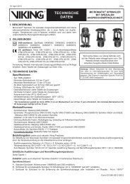
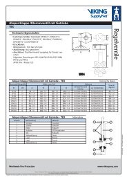
1. product description<br />
<strong>Viking</strong> Institutional Style Quick Response Standard Coverage/Extended Coverage<br />
Flush Pendent Sprinklers are small, flush, solder link and lever <strong>sprinkler</strong>s made with<br />
tamper-resistant construction. <strong>Viking</strong> <strong>institutional</strong> <strong>sprinkler</strong>s have been specifically<br />
designed for use with concealed piping in <strong>institutional</strong> mental health occupancies,<br />
correctional facilities, or anywhere a likelihood of tampering with fire <strong>sprinkler</strong>s by the<br />
occupants may exist.<br />
The <strong>institutional</strong> <strong>sprinkler</strong> assembly consists of the <strong>sprinkler</strong> body, lockring, and a 3-<br />
1/4” (82.6 mm) diameter thread-on escutcheon plate. The <strong>sprinkler</strong> and escutcheon<br />
plate have a polished chrome finish.<br />
Tests simulating conditions of misuse demonstrate the fusible element assembly<br />
consistently breaks away when connected to a 30 lb. (13.6 kg) weight dropped 6”<br />
(152 mm)†.<br />
† For a copy of the break-a-way test described, contact The <strong>Viking</strong> Corporation. The <strong>Viking</strong><br />
Corporation disclaims any responsibility for damages or injury (including death) caused by the operation or inoperation of <strong>sprinkler</strong>s arising out of<br />
the misuse of or tampering with <strong>Viking</strong> ® brand <strong>sprinkler</strong>s including, without limitation, any personal injury or death arising out of or caused by the<br />
manipulation of, dismantling of, or attempted use of the <strong>sprinkler</strong> or any component as an instrument unrelated to its intended use.<br />
2. listinGs and approvals<br />
culus listed: Category VNIV<br />
nYc approved: MEA 89-92-E, Volume 16<br />
cULus Listed as Quick Response Flush Pendent Sprinkler for standard areas of coverage in Light or Ordinary Hazard occupancies.<br />
Also cULus Listed for extended areas of coverage up to 16’ x 16’ (4.9 m x 4.9 m) in Light Hazard occupancies only. Refer to the<br />
Approval Chart on page 126c and Design Criteria on page 126d for cULus Listing requirements that must be followed.<br />
3. tecHnical data<br />
Specifications:<br />
Maximum Working Pressure: 175 psi (12 bar)<br />
Spring: U.S.A. Patent No. 4,570,720<br />
Thread size: 1/2” (15 mm) NPT<br />
Nominal K-Factor: 5.6 U.S. (80.6 metric*)<br />
*Metric K-factor measurement is shown in Bar. When pressure is measured in kPa, divide<br />
the metric K-factor shown by 10.0.<br />
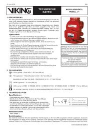
Overall Length: 2-9/32” (57.9 mm)<br />
Material standards:<br />
Sprinkler Body: Brass Casting UNS-C84400<br />
Body Cap: Stainless Steel UNS-S30400 or UNS-S30500<br />
Deflector: Copper UNS-C19500<br />
Deflector Pins: Stainless Steel UNS-S30300<br />
Button: UNS-C23000 H55-H80<br />
Compression Screw: Brass UNS-C36000<br />
Fusible Link Assembly: Beryllium Nickel and Eutectic Solder<br />
Fusible Link Levers: Stainless Steel UNS-S31600<br />
Lever Bar: Copper Alloy UNS-C72500<br />
Belleville Spring Sealing Assembly: Nickel Alloy, coated on both sides with Teflon Tape<br />
escutcheon Materials:<br />
Escutcheon Plate: Brass UNS-C26000<br />
Lockring: Stainless Steel UNS-S41000<br />
available Finishes and temperature ratings:<br />
Refer to Table 1<br />
viking technical data may be found on<br />
the viking corporation’s Web site at<br />
http://www.vikinggroupinc.com.<br />
Sprinkler 126a<br />
the Web site may include a more recent<br />
edition of this technical data page.<br />
Form No. F_100998 Revised page replaces page 126a-d dated December 20, 2002.<br />
(Reformatted, updated retaining flange dimensions.)
Sprinkler 126b<br />
tecHnical data<br />
December 1, 2006<br />
<strong>institutional</strong> <strong>quick</strong><br />
<strong>response</strong>/<strong>qrec</strong> <strong>FlusH</strong><br />
<strong>pendent</strong> <strong>sprinkler</strong><br />
vk410 (k5.6)<br />
the viking corporation, 210 n industrial park drive, Hastings Mi 49058<br />
telephone: 269-945-9501 technical services 877-384-5464 Fax: 269-945-4495 email: techsvcs@vikingcorp.com<br />
ordering instructions: (Also refer to the current <strong>Viking</strong> price list.)<br />
<strong>sprinkler</strong>: Base Part No. 10554<br />
Order Sprinkler VK410 by first adding the appropriate suffix for the <strong>sprinkler</strong> finish and then the appropriate suffix for the temperature<br />
rating to the <strong>sprinkler</strong> base part number.<br />
Finish Suffix: Polished Chrome = F<br />
Temperature Suffix (°F/°C): 165°/74° = C, 220°/104° = F<br />
For example, <strong>sprinkler</strong> VK410 with a 165 °F/74 °C temperature rating = Part No. 10554FC.<br />
Escutcheon Package Part No. 10627F (includes lockring and escutcheon plate).<br />
accessories: (Also refer to the “Sprinkler Accessories” section of the <strong>Viking</strong> data book.)<br />
<strong>sprinkler</strong> Wrenches*:<br />
A. Heavy Duty Part Number 08336W/B Available since 1983, or<br />
B. Light Duty Part Number 10366W/B** Available since 1998.<br />
*Requires a ½” ratchet (not available from <strong>Viking</strong>).<br />
**Ideal for <strong>sprinkler</strong> cabinets.<br />
<strong>institutional</strong> escutcheon installation Wrench: Part No. 10551W/B (available since 1999)<br />
spanner Wrench: Part No. 10729*** (for removal of <strong>institutional</strong> escutcheon plate), 2-1/2” C-C (available since 1999)<br />
***For removal of the Institutional Quick Response Flush Pendent Sprinklers, special tools are needed (not all the required tools are available from<br />
<strong>Viking</strong>). Refer to section 6. INSPECTIONS, TESTS, AND MAINTENANCE, paragraph D. on pages 126g-h.<br />
<strong>sprinkler</strong> cabinet:<br />
Six-head capacity: Part No. 01731A (available since 1971)<br />
retaining Flange assembly: Part No. 10599, includes: Retaining Flange Casting: AISI C1045 Low Carbon Steel (available<br />
since 1999)<br />
Thickness: 13/32” (10.3 mm)<br />
Outside Diameter: 2-3/4” (70 mm)<br />
Socket Set Screw††: Steel Alloy<br />
††Requires a 1/8” hex wrench for installation and removal (not available from <strong>Viking</strong>).<br />
4. installation<br />
(Refer to Figures 1-4.)<br />
WarninG: <strong>Viking</strong> <strong>sprinkler</strong>s are manufactured and tested to meet the rigid requirements of the approving agency. The <strong>sprinkler</strong>s<br />
are designed to be installed in accordance with recognized installation standards. Deviation from the standards or any alteration<br />
to the <strong>sprinkler</strong> after it leaves the factory including, but not limited to: painting, plating, coating, or modification, may render the<br />
<strong>sprinkler</strong> inoperative and will automatically nullify the approval and any guarantee made by The <strong>Viking</strong> Corporation. Flush <strong>sprinkler</strong>s<br />
are decorative <strong>sprinkler</strong>s and may be considered special purpose. As such, some Authorities may limit the use depending on the<br />
occupancy classification. Refer to the Authority Having Jurisdiction prior to installation.<br />
<strong>sprinkler</strong> temperature classification<br />
<strong>sprinkler</strong> Finish: Polished Chrome<br />
taBle 1: availaBle <strong>sprinkler</strong> teMperature ratinGs and FinisHes<br />
<strong>sprinkler</strong> nominal<br />
temperature rating 1<br />
Maximum ambient<br />
ceiling temperature 2<br />
Ordinary 165 °F (74 °C) 100 °F (38 °C)<br />
Intermediate 220 °F (104 °C) 150 °F (65 °C)<br />
1 The <strong>sprinkler</strong> temperature rating is stamped on the <strong>sprinkler</strong>.<br />
Footnotes<br />
2 Based on NFPA-13. Other limits may apply, depending on fire loading, <strong>sprinkler</strong> location, and other requirements of the Authority Having<br />
Jurisdiction. Refer to specific installation standards.
December 1, 2006<br />
tecHnical data<br />
<strong>institutional</strong> <strong>quick</strong><br />
<strong>response</strong>/<strong>qrec</strong> <strong>FlusH</strong><br />
<strong>pendent</strong> <strong>sprinkler</strong><br />
vk410 (k5.6)<br />
the viking corporation, 210 n industrial park drive, Hastings Mi 49058<br />
telephone: 269-945-9501 technical services 877-384-5464 Fax: 269-945-4495 email: techsvcs@vikingcorp.com<br />
<strong>sprinkler</strong> Base<br />
part number 1<br />
approval chart<br />
<strong>institutional</strong> style <strong>quick</strong> <strong>response</strong> Flush <strong>pendent</strong> <strong>sprinkler</strong> sin vk410<br />
Maximum 175 psi (12 bar) WWp<br />
npt thread size nominal k-Factor overall length<br />
inches mm u.s. metric 2 inches mm<br />
listings and approvals 3<br />
(refer also to design criteria on page 126d.)<br />
10554 1/2 15 5.6 80.6 2-9/32 57.9 culus 4 FM nYc 6 vds lpcB<br />
standard coverage applications - For light and ordinary Hazard occupancies A1 -- B1 -- -- -- --<br />
extended coverage applications - For light Hazard occupancies only<br />
Maximum area of coverage: 16’ x 16’ (4.9 m x 4.9 m)<br />
Minimum Water supply requirements: 26 gpm @ 21.6 psi (98.4 L/min @ 1.49 bar)<br />
approved temperature ratings<br />
A - 165 °F (74 °C) and 220 °F (104 °C)<br />
B - 165 °F (74 °C)<br />
Footnotes<br />
culus 5 FM nYc vds lpcB<br />
A1 -- -- -- -- -- --<br />
approved Finish<br />
1 - Polished Chrome<br />
1 Part number shown is the base part number. For complete part number, refer to current <strong>Viking</strong> price list schedule.<br />
2 Metric K-factor measurement shown is when pressure is measured in Bar. When pressure is measured in kPa, divide the metric K-factor shown<br />
by 10.0.<br />
3 This chart shows the listings and approvals available at the time of printing. Other approvals may be in process. Check with the manufacturer<br />
for any additional approvals.<br />
4 Listed by Underwriter’s Laboratories for use in the U.S. and Canada as a Quick Response Flush Pendent Sprinkler for standard areas of<br />
coverage.<br />
5 Listed by Underwriter’s Laboratories for use in the U.S. and Canada as a Quick Response Extended Coverage Flush Pendent Sprinkler<br />
for Light Hazard occupancies only.<br />
6 Accepted for use, City of New York Department of Buildings, MEA Number 89-92-E, Vol. 16.<br />
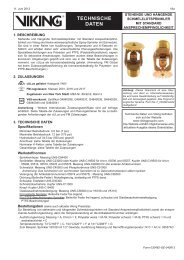
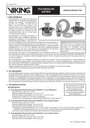
Figure 1: <strong>sprinkler</strong> Body, lockring, and escutcheon plate<br />
Figure 2: retaining Flange<br />
Sprinker 126c
Sprinkler 126d<br />
tecHnical data<br />
December 1, 2006<br />
<strong>institutional</strong> <strong>quick</strong><br />
<strong>response</strong>/<strong>qrec</strong> <strong>FlusH</strong><br />
<strong>pendent</strong> <strong>sprinkler</strong><br />
vk410 (k5.6)<br />
the viking corporation, 210 n industrial park drive, Hastings Mi 49058<br />
telephone: 269-945-9501 technical services 877-384-5464 Fax: 269-945-4495 email: techsvcs@vikingcorp.com<br />
culus listing requirements for standard coverage applications:<br />
desiGn criteria<br />
(Also refer to the Approval Chart on page 126c)<br />
Sprinkler VK410 is cULus Listed as a Quick Response Flush Pendent Sprinkler for standard areas of coverage as indicated in the Approval Chart for<br />
installation in accordance with the latest edition of NFPA 13.<br />
•<br />
•<br />
•<br />
•<br />
•<br />
•<br />
•<br />
Designed for use in Light and Ordinary Hazard occupancies.<br />
The <strong>sprinkler</strong> must be installed in the <strong>pendent</strong> position in fixed fire protection systems (wet, dry, deluge, or preaction systems).<br />
Protection areas and maximum spacing shall be in accordance with the tables provided in NFPA 13.<br />
Minimum spacing allowed is 6 ft. (1.8 m) unless baffles are installed in accordance with NFPA 13.<br />
Minimum distance from walls is 4 in. (102 mm).<br />
Maximum distance from walls shall be no more than one-half of the allowable distance between <strong>sprinkler</strong>s. The distance shall be measured<br />
perpendicular to the wall.<br />
The <strong>sprinkler</strong> installation and obstruction rules contained in NFPA 13 for standard coverage spray <strong>pendent</strong> <strong>sprinkler</strong>s must be followed.<br />
culus listing requirements for extended coverage applications:<br />
Sprinkler VK410 is cULus Listed as a Quick Response Extended Coverage Flush Pendent Sprinkler as indicated in the Approval Chart for installation<br />
in accordance with the latest edition of NFPA 13 for extended coverage <strong>pendent</strong> spray <strong>sprinkler</strong>s.<br />
•<br />
•<br />
•<br />
•<br />
•<br />
Designed for use in Light Hazard occupancies only.<br />
The <strong>sprinkler</strong> must be installed in the <strong>pendent</strong> position in fixed fire protection systems (wet, dry, deluge, or preaction systems).<br />
Minimum distance from walls is 4 in. (102 mm).<br />
Maximum distance from walls shall be no more than one-half of the allowable distance between <strong>sprinkler</strong>s. The distance shall be measured<br />
perpendicular to the wall.<br />
The <strong>sprinkler</strong> installation and obstruction rules contained in NFPA 13 for extended coverage <strong>pendent</strong> spray <strong>sprinkler</strong>s must be followed.<br />
iMportant: always refer to Bulletin Form no. F_091699 - care and Handling of <strong>sprinkler</strong>s. also refer to page<br />
qr1-2 or ec1-2 for general care, installation, and maintenance information. viking <strong>sprinkler</strong>s are to be installed<br />
in accordance with the latest edition of viking technical data, the appropriate standards of nFpa, FM Global,<br />
lpcB, apsad, vds or other similar organizations, and also with the provisions of governmental codes, ordinances,<br />
and standards, whenever applicable.<br />
A. Sprinklers must be handled with care. They must be stored in a cool, dry place in their original shipping container. Never install<br />
<strong>sprinkler</strong>s that have been dropped, damaged in any way, or exposed to temperatures in excess of maximum ambient temperature<br />
allowed. Such <strong>sprinkler</strong>s should be destroyed immediately.<br />
B. <strong>Viking</strong> Institutional Quick Response Flush Pendent Sprinklers are not intended for use in corrosive environments. Use only<br />
<strong>sprinkler</strong>s listed for corrosive environments when subject to corrosive atmospheres.<br />
C. Use care when locating <strong>sprinkler</strong>s near fixtures that can generate heat. Do not install <strong>sprinkler</strong>s where they will be exposed to<br />
temperatures that exceed the maximum recommended ambient temperature for the temperature rating used.<br />
D. Adequate heat must be provided when the Institutional Quick Response Flush Pendent Sprinkler is installed on wet-pipe systems.<br />
E. The <strong>sprinkler</strong>s must be installed after the piping is in place to prevent mechanical damage. Before installing, be sure to have the<br />
appropriate <strong>sprinkler</strong> model and style, with the correct orifice size, temperature rating, and <strong>response</strong> characteristics. Install the<br />
<strong>sprinkler</strong>s according to the following sequence:<br />
1. Install all piping and cut the <strong>sprinkler</strong> drop nipple so that the ½” (15 mm) NPT outlet of the reducing coupling is at the desired<br />
elevation and centered in a 2-1/4” (57.2 mm) diameter opening in the ceiling (due to lockring). Note: If the retaining flange<br />
assembly is to be used, slide the flange over the <strong>sprinkler</strong> drop nipple prior to threading the nipple into the branch line tee<br />
as shown in Figure 4-A.<br />
2. The internal diameter of the special Flush/Concealed Sprinkler Wrench is designed for use with the <strong>sprinkler</strong> contained in the<br />
protective plastic shell. With the <strong>sprinkler</strong> in the shell, apply a small amount of pipe-joint compound or tape to the external<br />
threads of the <strong>sprinkler</strong> only, taking care not to allow a build-up of compound in the <strong>sprinkler</strong> inlet.
December 1, 2006<br />
tecHnical data<br />
Sprinkler 126e<br />
<strong>institutional</strong> <strong>quick</strong><br />
<strong>response</strong>/<strong>qrec</strong> <strong>FlusH</strong><br />
<strong>pendent</strong> <strong>sprinkler</strong><br />
vk410 (k5.6)<br />
the viking corporation, 210 n industrial park drive, Hastings Mi 49058<br />
telephone: 269-945-9501 technical services 877-384-5464 Fax: 269-945-4495 email: techsvcs@vikingcorp.com<br />
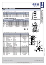
Figure 3: <strong>sprinkler</strong> dimensions and installation adjustment<br />
3. Refer to Figure 4-B and use only Sprinkler Wrench 08336W/B or 10366W/B, which is designed for installing <strong>Viking</strong> Institutional<br />
Quick Response Flush Pendent Sprinklers. With the <strong>sprinkler</strong> in the plastic protective shell, place the unit into the wrench.<br />
DO NOT use the fusible link to start or thread the <strong>sprinkler</strong> into a fitting. Turn the unit clockwise to thread the <strong>sprinkler</strong> into<br />
the coupling, taking care not to over-tighten or damage the <strong>sprinkler</strong> operating parts.<br />
F. After installation, the entire system must be tested in accordance with recognized installation standards. The test is applied after<br />
<strong>sprinkler</strong> installation to ensure that no damage has occurred to the <strong>sprinkler</strong> during shipping and installation, and to make sure<br />
the unit has been properly tightened. If a thread leak occurs, normally the unit must be removed, new pipe-joint compound or<br />
tape applied, and then reinstalled. This is due to the fact that when the joint seal leaks, the sealing compound or tape is washed<br />
out of the joint.<br />
G. After testing, repairing all leaks, and installing and painting the ceiling, remove the plastic protective shell from the <strong>sprinkler</strong>.<br />
installation tip: Do NOT install the lockring onto the <strong>sprinkler</strong> until after the <strong>sprinkler</strong> nipple has been cut back to ensure the <strong>sprinkler</strong><br />
is at the desired elevation in relation to the face of the ceiling. The lockring will prove difficult to remove from the <strong>sprinkler</strong> once it has<br />
been installed above the plane of the ceiling. Check final installation by temporarily installing the escutcheon plate onto the <strong>sprinkler</strong><br />
without the lockring, using Institutional Escutcheon Installation Wrench 10551W/B. If necessary, re-cut the <strong>sprinkler</strong> nipple as required.<br />
Once satisfied with <strong>sprinkler</strong> level compared to the surface of the ceiling, install lockring and escutcheon plate following the steps<br />
below. The escutcheon plate cannot be removed after it has been installed with the lockring, so do not install the escutcheon<br />
plate with the lockring until after the system has been tested.<br />
H. As shown in Figure 4-C and D, fit the lockring over the open end of the protective <strong>sprinkler</strong> shell and use the shell to gently press<br />
the lockring over the threads of the <strong>sprinkler</strong>. The ring must rest against the two wrench ears of the <strong>sprinkler</strong> body with the four<br />
arms of the lockring pointing outward.<br />
I. REMOVE THE PLASTIC PROTECTIVE SHELL from the <strong>sprinkler</strong>. (Recommendation: retain a protective shell in the spare<br />
<strong>sprinkler</strong> cabinet.)
Sprinkler 126f<br />
tecHnical data<br />
December 1, 2006<br />
<strong>institutional</strong> <strong>quick</strong><br />
<strong>response</strong>/<strong>qrec</strong> <strong>FlusH</strong><br />
<strong>pendent</strong> <strong>sprinkler</strong><br />
vk410 (k5.6)<br />
the viking corporation, 210 n industrial park drive, Hastings Mi 49058<br />
telephone: 269-945-9501 technical services 877-384-5464 Fax: 269-945-4495 email: techsvcs@vikingcorp.com<br />
installation tip:<br />
do not install the lockring onto the <strong>sprinkler</strong> until after the <strong>sprinkler</strong> nipple has been cut back to ensure the <strong>sprinkler</strong> is at the desired<br />
elevation in relation to the face of the ceiling. the lockring will prove difficult to remove from the <strong>sprinkler</strong> once it has been installed<br />
above the plane of the ceiling. check final installation by temporarily installing the escutcheon plate onto the <strong>sprinkler</strong> without the<br />
lockring, using the <strong>institutional</strong> escutcheon installation Wrench. if necessary, re-cut the <strong>sprinkler</strong> drop nipple as required.<br />
once satisfied with <strong>sprinkler</strong> level compared to the surface of the ceiling, install lockring and escutcheon plate following<br />
steps H through J below. the escutcheon plate cannot be removed after it has been installed with the lockring,<br />
so do not install the escutcheon plate with the lockring until after the system has been tested.<br />
Figure 4: sequence of installation<br />
J. As depicted in Figure 4-E, use the Institutional Escutcheon Installation Wrench to screw on the escutcheon plate clockwise.<br />
The face of the escutcheon plate is equipped with four indentations to complement the design of the Institutional Escutcheon<br />
Installation Wrench 10551W/B and facilitate installation of the escutcheon plate. As the escutcheon plate is threaded onto<br />
the <strong>sprinkler</strong> body, the four arms of the lockring must fully engage with the radial grooves on the inside of the escutcheon<br />
plate. Continue to thread the escutcheon plate onto the <strong>sprinkler</strong> body until the plate’s flange fits tightly against the surface<br />
of the ceiling. Then, proceed to turn the escutcheon plate another ½ turn clockwise to ensure that it is secured to the ceiling.<br />
The arms of the lockring are angled and designed to wedge into the coined radial grooves on the inside face of the escutcheon<br />
plate to keep the escutcheon plate from being unscrewed. Thus, an attempt to remove the escutcheon plate after installation is<br />
prevented. DO NOT MODIFY THE UNIT.<br />
K. The retaining flange, located behind the finished ceiling, must fit snug against the inner surface of the ceiling to prevent vertical<br />
movement of the assembly. Use a 1/8” hex wrench to tighten the retaining flange screw and secure the assembly into place to<br />
prevent it from being pulled through the ceiling.<br />
L. DISASSEMBLY: Refer to section 6. INSPECTIONS, TESTS AND MAINTENANCE, paragraph D. and follow all warnings and<br />
instructions.<br />
5. operation<br />
The <strong>sprinkler</strong> is recessed into the mounting surface, flush to the ceiling, with only a portion of the fusible link assembly exposed<br />
beneath the ceiling. The concealed deflector is held inside the <strong>sprinkler</strong> body until the eutectic metal solder link is fused. When the<br />
<strong>sprinkler</strong> fuses, the deflector extends to discharge and distribute water. The multi-piece design allows the installation and testing of<br />
the <strong>institutional</strong> <strong>sprinkler</strong>s prior to installation of the ceiling.<br />
The special escutcheon plate on the Institutional Quick Response Flush Pendent Sprinkler assembly is the only ceiling ring that<br />
may be used with these <strong>institutional</strong> <strong>sprinkler</strong>s, and all of these <strong>sprinkler</strong>s must be installed with this escutcheon plate. Removal of<br />
the thread-on escutcheon plate is prevented by the lockring.
December 1, 2006<br />
tecHnical data<br />
<strong>institutional</strong> <strong>quick</strong><br />
<strong>response</strong>/<strong>qrec</strong> <strong>FlusH</strong><br />
<strong>pendent</strong> <strong>sprinkler</strong><br />
vk410 (k5.6)<br />
the viking corporation, 210 n industrial park drive, Hastings Mi 49058<br />
telephone: 269-945-9501 technical services 877-384-5464 Fax: 269-945-4495 email: techsvcs@vikingcorp.com<br />
The <strong>sprinkler</strong> pipe above the ceiling leading to the <strong>sprinkler</strong> must be secured to prevent any movement of the <strong>sprinkler</strong>. One method<br />
of anchoring the pipe above the ceiling is to use the retaining flange and screw assembly that are available from <strong>Viking</strong>. The flange<br />
slides over the <strong>sprinkler</strong> drop nipple prior to threading the nipple into the branch line tee (see Figure 4-A).<br />
6. inspections, tests and Maintenance<br />
(Refer to Figures 1-4.)<br />
notice: The owner is responsible for maintaining the fire protection system and devices in proper operating condition. For minimum<br />
maintenance and inspection requirements, refer to NFPA 25 for Inspection, Testing and Maintenance requirements. In addition,<br />
the Authority Having Jurisdiction may have additional maintenance requirements that must be followed.<br />
A. The <strong>sprinkler</strong>s must be inspected on a regular basis for corrosion, mechanical damage, obstructions, paint, etc. The frequency<br />
of inspections may vary due to corrosive atmospheres, water supplies, and activity around the device.<br />
B. Sprinklers that have been painted or mechanically damaged must be replaced immediately. Sprinklers showing signs of corrosion<br />
shall be tested and/or replaced immediately as required. Installation standards require <strong>sprinkler</strong>s to be tested and, if necessary,<br />
replaced after a specified term of service. Refer to the installation standards and the Authority Having Jurisdiction for the<br />
specified period of time after which testing and/or replacement is required. Sprinklers that have operated cannot be reassembled<br />
or reused, but must be replaced. When replacing <strong>sprinkler</strong>s, use only new <strong>sprinkler</strong>s.<br />
C. The <strong>sprinkler</strong> discharge pattern is critical for proper fire protection. Nothing should be hung from the <strong>sprinkler</strong>, attached to it, or<br />
otherwise obstruct the discharge pattern. All obstructions must be immediately removed or, if necessary, additional <strong>sprinkler</strong>s<br />
installed.<br />
D. When replacing existing <strong>sprinkler</strong>s, the system must be removed from service. Refer to the appropriate system description and/<br />
or valve instructions. Prior to removing the system from service, notify all Authorities Having Jurisdiction. Consideration should<br />
be given to employment of a fire patrol in the affected area.<br />
disasseMBlY: There are two methods of <strong>sprinkler</strong> disassembly. In Method 1, the escutcheon plate and lockring are removed<br />
first, and then the remaining <strong>sprinkler</strong> components can be removed without being destroyed. The second method of disassembly<br />
results in complete destruction of the unit.<br />
disassembly Method 1:<br />
1. Remove the system from service, drain all water, and relieve<br />
all pressure on the piping.<br />
2. Use a drill (not available from <strong>Viking</strong>) sized appropriately for<br />
use with a spanner wrench (see step 3) to make two holes<br />
through two opposite indentations on the face of the escutcheon<br />
plate.<br />
3. Use a 2-1/2” C-C spanner wrench (<strong>Viking</strong> Part No. 10729) to unthread the escutcheon plate by turning it counterclockwise.<br />
Make sure that the <strong>sprinkler</strong> body does not turn or loosen.<br />
4. Remove the lockring from the <strong>sprinkler</strong> body.<br />
5. Place a protective <strong>sprinkler</strong> shell (from the spare <strong>sprinkler</strong> cabinet) over the <strong>sprinkler</strong> to be removed.<br />
6. With the protective shell over the <strong>sprinkler</strong>, place Sprinkler Wrench 08336W/B or 10366W/B over the unit and turn it counterclockwise<br />
to carefully unthread the <strong>sprinkler</strong> body from the reducing coupling.<br />
7. Install the new unit using the <strong>sprinkler</strong> wrench. Care must be taken to ensure that the replacement <strong>sprinkler</strong> is the proper<br />
model and style, with the appropriate orifice size, temperature rating, and <strong>response</strong> characteristics. A fully stocked spare<br />
<strong>sprinkler</strong> cabinet should be provided for this purpose. (Stock of spare lockrings and escutcheon plates should be available<br />
in the spare <strong>sprinkler</strong> cabinet in addition to the spare <strong>sprinkler</strong> heads.)<br />
8. Place the system back in service and secure all valves. Check for and repair all leaks.<br />
disassembly Method 2:<br />
1. Remove the system from service, drain all water, and<br />
relieve all pressure on the piping.<br />
2. Disassemble and remove the fusible element, and bend<br />
the deflector and sealing assembly to expose the waterway<br />
of the <strong>sprinkler</strong>.<br />
Sprinkler 126g<br />
note: disassembly Method 1 results in damage to the<br />
escutcheon plate and lockring, and they cannot be reused.<br />
note: disassembly Method 2 results in complete destruction of<br />
the unit. none of the <strong>sprinkler</strong> components may be reused.<br />
3. Insert an easy-out screw extractor (Trade No. 6) into the waterway. Turn the easy-out counterclockwise with a wrench to<br />
remove the <strong>sprinkler</strong> assembly from the reducing coupling.
Sprinkler 126h<br />
tecHnical data<br />
December 1, 2006<br />
<strong>institutional</strong> <strong>quick</strong><br />
<strong>response</strong>/<strong>qrec</strong> <strong>FlusH</strong><br />
<strong>pendent</strong> <strong>sprinkler</strong><br />
vk410 (k5.6)<br />
the viking corporation, 210 n industrial park drive, Hastings Mi 49058<br />
telephone: 269-945-9501 technical services 877-384-5464 Fax: 269-945-4495 email: techsvcs@vikingcorp.com<br />
4. Install the new unit using Sprinkler Wrench 08336W/B or 10366W/B. Care must be taken to ensure that the replacement<br />
<strong>sprinkler</strong> is the proper model and style, with the appropriate orifice size, temperature rating, and <strong>response</strong> characteristics. A<br />
fully stocked spare <strong>sprinkler</strong> cabinet should be provided for this purpose. (Stock of spare lockrings and escutcheon plates<br />
should be available in the spare <strong>sprinkler</strong> cabinet in addition to the spare <strong>sprinkler</strong> heads.)<br />
5. Place the system back in service and secure all valves. Check for and repair all leaks.<br />
E. Sprinkler systems that have been subject to a fire must be returned to service as soon as possible. The entire system must<br />
be inspected for damage and repaired or replaced as necessary. Sprinklers that have been exposed to corrosive products of<br />
combustion or high ambient temperatures, but have not operated, should be replaced. Refer to the Authority Having Jurisdiction<br />
for minimum replacement requirements.<br />
7. availaBilitY<br />
<strong>Viking</strong> Sprinkler VK410 is available through a network of domestic and international distributors. See The <strong>Viking</strong> Corporation web<br />
site for the closest distributor or contact The <strong>Viking</strong> Corporation.<br />
8. Guarantee<br />
For details of warranty, refer to <strong>Viking</strong>’s current list price schedule or contact <strong>Viking</strong> directly.<br />
9. disclaiMer<br />
THE VIKING CORPORATION DISCLAIMS ANY RESPONSIBILITY FOR DAMAGES OR INJURY (INCLUDING DEATH) CAUSED<br />
BY THE OPERATION OR INOPERATION OF SPRINKLERS ARISING OUT OF THE MISUSE OF OR TAMPERING WITH VIKING ®<br />
BRAND SPRINKLERS INCLUDING, WITHOUT LIMITATION, ANY PERSONAL INJURY OR DEATH ARISING OUT OF OR<br />
CAUSED BY THE MANIPULATION OF, DISMANTLING OF, OR ATTEMPTED USE OF THE SPRINKLER OR ANY COMPONENT<br />
AS AN INSTRUMENT UNRELATED TO ITS INTENDED USE.<br />
Form No. F_100998 Revised page replaces page 126a-d dated December 20, 2002.<br />
(Reformatted, updated retaining flange dimensions.)