Electro-Spark Coating with Special Materials - nonconventional ...
Electro-Spark Coating with Special Materials - nonconventional ...
Electro-Spark Coating with Special Materials - nonconventional ...

You also want an ePaper? Increase the reach of your titles
YUMPU automatically turns print PDFs into web optimized ePapers that Google loves.
ELECTRO-SPARK COATING WITH SPECIAL MATERIALS<br />
Victor VERBITCHI*; Cristian CIUCA*; Radu COJOCARU*<br />
* National Research and Development Institute for Welding and Material Testing - ISIM Timisoara,<br />
Bd. Mihai Viteazul, Nr.30, Postal code 300222, Timisoara, Romania;<br />
e-mail: vverbitchi@isim.ro; cciuca@isim.ro; rcojocaru@isim.ro<br />
ABSTRACT: The electro-spark coating is a deposition process. Consumable electrodes are used, made of<br />
stainless steel, nickel, other metals, sintered tungsten carbide, metal-ceramics or ceramics. Specific<br />
characteristics and applications possibilities are presented, such as small area reclaiming of tools, dies and<br />
valves. An experimental model made by ISIM of Timisoara is described. It generates electric sparks between<br />
a rotating electrode and a base metal. Some experiments and results are also presented and discussed. The<br />
thickness of the coating is 0.01…0.5 mm. There is no distortion of the base metal. The operator has full<br />
control on the process. The deposition rate depends on the power of the device (0.160...1.6 kVA).<br />
Keywords: electro-spark coating, deposition, electrodes, special materials, spark generating,<br />
material transfer, small reclaiming, reduced distortion.<br />
1. INTRODUCTION<br />
In the most cases, in the manufacturing<br />
process of the moulds and dies, the final<br />
operation consists in applying some thermal<br />
treatments, as quenching, annealing, etc. But<br />
the industrial practise has demonstrated the<br />
increasing need for harder and more ductile<br />
materials, that have a higher resistance in<br />
time and are easier for processing [1-4].<br />
There are several thermal-chemical<br />
treatments widely used, as nitriding, physical<br />
vapor deposition (PVD), chemical vapor<br />
deposition (CVD), electroplating, thermal<br />
diffusion (TD), etc., that improve the wear or<br />
corrosoin resistance. The equipment cost,<br />
process duration and pollution of the<br />
environment are only a few of the<br />
disadvantages of these methods. Instead, the<br />
electro-spark coating and deposition<br />
processes can eliminate these difficulties.<br />
2. ELECTRO-SPARK DEPOSITION<br />
As the instantaneous temperature of the<br />
spark is about 25,000 ˚C, fusion of some fine<br />
drops of the electrode material takes place,<br />
that are ejected upon the base metal and<br />
form a compact deposition, only <strong>with</strong> local<br />
heating, so that no transformations and<br />
distortions of the base metal occur. This<br />
technological process was contrived to<br />
perform electro-spark coating, having the<br />
thickness 0.01 ... 0.5 mm [1,3], respectively<br />
electrospark depositions, <strong>with</strong> the thickness<br />
Nonconventional Technologies Review – no. 1/2011<br />
57<br />
0.5 ... 3.0 mm [2,4], for improving the some<br />
functional proprieties or repairing some parts.<br />
These represent functional variants, <strong>with</strong><br />
applicative character of a non-conventional<br />
technology [1-5].<br />
The consumable electrode is in a relative<br />
movement against the base metal, by rotation<br />
or vibration. The electric sparks are produced<br />
by an electric circuit, that consists generally<br />
of a spark generator and a capacitor, that<br />
charges from the generator and discharges<br />
periodically in a secondary circuit, as it closes<br />
by means of the contact between the<br />
electrode and the workpiece.<br />
This process replaced the detonation-gun<br />
or HVOF processes and provided orders of<br />
magnitude increase in wear and damage<br />
resistance, a five-fold improvement in<br />
corrosion performance, lower friction, and<br />
more than a 50% saving in cost, <strong>with</strong> the<br />
same material. The process was in<br />
production of nuclear components for 10<br />
years, <strong>with</strong> no failure or reject [3].<br />
<strong>Electro</strong>-spark Deposition (ESD) is a microwelding<br />
process, which uses electrical pulses<br />
frequencies in the 0.1... 2 kHz range and thus<br />
allow substrate heat dissipation over ~99% of<br />
the duty cycle, while heating only ~1%. The<br />
result is cooling rates of 10 5 to 10 6 ○ C/sec,<br />
and generation of nano-structures,<br />
amorphous for some alloys, <strong>with</strong> corrosion<br />
and tribological benefits. This also eliminates<br />
thermal distortions.<br />
The ESD are among the most damageresistant<br />
coatings, suitable for high stresses,
high temperatures, thermal cycling,<br />
irradiation, wear, corrosion, and erosion. An<br />
applications is the three-times increase in life<br />
of high-speed steel milling cutters after ESD<br />
<strong>with</strong> tungsten carbide. Other application are:<br />
ship propeller components, casting moulds,<br />
fuel supply system parts, exhaust system<br />
components, implants or cutting tools [3].<br />
The ESD coating is realized in an<br />
environment of local high temperature and<br />
pressure [3]: shock wave pressure from the<br />
electric spark (2...7)•10 3 GPa; temperature<br />
(5...40)•10 3 °Celsius. Deposition times are<br />
several minutes per cm 2 .<br />
A generator for the electro-spark coating<br />
and depositing is presented in fig.1.<br />
Fig. 1. Generator for the electro-spark<br />
coating and deposition [1]<br />
The deposits are realized <strong>with</strong> various filler<br />
materials, depending on the characteristics<br />
intended to be obtained: high hardness, good<br />
wear resistance, anti-corrosive proprieties,<br />
decorative objects, thermal barriers, etc.<br />
Table 1. <strong>Electro</strong>des of special materials<br />
for electro-spark coating/depositing [1-3]<br />
<strong>Electro</strong>de<br />
type<br />
LT-01<br />
LT-02<br />
LT-03<br />
LT-04<br />
LT-05<br />
LT-06<br />
Sizes<br />
Φ x L<br />
[mm]<br />
2,4 x<br />
100<br />
3,3 x<br />
100<br />
3,3 x<br />
100<br />
2,4 x<br />
100<br />
2,2 x<br />
100<br />
2,2 x<br />
100<br />
Material<br />
Ni alloy<br />
Cr-Co<br />
alloy,<br />
stellite<br />
Cr-Co<br />
alloy,<br />
stellite<br />
alloy<br />
steel<br />
alloy<br />
steel<br />
alloy<br />
steel<br />
Nonconventional Technologies Review – no. 1/2011<br />
Hardness<br />
[HRC]<br />
40<br />
62<br />
55-58<br />
45-50<br />
35<br />
34<br />
Frequen<br />
cy<br />
[Hz]<br />
C / D<br />
50-60<br />
90-110<br />
50-60<br />
90-110<br />
50-60<br />
90-110<br />
50-60<br />
90-100<br />
50-60<br />
90-100<br />
50-60<br />
80-90<br />
Thickness<br />
max.<br />
[mm]<br />
3<br />
1<br />
1<br />
3<br />
3<br />
3<br />
58<br />
<strong>Electro</strong>de<br />
type<br />
LT-07<br />
LT-08<br />
A1-01<br />
TC=01<br />
TC-02<br />
Sizes<br />
Φ x L<br />
[mm]<br />
2,2 x<br />
100<br />
2,2 x<br />
100<br />
2,0 x<br />
100<br />
3,3 x<br />
100<br />
2,2 x<br />
100<br />
Material <br />
Hardness<br />
[HRC]<br />
inco- nel 29<br />
stain<br />
less<br />
steel<br />
alumi<br />
nium<br />
tungsten<br />
car-bide<br />
tungsten<br />
car-bide<br />
21<br />
-<br />
Frequen<br />
cy<br />
[Hz]<br />
C / D<br />
50-60<br />
90-110<br />
50-60<br />
90-110<br />
50-60<br />
130-150<br />
Thickness<br />
max.<br />
[mm]<br />
3<br />
3<br />
3<br />
on cast<br />
Al<br />
90-95 40-100 0.05<br />
90-65<br />
40-80<br />
0.05<br />
Note. C is electro-spark coating. D is electrospark<br />
depositing.<br />
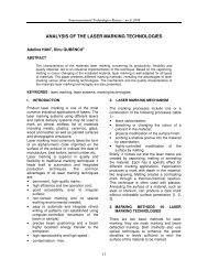
3. EXPERIMENTAL MODEL<br />
ISIM of Timisoara has contrived and realized<br />
an experimental model device for electrospark<br />
coating, shown in fig. 2 [6].<br />
Fig. 2. Device for electro-spark coating [6]<br />
The device has the following functions,<br />
that asure the specific technology<br />
requirements of the process [6]:<br />
a. Generating electric discharges, as sparks,<br />
over a gap (approximately 0.1...0.5 mm)<br />
between the electrode of the device and the<br />
base metal workpiece, as well as the transfer<br />
of the filler material of the electrode, as small<br />
drops, unto the base metal. The spark-based<br />
material transfer is the key of the process.<br />
b. Rotating movement of the electrode,<br />
necessary for avoiding the accidental<br />
welding of the consumable electrode on the<br />
workpiece, on which the coating or the<br />
depositing is made. The rotating motion is
performed by a servomotor, by means of a<br />
flexible, torsion-resistant cable, about<br />
1.0...1.15 m long; the cable rotates in a<br />
flexible guiding tube; by this cable the electric<br />
connection is also made for the depositing<br />
current of 2...3 A; the inlet connection of the<br />
power current is realized by means of two<br />
graphite contact brushes, having a section of<br />
9mm x 20mm, placed on both sides of the<br />
electrode rotating axle.<br />
3.1. Generator for electro-spark<br />
coating<br />
A reduced-power spark generator was<br />
realized, having the following characteristics:<br />
installed power S= 160 VA; open-circuit<br />
voltage U0 = 55 V; frequency f= 50 Hz; shortcircuit<br />
current Isc= 4 A; duty factor DA 10%.<br />
3.2. Servomotor drive block<br />
This block has the following components:<br />
- rotational speed regulator;<br />
- servomotor (24 VDC; 120 W; 5000 rot/min);<br />
- worm reducer (i= 1/40);<br />
- mechanical drive unit.<br />
The rotational speed of the electrode can<br />
be set in the continuous range n= 0... 60<br />
rot/min. The pre-set speed is realized by a<br />
speed regulator. This is a pulse width<br />
modulation (PWM) electronic-set, <strong>with</strong><br />
thyristors, operating at the mains frequency.<br />
It keeps the pre-set speed by compensating<br />
the voltage drop over the rotor coils, during<br />
the load operation, for any extent of the<br />
torque, respectively of the load current, in the<br />
operation range. In a certain connection, this<br />
regulator can utilize the electro-motive force<br />
of the rotor armature for stabilizing the speed.<br />
The regulator can also operate at higher<br />
frequencies, if necessary.<br />
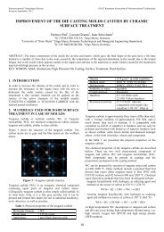
Fig. 3. <strong>Spark</strong>s aplicator (device tool) [6]<br />
In fig.3 the sparks aplicator (tool of the<br />
electro-sparks device) is presented.<br />
Nonconventional Technologies Review – no. 1/2011<br />
59<br />
4. EXPERIMENTS<br />
A. <strong>Electro</strong>-spark coating <strong>with</strong> a<br />
stainless steel electrode<br />
On the experimental model, some<br />
experiments have been done, <strong>with</strong> the<br />
purposes of verifying the model and the<br />
possibilities of the process, concerning the<br />
main characteristics of the coating [6].<br />
A sample of steel S235JR, according to<br />
EN10027, was prepared, <strong>with</strong> the sizes<br />
60mm x 50mm x 25 mm, on which local<br />
coatings were made.<br />
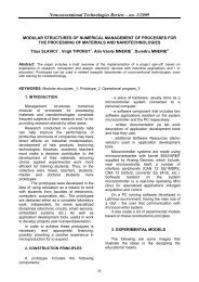
In fig. 4 an image of the electro-spark coating<br />
process , <strong>with</strong> stainless steel on steel<br />
S235JR is presented.<br />
Fig. 4. Experiments <strong>with</strong> the electro-spark<br />
coating process [6]<br />
<strong>Electro</strong>-spark coatings were performed<br />
using a stainless steel electrode Φ2,5mm.<br />
The parameters of the process were:<br />
- <strong>Electro</strong>de tilt angle, related to horizontal: 20º<br />
- <strong>Electro</strong>de rotative-speed 40-50 rev/min,<br />
- Open-circuit voltage 55 V,<br />
- Load voltage 25...45 V,<br />
- Average current 2.0...3.5 A,<br />
- Travel speed 2...4 mm / min,<br />
- Cross oscillation amplitude 10...12mm ,<br />
- Cross oscillation frequency 0.2...1.0 Hz.<br />
In 10 min, a coating of 10mm x 12mm and<br />
0.05...0.10 mm thick can be made.<br />
In order to obtain uniform coatings,<br />
referring to thickness and aspect, constant<br />
speed of the electrode travel and oscillating<br />
movements during the process are<br />
necessary. These requirements depend on<br />
the professional skills and physical status of<br />
the welding operator, that are not stable. This<br />
inconvenient can be taken away by<br />
implementing a mechanized, automated or<br />
robot process, <strong>with</strong> reproducible parameters.
The operator has full control over the<br />
process, during its run time. It is a cold<br />
coating process, <strong>with</strong>out heating the base<br />
metal, so that no distortion occurs. The<br />
coating rate is 17,4... 18,6 g / h.<br />
B. <strong>Electro</strong>-spark coating <strong>with</strong> an<br />
aluminium electrode<br />
On a sample <strong>with</strong> the sizes 60 mm x 50<br />
mm x 25 mm of the same base metal, some<br />
coatings were also performed, using an 1.6<br />
mm diameter aluminium electrode [6]. The<br />
applied parameters were in the ranges<br />
mentioned in the previous example. In 20<br />
min, a coating of approximately 8mm x 12mm<br />
<strong>with</strong> continuous aspect is made on the base<br />
metal sample. The thickness of the coating is<br />
estimated at 0.05...0.15 mm. The deposition<br />
rate is 18... 25 g / h.<br />
C. <strong>Electro</strong>-spark depositing <strong>with</strong> tungsten<br />
carbides<br />
In an experiment [7,8], the coatings were<br />
realized by the electro-spark process, using a<br />
WC-Co (97% WC and 3% Co) electrode <strong>with</strong><br />
a cross-section of 3 x 4 mm (connected to the<br />
anode), onto rings made of carbon steel C45<br />
(connected to the cathode) [7,8].<br />
The EIL-8A model was used as equipment<br />
for ESD, <strong>with</strong> the following parameters:<br />
· voltage U = 230 V,<br />
· capacitor C = 300 μF,<br />
· current intensity I = 2.4 A.<br />
The quality of electro-spark deposition<br />
depends mainly on the shape, duration, and<br />
average value of current or pulse power.<br />
Then, the coatings were treated <strong>with</strong> an<br />
Nd:YAG laser (impulse mode), model BLS<br />
720, <strong>with</strong> the following parameters:<br />
· laser spot diameter: d = 0.7 mm,<br />
· laser power: P = 20 W,<br />
· traverse speed: v = 250 mm/min,<br />
· nozzle-workpiece distance: Df = 1 mm,<br />
· pulse duration: ti = 0.4 ms,<br />
· pulse repetition frequency: f = 50 Hz,<br />
· laser beam shift jump: S = 0.4 mm.<br />
5. RESULTS AND DISCUSSION<br />
5.1. Analysis of the coating morphology<br />
A. In the case of the electro-spark coating<br />
<strong>with</strong> a stainless steel electrode, Fig.5<br />
presents the structure of the stainless steel<br />
coating (magnification 250 X). The structure<br />
is relatively uniform. The structural<br />
constituents are austenite and delta ferrite<br />
Nonconventional Technologies Review – no. 1/2011<br />
60<br />
(4...6% content), spread relative uniformly in<br />
the coating. There are white and black zones,<br />
coresponding to these structural constituents.<br />
No defects, as cracks, lack of material,<br />
inclusions of other materials. This means, at<br />
this magnification of the microscope, that the<br />
material is uniformely overlayed on the base<br />
metal surface.<br />
Fig. 5. <strong>Electro</strong>-spark coating <strong>with</strong><br />
stainless steel on carbon steel (250 X) [6]<br />
Fig. 6. <strong>Electro</strong>-spark coating <strong>with</strong><br />
aluminium on carbon steel (250 X) [6]<br />
B. In the case of the electro-spark coating<br />
<strong>with</strong> an aluminium electrode, as presented in<br />
the microstructure of fig.6, the following<br />
structural costituents are detected: metal<br />
matrix of poly-crystalline aluminium, <strong>with</strong><br />
poly-crystalline silicon grains and aluminiumsilicon<br />
eutectoid at the grain boundary.<br />
Inclusions of silica (silicon oxide) and alumina<br />
(aluminium oxide) are observed, which arised<br />
from the elaboration of the aluminium batch,<br />
in the continuous casting of the wire, that<br />
then was cold drawn to 1.6 mm diameter<br />
wire, of which the electrode applied here was
delivered. No defects were seen, of the<br />
categories cracks, lack of metal, macroscopic<br />
non-metalic inclusions <strong>with</strong> elongated or<br />
round shape, etc.<br />
By informative scratch tests, under<br />
experimental conditions, it was estimated that<br />
the adherence of the coating is satisfactory.<br />
C. A micro-structure analysis was conducted<br />
for the tungsten carbides (WC-Co) coatings<br />
[7], using a scanning electron microscope<br />
Jeol JSM-5400, before and after the laser<br />
treatment.<br />
Fig. 7. WC-Co coating microstructure after<br />
the electro-spark coating process [7]<br />
Fig. 8. Microstructure of the electro-spark<br />
WC-Co coating after treatment <strong>with</strong> a<br />
Nd:YAG laser [7].<br />
The thickness of the ESD obtained layers<br />
was 20 to 30 µm, whereas the heat affected<br />
zone (HAZ) ranged 15 to 20 µm into the<br />
substrate. There is a clear boundary between<br />
the coating and the substrate, where pores<br />
<strong>with</strong>in micro-cracks are observed, as shown<br />
in the fig. 7.<br />
The laser treatment leads to the<br />
homogenization of the chemical composition,<br />
structure refinement, and crystallization of<br />
supersaturated phases, due to the<br />
occurrence of both increased temperature<br />
gradients and high cooling rate. The laser-<br />
Nonconventional Technologies Review – no. 1/2011<br />
61<br />
modified outer layer has no micro-cracks and<br />
pores and no discontinuity of the coatingsubstrate<br />
boundary, as presented in the fig.<br />
8. Its thickness was in the range of 40 to 50<br />
µm. The HAZ thickness was 30 to 40 µm. Its<br />
content of carbon was higher.<br />
5.2. Hardness tests<br />
The average micro-hardness of the WC-<br />
Co coating [7] was 617 HV0.04, that is a<br />
335% increase compared to the substrate.<br />
The HAZ micro-hardness after the laser<br />
treatment has increased by 185% in relation<br />
to the substrate. A slight decrease of 21% of<br />
the coating micro-hardness after the laser<br />
treatment occurred, that may cause an<br />
improvement of the elastic properties. This is<br />
important for operation under high loads, e.g.:<br />
drilling tools in the extractive industry, press<br />
elements for ceramics, etc. [7-10].<br />
5.3. Tribological tests<br />
The tribological tests [7-10] were carried<br />
out <strong>with</strong> pin-on-disc testers. The pin of 4x20<br />
mm was made of tool steel. The tests [8]<br />
were conducted at the following parameters:<br />
· rotational speed: n = 637 rev/min,<br />
· number of revolutions: i = 5305 rev,<br />
· test duration: t = 500 s (up to stabilization<br />
determined in the initial tests),<br />
· range of load changes from 5 to 15 N.<br />
Dry friction and status stabilization of the<br />
anti-wear layer was observed. The average<br />
friction force was 35% lower after the laser<br />
treatment. Seizure resistance was also<br />
measured using a pin-on-disc tribo-tester.<br />
The laser processing caused an increase in<br />
the seizure of the coatings and C45 steel.<br />
5.4. Adhesion tests<br />
A scratch test was conducted to measure<br />
the adhesion of the WC-Co coatings [7,8]<br />
before and after laser treatment. A CSEM<br />
Revetest scratch tester was used. The mean<br />
value of the critical force was 5.99 N; after<br />
laser treatment, it increased to 7.88 N. The<br />
treatment caused a 32% improvement in the<br />
adhesion of the WC-Co coating, probably due<br />
to the lower porosity and higher sealing [7].<br />
Other research on electro-spark deposition<br />
is conducted by NASA and US Navy [3].<br />
6. CONCLUSIONS<br />
1. The electro-spark coating is a<br />
technological proces for realizing 0.01 ... 0.5
mm thick overlays. Another variant of the<br />
technology process is the electro-spark<br />
deposition, that realizes overlays having a<br />
thickness of 0.5 ... 3.0 mm.<br />
2. Various filler materials are applied for the<br />
electro-spark coating process: Ni alloy, Cr-Co<br />
alloy (stellite), alloyed steel, inconel, stainless<br />
steel, aluminium, tungsten carbide, etc.<br />
3. The device for electro-spark coating<br />
realized by ISIM Timisoara has the following<br />
main functions: generating electric<br />
discharges as sparks, for the transfer of the<br />
filler material; rotating movement of the<br />
electrode, for avoiding the accidental sticking<br />
of the electrode to the base metal.<br />
4. The experimental model device for electrospark<br />
coating, realized by ISIM of Timisoara<br />
has the following main technical<br />
characteristics: power of the sparks generator<br />
0.160 kVA; frequency of the sparks 50…100<br />
Hz; servomotor power 100 W; rotating speed<br />
of the electrode 0…60 rot/min; coating rate<br />
17,4…25 g/h.<br />
5. <strong>Electro</strong>-spark coating is a thermal spraying<br />
process, at a microscopic scale, fully<br />
controlled by the operator and <strong>with</strong> no<br />
distortion of the base metal.<br />
6. The laser treatment causes melting and<br />
solidifying of the electro-spark depositions;<br />
thus, both the refinement of structure and<br />
disappearance of micro-cracks occur.<br />
7. After laser treatment, the roughness of the<br />
electro-spark coatings almost doubled; laser<br />
smoothing by melting the micro-peaks of the<br />
coating must be applied.<br />
8. Laser treatment caused a 32% increase in<br />
the adhesion of the electro-spark coatings<br />
made <strong>with</strong> tungsten carbides (WC-Co).<br />
9. The favorable changes in the properties of<br />
electro-spark coatings after laser treatment<br />
lead to higher abrasive wear resistance.<br />
10. The electro-spark coating can be applied<br />
for manufacturing and small area repairs of<br />
various tools, dies, valves. fittings, etc.<br />
REFERENCES<br />
[1]. *** Ktech Industry Inc.: Mold Doctor.<br />
Operational Manual. <strong>Electro</strong> - <strong>Spark</strong> Surface<br />
Hardening and Micro Welding Machine.<br />
[2]. *** Fasco International Inc.: Mold Doctor.<br />
2003.<br />
[3]. JOHNSON Roger N. (Battelle, Pacific<br />
Northwest National Laboratory, Richland,<br />
WA. USA): Robust <strong>Coating</strong>s for Corrosion<br />
and Wear: The <strong>Electro</strong>spark Deposition<br />
Nonconventional Technologies Review – no. 1/2011<br />
62<br />
Process. Tri-Service Conference on<br />
Corrosion Myrtle Beach, SC. November 15-<br />
19, 1999.<br />
[4]. K.R.C. Soma RAJU , Nadimul Haque<br />
FAISAL, D. Srinivasa RAO, S.V. JOSHI and<br />
G. SUNDARARAJAN (Surface Engineering<br />
Division, International Advanced Research<br />
Centre for Powder Metallurgy and New<br />
<strong>Materials</strong> (ARCI), Hyderabad, India): <strong>Electro</strong>spark<br />
coatings for enhanced performance of<br />
twist drills. 2006.<br />
[5]. J. LIU, R. WANG and Y. QIAN, The<br />
formation of a single-pulse electrospark<br />
deposition spot. Surface & <strong>Coating</strong>s<br />
Technology, 200, 2005, p. 2433–2437. Cited<br />
by in Scopus.<br />
[6]. VERBIŢCHI V.* (*ISIM of Timisoara,<br />
Romania); CIUCĂ C.*; COJOCARU R.*:<br />
Technological process for electro-spark<br />
coating <strong>with</strong> special-properties materials. (In<br />
Romanian). Conference of the Welding<br />
Association of Romania ASR. 6 th -8 th of April<br />
2011.<br />
[7]. RADEK Norbert (Technical University of<br />
Kielce, Poland): The influence of laser<br />
treatment on the microstructure and<br />
properties of the tungsten carbide electrospark<br />
coatings. Advances In Manufacturing<br />
Science And Technology Vol. 35, No. 2,<br />
2011, p. 59-71.<br />
[8]. N. RADEK, K. BARTKOWIAK (University<br />
of Erlangen-Nuremberg, Germany): The<br />
tribological applications of WC–Co electrospark<br />
coatings modified via laser treatment.<br />
ICALEO 2009. The 28 th International<br />
Congress on Applications of Lasers &<br />
<strong>Electro</strong>-Optics, November 2–5, 2009,<br />
Orlando, Florida, USA, p.1640–1645.<br />
[9]. Zheng CHEN a ; Y. ZHOU b ( a University of<br />
Science and Technology, Zhenjiang, China;<br />
b University of Waterloo, Canada): Surface<br />
modification of resistance welding electrode<br />
by electro-spark deposited composite<br />
coatings. Surface & <strong>Coating</strong>s Technology,<br />
201, 2006, p.1503–1510. www.elsevier.com.<br />
Cited by in Scopus.<br />
[10]. I.P. MERTSALO; V.T. YAVORS'KYI;<br />
M.D. KLAPKIV; R.S. MARDAREVYCH: Wear<br />
resistance of Anodic- <strong>Spark</strong> <strong>Coating</strong>s on<br />
Aluminum Alloys. <strong>Materials</strong> Science. Vol. 39,<br />
No.1, 2003. UDC 621.357.8. Plenum<br />
Publishing Corporation.