ANALYSIS OF THE LASER MARKING TECHNOLOGIES - Revtn.ro
ANALYSIS OF THE LASER MARKING TECHNOLOGIES - Revtn.ro
ANALYSIS OF THE LASER MARKING TECHNOLOGIES - Revtn.ro

Create successful ePaper yourself
Turn your PDF publications into a flip-book with our unique Google optimized e-Paper software.
Nonconventional Technologies Review – no.4/ 2008<st<strong>ro</strong>ng>ANALYSIS</st<strong>ro</strong>ng> <st<strong>ro</strong>ng>OF</st<strong>ro</strong>ng> <st<strong>ro</strong>ng>THE</st<strong>ro</strong>ng> <st<strong>ro</strong>ng>LASER</st<strong>ro</strong>ng> <st<strong>ro</strong>ng>MARKING</st<strong>ro</strong>ng> <st<strong>ro</strong>ng>TECHNOLOGIES</st<strong>ro</strong>ng>Adelina HAN 1 , Dinu GUBENCU 2ABSTRACTThe characteristics of the materials laser marking concerning its p<strong>ro</strong>ductivity, flexibility andquality obtained, led to an industrial implementation of this technique. Based on the vaporizing,melting or colour changing of the irradiated material, laser marking is well adapted for all typesof materials. The paper presents different marking methods, revealing the advantages of lasermarking versus other marking technologies. The mechanism and the quality characteristics ofthe materials laser marking technologies are also presented.KEYWORDS : laser marking, laser systems, marking technologies1. INTRODUCTIONP<strong>ro</strong>duct laser marking is one of the mostcommon industrial applications of lasers. Thelaser marking systems using different lasersand optical delivery systems may be used tomark an almost endless list of materialsincluding metals, plastics, ceramics, glass,wood and leather as well as painted surfacesand photographic emulsions.Laser marking most commonly takes the formof an alphanumeric code imprinted on thesurface of the p<strong>ro</strong>duct to indicate the date ofmanufacture, best-before, serial number etc.Laser marking is superior in quality andflexibility to traditional marking techniques; itleads itself to automation and integratedp<strong>ro</strong>duction techniques. The commonadvantages of all laser marking techniquesare:• permanent, high quality marks;• high efficiency and low operation cost;• good accessibility, even to irregularsurface;• non-contact marking and no specialworking envi<strong>ro</strong>nmental needed;• easy to automate and integrate (directwriting of patterns can established usingcomputer-cont<strong>ro</strong>lled movement of thebeam or sample);• precise beam positioning and a beamhighly localised energy transfer to theworkpiece;• high rep<strong>ro</strong>ducibility and high speed ;• contamination - free.2. <st<strong>ro</strong>ng>LASER</st<strong>ro</strong>ng> <st<strong>ro</strong>ng>MARKING</st<strong>ro</strong>ng> MECHANISMThe marking p<strong>ro</strong>cesses include one or acombination of the following p<strong>ro</strong>cesses (table1):• black carbonisation;• bleaching or changing the colour of acolorant in the material;• physical modification of the surface finish;• scribing a shallow g<strong>ro</strong>ove into the materialby vaporisation;• highly-cont<strong>ro</strong>lled modification of thesurface by melting.Briefly, it comes out that the laser marks arecreated by vaporizing, melting or annealingthe material. Each has a specific effect fordifferent marking applications. Vaporizationp<strong>ro</strong>duces a mark with depth in the material,like engraving. Melting creates a contrastingmark th<strong>ro</strong>ugh a thermal-chemical reaction.This technique is often used with plastics.Annealing the surface of a material, such assteel or titanium, can p<strong>ro</strong>duce a dark markwithout noticeable surface penetration [1, 2,3].3. <st<strong>ro</strong>ng>MARKING</st<strong>ro</strong>ng> METHODS IN <st<strong>ro</strong>ng>LASER</st<strong>ro</strong>ng><st<strong>ro</strong>ng>MARKING</st<strong>ro</strong>ng> <st<strong>ro</strong>ng>TECHNOLOGIES</st<strong>ro</strong>ng>There are two basic methods for lasermarking: they are mask marking and beamdeflected marking. Both methods also useoptical techniques to enhance the powerdensities to levels sufficient to etch thesurface of the material to be marked.17
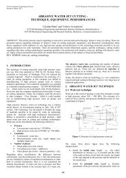
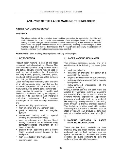
Nonconventional Technologies Review – no.4/ 2008Table 1 Laser marking technologiesP<strong>ro</strong>cess Schema MechanismVaporizationMaterial removal mainlyby vaporizationThin layersmaterialremovalCarbonisationor colorationSurface modifyby materialfusionThin layers materialremoval by cont<strong>ro</strong>lledvaporisation, changingthe colour of the underlayersColour changing byphoto-thermal or photochemicalreactionsDestruction of materialsby py<strong>ro</strong>lyze reactionthat leads to irregularstructures into thematerialIn mask marking (fig 1.a), a stencil of thedesired mark is p<strong>ro</strong>jected onto the workpiece.The picture of the mask on the object is madeusing a lens. Employed in the mask markingare often the pulsed lasers [1], [2], [3].In the beam deflected method (fig. 1.b), thelaser is directed via two galvanometer mir<strong>ro</strong>rsand a lens system to the object to be marked.Using special software, a computer cont<strong>ro</strong>lsthe galvanometer mir<strong>ro</strong>rs. The marking ismade by directing the beam in directions xand y. The beam deflection method is veryflexible and can transmit a high density ofinformation. The lasers used in this methodare often continuous wave lasers.Comparing the two marking methods, it isconcluded that• marking speed: mask marking has highermarking speed up to a few tens piecesper second. Because the laser pulseduration is in the range of mic<strong>ro</strong>-second tonanosecond, the workpiece to be markeddoes not need to stop.• marking area: beam deflected markinghas a bigger marking area. The markingarea by mask marking is very smallbecause of limited beam spot size andenergy per pulse.• flexibility: in mask making, the patternsrequired are p<strong>ro</strong>duced by masks. Top<strong>ro</strong>duce a mask is time-consuming.Therefore, mask marking is more suitablefor high-volume p<strong>ro</strong>duction without anychange on the patterns. In beam deflectedmarking, the patterns are p<strong>ro</strong>duced bysoftware. Thus, it is highly flexible tochange patterns.• cost of investment: in general, the cost ofbeam deflected marking is higherbecause the scanning system is moreexpensive.18
Nonconventional Technologies Review – no.4/ 2008a) The mask marking b) The beam deflected methodFig. 1 Principe of laser marking4. <st<strong>ro</strong>ng>LASER</st<strong>ro</strong>ng> FOR <st<strong>ro</strong>ng>THE</st<strong>ro</strong>ng> <st<strong>ro</strong>ng>MARKING</st<strong>ro</strong>ng> PROCESSThe most popular systems are lamp-pumpedNd:YAG lasers, which p<strong>ro</strong>duce near infraredlight at a wavelength of 1,064 µm, and CO 2lasers, which p<strong>ro</strong>duce light at the 10,64 µmwavelength.Because of their wavelength, Nd: YAG lasersare more capable than CO 2 lasers—but theyare also substantially higher in cost. The1,064-µm wavelength is more easilyabsorbed by a vast range of materials. CO 2lasers are an economical marking solution,as long as the wavelength and materialmatch.The excimer lasers are used in the lasermarking too [4]. Among all laser types, theyassure the highest resolution of the mark.But, these lasers are rarely used because ofthe low p<strong>ro</strong>ductivity of the p<strong>ro</strong>cess and of thevery expensive cost of the laser equipment.Recently, the diode-pumped Nd:YAG lasersare used for the marking p<strong>ro</strong>cess. Theselasers offer high beam quality, excellentpulse-to-pulse stability, and longmaintenance intervals (typically every 12,000to 15,000 hours of use).When selecting a laser marking system for aparticular application there are many factorsto consider [1], [5], [6]:• power density• thermal thermal conductivity19 heat capacity melting point heat of vaporisation• reflectivity material wavelength temperaturePower density is determined by the amount of(peak) power generated by the laser dividedby the area of focused beam. Wavelength,beam divergence and quality of opticsbecome important factors in determining howsmall a beam can be p<strong>ro</strong>duced.The amount of time the laser power isfocused onto the material also has impact onthe ease of marking and depth of penetration.Sometimes, the pulse duration is a key factorin determining which laser can be used.Reflectivity or absorptivity is effected by thetype of material, surface condition (i.e.smooth or <strong>ro</strong>ugh, polish or oxidised),wavelength and surface temperature. Ingeneral, metals absorb a greater percentageof Nd:YAG laser energy than that of carbondioxide laser energy. On the other hand,white paper and most transparent materialsabsorb a great amount of carbon dioxidelaser energy. Some materials such as siliconabsorb the same percentage of energy f<strong>ro</strong>meither laser.For the evaluation of available laser markingsystems in the market for different
Nonconventional Technologies Review – no.4/ 2008applications, the following factors shall befocused:• laser specifications;• optical delivery system;• cont<strong>ro</strong>l system and software;• ease of operation;• manufacturer's performance record;• price.The laser specifications of different types oflasers are different. For CW lasers, the majorspecifications should include wavelength,average laser power, power stability, beamquality factors and Q-switch elementperformance (maximum pulse repetition rate,minimum pulse duration, laser peak power).For pulsed lasers, the specifications shouldinclude wavelength, average laser power,maximum peak power, maximum energy perpulse, pulse repetition rate, pulse duration,pulse-to-pulse stability, and beam qualityfactors.There are many types of optical deliverysystems. For mask marking p<strong>ro</strong>cesses, thesystems may include beam expander,homogeniser, CCD camera and monito<strong>ro</strong>r/and mic<strong>ro</strong>scope, and p<strong>ro</strong>ject lens. Thep<strong>ro</strong>ject lens, together with the beam sizeentering it, determines how big a mark can beobtained per pulse.For beam deflected marking system, thesystem may include beam expander, CCDcamera and monitor or/and mic<strong>ro</strong>scope,scanner, fibber optics, and lens. The lens arevery important in determining focused spotsize, marking field, minimum marked-linewidth and power density on the workpiece.The scanner together with the markingsoftware determines the scanning speed.Cont<strong>ro</strong>l systems and software are verydifferent for different laser marking systems.The cont<strong>ro</strong>l system may include feeding ofworkpiece, cont<strong>ro</strong>l of beam on/off, andinterfaces among computer, laser generator,stage, and p<strong>ro</strong>tection/alarm systems. Themarking software should be easy toimplement in a user's system and to p<strong>ro</strong>gramconveniently.5. <st<strong>ro</strong>ng>MARKING</st<strong>ro</strong>ng> QUALITYCHARACTERISTICSThe quality of a mark is assessed by itslegibility characteristics such as markcontrast, mark width, mark depth, spattering,20and mic<strong>ro</strong>cracks [2], [7], [8]. Thecharacteristics are usually evaluated usingcomplementary techniques such as opticalmic<strong>ro</strong>scopy, ult<strong>ro</strong>sonics mic<strong>ro</strong>scopy, elect<strong>ro</strong>nmic<strong>ro</strong>scopy, surface <strong>ro</strong>ughness measurement,and contrast evaluation devices. Theacceptance of level of each of thesecharacteristics generally depends on themanufacturer's requirements.Mark width refers to the width of the linesegment that forms a character. With themask image marking, the mark width in thecharacters is essentially determined by themask geometry and the lens imaging quality.It can be as small as a few mic<strong>ro</strong>-meters,which can only be read under a mic<strong>ro</strong>scope.In beam deflected marking, the line width ismainly determined by the focused beam spotsize, which varies between 20 - 100 µm.Other parameters such as scanning speed,power density and material p<strong>ro</strong>perties alsoaffect the line width. A toolmaker’smic<strong>ro</strong>scope or Talysurf surface texturemeasuring equipment are used for the linewidth measurement.Marking depth depends on energy density,types of materials and the beam/materialinteraction time. In mask marking, thevaporization depth is often determined by thethickness of paint or oxidation layer. It istypical of a few mic<strong>ro</strong>ns to several tens ofmic<strong>ro</strong>ns.In beam deflected marking, greater depth ofpenetration into the material can be achievedvarying between a few mic<strong>ro</strong>ns to severaltens of a millimeter. A further enhancement ofthe effect on the material can be realized bythe supply of gases such as oxygen orcompressed air, which assist materialremoval.Marking contrast is the visual differencebetween the apparent brightness of themarked surface and unmarked surface of aworkpiece.The sharpness or resolution of the markededges affects the marking contrast. Thisparameter is particularly important in marking“bar code”, as poor edge sharpness may failbar code reader. High peak power or powerdensity p<strong>ro</strong>duces better edge resolution.
Nonconventional Technologies Review – no.4/ 2008Scattering is characterized by the presenceof re-solidified d<strong>ro</strong>plets of surface material inthe marking area. These scattering areundesirable as they distort mark boundaryand p<strong>ro</strong>ducing poor line definition.Visual inspection with an optical mic<strong>ro</strong>scopeis often suffice to evaluate the effect.Mic<strong>ro</strong>cracks are created due to thermalstress generated during laser marking. Themic<strong>ro</strong>cracks affects mechanical p<strong>ro</strong>pertiesand may induce cor<strong>ro</strong>sion in metals.Scanning acoustic mic<strong>ro</strong>scope and scanningelect<strong>ro</strong>n mic<strong>ro</strong>scope can be used fordetection and analysis.Continuity: when pulsed or Q-switched CWlasers are used, the repetition rate affects thecontinuity of the marking. Marking speed isanother key factor. An optical scope is usedto evaluate the effect.6. <st<strong>ro</strong>ng>LASER</st<strong>ro</strong>ng> <st<strong>ro</strong>ng>MARKING</st<strong>ro</strong>ng> APPLICATIONSLasers are used in thousands applications ina wide range of industries, as shown intable 2.Photographic imaging and invisible coding.Lasers can create high-resolution images thatsimulate black-and-white photography. It canalso embed information into that photograph.This is an obvious benefit for manufacturingsecurity cards and for making p<strong>ro</strong>ducttracking information invisible.High-speed marking. Lasers have long beenused in the packaging industry to markp<strong>ro</strong>duction coding and expiration dates, butthe technology is just as ideal for puttingidentifying nomenclature onto parts movingalong a high-speed assembly line. Becauseof their speed, accuracy and flexibility, lasersare a cost-effective alternative to labels inhigh-volume, high-mix settings.Data Matrix codes. Data Matrix is a 2Didentification code that resembles acheckerboard. It offers tremendous datacapacity and built-in er<strong>ro</strong>r correction. DataMatrix has been embraced by the automotiveindustry for direct marking of parts, and it’salso in the ATA2000 specification for theae<strong>ro</strong>space industry.Day and night marking. This concept wasdeveloped to make automotive cont<strong>ro</strong>ls easyto locate in the dark. A black topcoat isapplied to a translucent white substrate. Thelaser removes the coating f<strong>ro</strong>m the substrate,p<strong>ro</strong>ducing clear, white characters that arecrisply defined against a colored backg<strong>ro</strong>und.At night the characters are backlit for easyrecognition.Table 2 Some laser marking applicationsMedical industry Elect<strong>ro</strong>nics compounds Data Matrix codes Publicity objects7. <st<strong>ro</strong>ng>LASER</st<strong>ro</strong>ng>S VS. O<st<strong>ro</strong>ng>THE</st<strong>ro</strong>ng>R <st<strong>ro</strong>ng>TECHNOLOGIES</st<strong>ro</strong>ng>There are many methods of marking parts,including labels, ink systems, mechanicalengraving and embossing, and chemical anddry etching [9]. Each has it’s use, but lasersare g<strong>ro</strong>wing more and more popular (table 3).For metals and other materials, engraving,embossing and other contact p<strong>ro</strong>cesses donot facilitate changeover. Tool wear is alsoan issue.Dry etching requires special blast chambersto cont<strong>ro</strong>l debris. Chemical etching usesdange<strong>ro</strong>us acids and requires costly waste21
Nonconventional Technologies Review – no.4/ 2008disposal. Both etching p<strong>ro</strong>cesses requirescreens to be replaced each time a new markis needed.Table 3 Comparison of laser vs. other marking technologiesMarking p<strong>ro</strong>cess Speed Performance Image flexibilityLaser marking Good Good GoodChemical etch Good Good PoorPhoto etch Good Good PoorInk-jet Good Poor GoodMechanical stamping Good Good PoorPneumatic pin Moderate Good ModerateVibratory pencil Poor Good GoodCONCLUSIONSNowadays, among laser p<strong>ro</strong>cessing methods,laser marking is the most utilised. It assures asuperior quality of marks versus theconventional marking techniques.The need to p<strong>ro</strong>cess materials having specialcharacteristics and the necessity of realizingmic<strong>ro</strong>-p<strong>ro</strong>cessing impose the designing andthe achievement of some technologicalsystems capable to satisfy theserequirements.REFERENCES[1] Alexandru NICHICI s.a., Prelucrarea prine<strong>ro</strong>ziune în construcția de maşini.Editura Facla, Timişoara, 1983.[2] George CHRYSSOLOURIS, Lasermachining, Theory and Practice,Springer-Verlag, New-York, 1991.[3] Adelina HAN, Stadiul actual altehnologiilor laser de prelucrare amaterialelor polimerice, Referat dedoctorat nr. 1; Universitatea „Politehnica”Timişoara, 2002.[4] K. CALLEWAERT s.a., Excimer laserinduced pattering of polymeric surface.Applied Surface Science, Vol. 209, 2003,p. 55-62.[5] T.W, NG, S.C. YEO, Aesthetic lasermarking assessment. Optics and LaserTechnology, Vol. 32, 2000, p, 187–191[6] D.R. ALEXANDRE, M.S. KHLIF, Lasermarking using organo-metallic films.Optic and Laser in Engineering, Vol. 2,1996, p. 55–70.[7] A.D. COMPAAN, I. MATULIONIS, S.NAKADE. Laser scribing ofpolycrystalinne thin films. Optics andLasers in Engineering, 2000, Vol. 34, p.15-45.[8] J. QI, K.L. WANG, Y.M. ZHU, A study onthe marking p<strong>ro</strong>cess of stainless steel.Maretial P<strong>ro</strong>cessing Technology, Vol.139, 2003, p. 273-273.[9] Mihaela NISTORAN-BOTIŞ, DinuGUBENCU, Glass etching, P<strong>ro</strong>ceedingsof the 3 rd International ConferenceRaDMI 2003, 19-23 September 2003,Herceg Novi, Serbia and Monteneg<strong>ro</strong>.AUTHORS1Eng. Adelina HANPolitehnica University of Timisoara, Romania,Email: adealina@yahoo.com,2 PhD Dinu GUBENCUPolitehnica” University of Timisoara, Romania,Email: dinuval@yahoo.com,22