ABRASIVE WATER JET CUTTING - TECHNIQUE ... - Revtn.ro
ABRASIVE WATER JET CUTTING - TECHNIQUE ... - Revtn.ro
ABRASIVE WATER JET CUTTING - TECHNIQUE ... - Revtn.ro
- No tags were found...

Create successful ePaper yourself
Turn your PDF publications into a flip-book with our unique Google optimized e-Paper software.
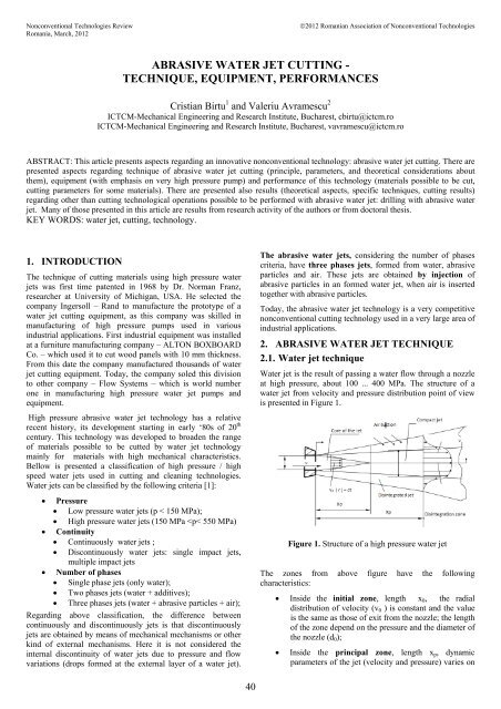
adial and axial directions; hence the velocitydecreases up to value v(x,r) < v 0 and the density of thecore of the jet decreases;• Disintegration zone starts f<strong>ro</strong>m the point where wehave not a core of the jet anymore.In figure 2 it is presented a water jet obtained on aexperimental water jet cutting equipment f<strong>ro</strong>m ICTCM. Thecharacteristics of this water jet are: pressure 230 MPa, nozzlediameter 0.20 mm. In this picture, it can be observed the lengthof the principal zone of the jet, and the disintegration of the jet(dimmed white layer on outside part of the jet) due to injectionand friction with the air.and a water flow of 1.2 l/min, the length of principal zone (x p )is about 90 mm.Force(N)12,51211,51110,51011125153050709011,1111211,511,1 1111 11,2 10,8Distance f<strong>ro</strong>m nozzle exit (mm)Figure 4. Variance of the water jet force withdistance f<strong>ro</strong>m nozzle exit (nozzle diameter 0.2 mm)Figure 2. View of a high pressure water jet (230 MPa)Most important f<strong>ro</strong>m application point of view, is the length ofprincipal zone (x p ), inside which are cut materials.In figure 3, the values experimentally determined arerepresented for water jet force at different pressures. Thevalues are determined using an experimentally device placedperpendicular on jet direction.1510Force (N)507,310 10,5 1190 160 175 200Pump pressure (MPa)Figure 3. Water jet forceExperimental results of a water jet force at different distancesf<strong>ro</strong>m nozzle exit are presented in Figure 4. It can be observedthat, for a nozzle diameter of 0.2 mm, a pressure of 200 MPaThe length x p can be determined int<strong>ro</strong>ducing the water jetlength quotient (k), expressed by the following formula:k = x p / d 0 (1)The authors experimentally determined values for the quotientk measuring the force of different water jets (e. g. in Figures 3and 4). Considering that at the end of principal zone the forceof the water jet decreases with 70%, the authors determined thefollowing experimental values for k quotient. Hence, forpressures in range 170 ... 230 MPa and nozzle diameters of0.15 ... 0.30 mm, the water jet length quotient can bedetermined with the following formula:k 170...230 = 250...520 (2)The velocity of a water jet, considering Bernoulli’s law, can bedetermined by the following formula:v 0= μ ⋅2Pρ( P) (3)- p 1 - pressure before the water exit the nozzle ;- v – water jet velocity at exit point f<strong>ro</strong>m the nozzle;- ρ – density of the water at the pressure p 1;- µ - quotient counting energy looses at input.In Figure 5 it is represented variation of µ quotient withpressure for carbide water nozzles determined by the authorson an experimental water jet equipment presented in nextchapter.Press.[MPa]2502001501005000,75 0,71 0,78 0,93Figure 5. Values for µ quotient (for carbide nozzles)µ41
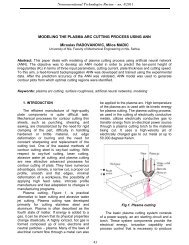
Another specific aspect of high pressure water jets is thedensity of the water. If, for low pressures (up to 100 MPa) thewater is incompressible, at pressures above 150 MPa the wateris compressible. The density of water can be calculated withthe following formula:ρ / ρ 0 = 1 / [1 – ( β ⋅ p)] (4)- p - pressure;- ρ – water density at current pressure;- ρ 0 – water density at atmosphericpressure (0,1 MPa) ;- β – water compressibility module.In formula 4 can be observed that there is a linear dependencebetween density and pressure, if we consider that watercompressibility module β is constant . In fact it is not constantit varies with pressure [2] .In Figure 4 it is presented variation of water density withpressure for two cases:• A gaseous phase represented by the air int<strong>ro</strong>duced influid due to method of int<strong>ro</strong>duction of abrasiveparticles in water jet: injection.The mechanism of abrasive water jet forming it is not up to thismoment theoretically explained due to the big number ofindependent parameters which participate.However, it can be explained the mechanism of a abrasivewater jet forming, as it is represented in figure 7 [3] .• β (water compressibility module) is constant withpressure increase ;• β (water compressibility module) is not constant withpressure increase : it decreases. ;The values are obtained during tests performed on aexperimental water jet equipment in ICTCM laboratory.Looking closer to the values f<strong>ro</strong>m Figure 6 it can beconcluded that, f<strong>ro</strong>m practical point of view, the water densityincreases linear with pressure increase up to 200 MPa, and notlinear for pressures between 200 ... 400 MPa.Densityvariation[%]20151050ß‐const.ß‐var.100 150 200 250 300 350 400Pressure [MPa]Figure 6. Variation of water density vs. pressureConsidering values of water density and µ quotient f<strong>ro</strong>mFigures 3 and 4, the values for velocity of water jet (forpressure between 100 … 450 MPa) calculated with formula 3are:v 0 = 328 ... 786 (m/s) (5)It can be observed that the water jet velocity, for pressures usedfor cutting (200 ... 450 MPa), is grater than the velocity ofsound in air (v s = 347 m/s).2.2. Abrasive water jet techniqueAbrasive water jet is a polyphasic fluid where the constituentsdo not react chemically each other. The phases of this fluid are:• A liquid phase represented by the water (with thelargest mass participation);• A solid phase represented by abrasive particles;Figure 7. Abrasive water jet forming mechanism- 1 – water jet nozzle;- 2 – formed water jet;- 3 – abrasive particle;- 4 – water – abrasive particles focus;- 5 – formed abrasive water jet.The high pressure water jet 2 passes thru a zone called mixingchamber between nozzle 1 exit and entrance in focus 4. In thisarea the pressure is negative due to very high velocity of waterjet.Abrasive particles 3 are sucked in water stream due to thisnegative pressure, in area ranging between points I and II. Inarea between points II and III the abrasive particles are forcedto move in the direction of the water stream, but the velocity ofthem is low. If the abrasive jet should exit f<strong>ro</strong>m focus in pointIII, the velocity is too low and the efficiency should be lowalso.Between points III and IV the abrasive particles velocity isincreased but this will never reaches the velocity of water jet. Ifthe length of this zone is too big, the velocity of particles willbe decreased due to friction with focus walls.Because there are so many parameters, it is difficult totheoretically determine the length of focus 4. Hence the lengthof focus is experimentally determined by the focusmanufacturers, in order to increase as much as possible thevelocity of abrasive particles.Usually the ratio between focus diameter and its length is (25… 50).In figure 8 is presented an abrasive water jet cutting head f<strong>ro</strong>man experimental equipment of ICTCM.Similar to water jet, it was determined the force of an abrasivewater jet (the experimental device is similar).Comparatively (see Figure 9), the forces of a water jet (WJ)and abrasive water jet (AWJ) do not vary too much.42
Keeping identical values for common parameters (pressure,water flow, nozzle diameter) the authors determinedexperimental values for these forces.Figure 8. Abrasive water jet cutting head (ICTCM)Hence, for a pressure of 200 MPa, water flow of 1.2 l/min anda nozzle diameter of 0.2 mm, the experimental values forforces are:F WJ = (10.8 ... 12.0) N (6)F AWJ = (7.0 ... 8.0) N (7)It can be observed that the force of a water jet is 35 ... 36 %bigger than an abrasive water jet.Regarding the variance of jet force with the distance f<strong>ro</strong>m exitpoint, the force is constant in principal zone for AWJ also. InFigure 9 bellow are represented the forces for water jet andabrasive water jet as described above. It can be observed that,for different diameters of focus the force of abrasive water jetincreases slightly.15Force 10[N] 50p = 200 MPa10 15 20Distance [mm]0,8mm1,0mmapaFigure 9. Comparison of AWJ and WJ forcesFigure 10. Abrasive water jet cutting equipment (ICTCM)Low pressure hydraulic g<strong>ro</strong>up has the following technicalcharacteristics:• Working pressure: 20 MPa;• Maximum pressure: 31.5 MPa;• Oil flow: Q = 60 l/min;• Oil tank capacity: 500 l;• Electric motor:• Power 22 kW;• Speed 1000 r/min.High pressure g<strong>ro</strong>up increases the pressure of water f<strong>ro</strong>msupply pressure to working high pressure. The main part of thisg<strong>ro</strong>up is high pressure pump / amplifier.In Figure 10 it can be observed that the equipment has two highpressure pumps which can work together or individually. Thereare components which are parts of high pressure g<strong>ro</strong>up: checkvalves, a safety valve, hydraulic accumulator, filters.The high pressure g<strong>ro</strong>up has the following technicalcharacteristics:• Maximum pressure: 400 MPa;• Water flow: 1.2 l/min;• Amplification ratio: 34:1;• Nominal diameter: 2.0 mm;• Filtration finesse: 15 µm.The equipment has also a high pressure measuring systemwhich has as main part a high pressure sensor connected with adata acquisition system.3. <st<strong>ro</strong>ng>ABRASIVE</st<strong>ro</strong>ng> <st<strong>ro</strong>ng>WATER</st<strong>ro</strong>ng> <st<strong>ro</strong>ng>JET</st<strong>ro</strong>ng> <st<strong>ro</strong>ng>CUTTING</st<strong>ro</strong>ng>(EXPERIMENTAL) EQUIPMENTExperimental results presented in this paper are obtained f<strong>ro</strong>ma cutting equipment presented in Figure 10 bellow.The equipment is composed f<strong>ro</strong>m 2 main functionalassemblies:• low pressure hydraulic g<strong>ro</strong>up• high pressure g<strong>ro</strong>up.4. PERFORMANCES OF <st<strong>ro</strong>ng>ABRASIVE</st<strong>ro</strong>ng> <st<strong>ro</strong>ng>WATER</st<strong>ro</strong>ng><st<strong>ro</strong>ng>JET</st<strong>ro</strong>ng> <st<strong>ro</strong>ng>CUTTING</st<strong>ro</strong>ng> TECHNOLOGY4.1. Abrasive water jet cuttingAbrasive water jet cutting p<strong>ro</strong>cess is influenced by manyspecific parameters which influence quality, efficiency and thecost of p<strong>ro</strong>cess [4].The influence parameters of the abrasive water jet p<strong>ro</strong>cessingare:a. P<strong>ro</strong>cess parameters (specific to AWJ p<strong>ro</strong>cessing);43
. Result/effect parameters (describe the effect ofabrasive water jet on workpiece).P<strong>ro</strong>cess parameters are:• Hydraulic parameters: pump pressure, nozzlediameter, water flow;• P<strong>ro</strong>cessing parameters: cutting speed, number ofpasses, cutting distance (between focus tube tip – cutpiece);• Abrasive particles mixing and accelerationparameters: focus inner diameter and length;• Abrasive particles specific parameters: mass flow,diameter/dimension off abrasive particle, hardness,shape.Result parameters express the result of p<strong>ro</strong>cessing; they arethe following (see Figure 11):• Cut width in upper zone of the workpiece (bs);• Cut width in down zone of the workpiece (bi);• Cut tilt (It);• Angle of the flank (φ F );• Smooth zone high (h a );• Wavy zone high (h v )Figure 12-b. Stainless steel (6 mm) and marble(20 mm) cut with AWJIn figures bellow there are presented influence of somep<strong>ro</strong>cess parameters on cut efficiency, mainly on cut depth.In Figure 13 it is presented the influence of pressure e onp<strong>ro</strong>cess efficiency. It can be observed that the efficiency of thep<strong>ro</strong>cess, represented by the cut depth, increases with increaseof pressure, regardless the material.Figure 11. Geometry of AWJ cutIn Table 1 are presented results of materials cut with abrasivewater jet on the experimental equipment f<strong>ro</strong>m Figure 10.In figure 12 (a, b) there are presented examples of materials cutwith abrasive water jet.Cutdepth[mm]40200AlGlass175 190 200 210 230Pressure [MPa]Figure 13. Influence of pressure on p<strong>ro</strong>cess efficiencyIn Figure 14 it is presented the influence of cutting speed onp<strong>ro</strong>cess efficiency. It can be observed that an increase incutting speed decrease the cut depth hence the p<strong>ro</strong>cessefficiency.AlGlassCut50depth0[mm]20 25 35 44 55 65 75Cut speed [mm/min]Figure 12-a. – Stone, granite and marblecut with AWJFigure 14. Influence of cutting speed on p<strong>ro</strong>cess efficiency44
Figure 15 shows the influence of distance between focus tubeand part to be cut on p<strong>ro</strong>cess efficiency. General influence is todecrease the p<strong>ro</strong>cess efficiency with increase of distance almostlinear.• d sup – upper diameter of the hole• d inf – lower diameter of the hole• h – hole depth.AlGlassAluminiumCut50depth0[mm]5 10 15 20 25 30Distantance to piece [mm]SteelGlassFigure 15. Influence of distance focus - piece on p<strong>ro</strong>cessefficiency4.2. Abrasive water jet drillingAbrasive water jet drilling is the p<strong>ro</strong>cess in which neither thecutting head nor the working part move relative each other.The abrasive jet penetrates totally the working part.The drilling p<strong>ro</strong>cess has three phases [5, 8]:• Impact phase (during abrasive waterjet input in piecematerial);• Penetration phase when there are inverse flows ofwater near the hole walls until complete penetration ofthe hole;• Finishing phase, when the hole walls are finished untilfinish of p<strong>ro</strong>cess.In Figure 16 it is presented the geometry of a hole drilled withabrasive water jet.Figure 17. – Examples of materials drilled with AWJIn figure 17, there are presented examples of materials drilledwith abrasive water jet: steel, aluminium and glass.In table 2, are presented results of abrasive water jet drilling ofmaterials f<strong>ro</strong>m figure 17.Figure 18 presents the influence of material on two of mainparameters of abrasive water jet drilling:• specific volume of material excavated by the abrasivewater jet Vc (mm 3 /s);• the taper of the hole k (°).The conclusions of the curves presented in figure 18 are:• specific volume decreases with increase of tensilestrength of drilled material;• the hole taper is dependent of material toughness; forexample for glass the taper is very low as it is a brittlematerial.Figure 16. Geometry of AWJ drilled holeWe have for the parameters f<strong>ro</strong>m figure the followingmeanings:• d i – equivalent diameter of the impact zone;8-Vol.spec. 6[mmc/s] 4-Conicit.2[grd]0Specificvolume(Vg)[mm 3 /s]Taper(k) [deg]VgSteel Al GlasskMaterial.Figure 18. Influence of material characteristics on specificvolume excavated and taper of the hole (ICTCM)45
MaterialThicknessTable 1. Materials cut with abrasive water jet (ICTCM)CuttingspeedCutwidth Cut quality TechnologicalaspectsFlank aspect Roughness- (mm) (cm/min) (mm) - - -5 8,0 1,5 Clean, without Smooth at jetAluminium 6 7,0 1,5 cracks, <strong>ro</strong>unded entranceAlCu 4 MgMn ∅20 4,5 2,5 at jet entranceAs for aluminiumBrass 3,0 8,5 1,5(Cu Zn 37)∅25 3,7 3,0B<strong>ro</strong>nze∅25 4,5 3,5 Smooth, <strong>ro</strong>und at(Cu Sn 14)Structural Steel(St37)2,0 7,84,0 6 2,26,0 5,5∅ 6 6,1 3,0∅ 12 4,8jet entranceGood, flankswithout cracksB<strong>ro</strong>ken flanksAs for aluminiumSmooth, nowavesBetter for upperzone of the cutThe cutting speedcan be increasedIn decrease thespeed increasethe quality offlanksStainless 1,25 6,5Flanks with smallsteel 2,0 6,0 2,5 cracksGood(15 Cr 170) 2,5 5,8Alloyed steel ∅ 20 3,0 1,8 B<strong>ro</strong>ken flanks Rough Hard to be cut(41MoCr11)MaterialThicknessTable 2. Materials drilled with abrasive water jet (ICTCM)DistancefocuspieceSpecificvolumeexcavatedGeometric parameters of the holeObservationsV g k d sup d inf- (mm) (mm) (mm 3 / s) ( °) (mm) (mm) -Glass 5,0 6 5,426 0 3,215 2,265 - pressure 200 MPa;- mixing tube:Aluminium 10,0 3,0 1,6 0,444 0 2,085 1,930 - d t = 0,8 mm;- l t = 42 mm.Structuralsteel(St 37)5. CONCLUSIONS5,0 0,9 5,653 0 2,915 1,925 - abrasive flow: 4,66g/s;- abrasive: garnet withdiameter 100...160 μmThe work presented in this paper is done at ICTCM Buchareston experimental abrasive water jet equipment. This researchwork had the purpose to identify, as much as possible, specificaspects of the technology, equipment and phenomena of thistechnology.It served to further developments of both equipment andtechnology, in order to identify all possible applications of thistechnology in different industries.6. REFERENCES1. Momber, A., Statistical character of the failure of <strong>ro</strong>cklikematerials due to high energy of water impingement,International Journal of Fracture, no. 71 / (1995).2. Przyklenk, K., Gezieltes Entgraten metallischerWerkstücke durch Hochdruckwasserstrahlen,Kernforschungzentrum Karlsruhe, Germany, (1985).3. Hashish, M., Prediction Models for AWJ MachiningOperations, 7th American Waterjet Conference, Seattle,Washington, (1993).4. Hashish, M., Visualisation of abrasive water jet cuttingp<strong>ro</strong>cess, Experimental mechanics, no. 28/(1988).5. Hashish, M., Precision drilling of ceramic-coatedcomponents with abrasive waterjet, Journal ofEngineering for Gas, Turbines and Power, Jan. (1993)6. Hashish, M., Pressure effects in abrasive water jetmachining, Journal of Engineering Materials andTechnology, vol. 111. (1989).7. Kitamura, M., Developments of waterjet cuttingtechnology for steam turbine components, QuarterlyJournal of the Japan Welding Society, Vol. 11, No. 3,(1993).8. Geskin, E, S, Waterjet cutting experiments determineoptimal techniques. Research finds methods to imp<strong>ro</strong>vesurface and cut qualities, Glass Digest, (1988).9. Birtu, C., Contributions to technology and equipment ofabrasive water jet manufacturing of materials, PhD.Thesis, Polytechnic University of Bucharest, (2000).46