modeling the plasma arc cutting process using ann - Revtn.ro
modeling the plasma arc cutting process using ann - Revtn.ro
modeling the plasma arc cutting process using ann - Revtn.ro

Create successful ePaper yourself
Turn your PDF publications into a flip-book with our unique Google optimized e-Paper software.
Nonconventional Technologies Review – no. 4/2011<br />
MODELING THE PLASMA ARC CUTTING PROCESS USING ANN<br />
Mi<strong>ro</strong>slav RADOVANOVIC, Milos MADIC<br />
University of Nis, Faculty of Mechanical Engineering in Nis, Serbia<br />
Abstract: This paper deals with <st<strong>ro</strong>ng>modeling</st<strong>ro</strong>ng> of <st<strong>ro</strong>ng>plasma</st<strong>ro</strong>ng> <st<strong>ro</strong>ng>cutting</st<strong>ro</strong>ng> <st<strong>ro</strong>ng>p<strong>ro</strong>cess</st<strong>ro</strong>ng> <st<strong>ro</strong>ng>using</st<strong>ro</strong>ng> artificial neural network<br />
(ANN). The objective was to develop an ANN model in order to predict <st<strong>ro</strong>ng>the</st<strong>ro</strong>ng> ten-point height of<br />
irregularities (R z ) in terms of three input parameters, <st<strong>ro</strong>ng>cutting</st<strong>ro</strong>ng> current, plate thickness and <st<strong>ro</strong>ng>cutting</st<strong>ro</strong>ng> speed.<br />
To this aim, a feed-forward backp<strong>ro</strong>pagation ANN was developed and trained <st<strong>ro</strong>ng>using</st<strong>ro</strong>ng> <st<strong>ro</strong>ng>the</st<strong>ro</strong>ng> experimental<br />
data. After <st<strong>ro</strong>ng>the</st<strong>ro</strong>ng> prediction accuracy of <st<strong>ro</strong>ng>the</st<strong>ro</strong>ng> ANN was validated, ANN model was used to generate<br />
contour plots f<strong>ro</strong>m which optimal <st<strong>ro</strong>ng>cutting</st<strong>ro</strong>ng> regions were identified.<br />
Keywords: <st<strong>ro</strong>ng>plasma</st<strong>ro</strong>ng> <st<strong>ro</strong>ng>arc</st<strong>ro</strong>ng> <st<strong>ro</strong>ng>cutting</st<strong>ro</strong>ng>, surface <strong>ro</strong>ughness, artificial neural networks, <st<strong>ro</strong>ng>modeling</st<strong>ro</strong>ng><br />
1. INTRODUCTION<br />
The efficient manufacture of high-quality<br />
plate components is quite difficult task.<br />
Mechanical <st<strong>ro</strong>ng>p<strong>ro</strong>cess</st<strong>ro</strong>ng>es for contour <st<strong>ro</strong>ng>cutting</st<strong>ro</strong>ng> thin<br />
sheets, such as punching, shearing, and<br />
sawing, are characterized by <st<strong>ro</strong>ng>the</st<strong>ro</strong>ng> need for rigid<br />
clamping of <st<strong>ro</strong>ng>the</st<strong>ro</strong>ng> part, difficulty in handling<br />
hardened or brittle material, cut edge<br />
deformation or burring and <st<strong>ro</strong>ng>the</st<strong>ro</strong>ng> need for<br />
constant sharpening and replacement of <st<strong>ro</strong>ng>the</st<strong>ro</strong>ng><br />
<st<strong>ro</strong>ng>cutting</st<strong>ro</strong>ng> tool. One of <st<strong>ro</strong>ng>the</st<strong>ro</strong>ng> easiest methods of<br />
contour <st<strong>ro</strong>ng>cutting</st<strong>ro</strong>ng> steel is oxy-fuel <st<strong>ro</strong>ng>cutting</st<strong>ro</strong>ng>. With<br />
respect to oxy-fuel <st<strong>ro</strong>ng>cutting</st<strong>ro</strong>ng>, laser <st<strong>ro</strong>ng>cutting</st<strong>ro</strong>ng>,<br />
abrasive water jet <st<strong>ro</strong>ng>cutting</st<strong>ro</strong>ng>, and <st<strong>ro</strong>ng>plasma</st<strong>ro</strong>ng> <st<strong>ro</strong>ng>cutting</st<strong>ro</strong>ng><br />
are new attractive advanced <st<strong>ro</strong>ng>p<strong>ro</strong>cess</st<strong>ro</strong>ng>es for<br />
contour <st<strong>ro</strong>ng>cutting</st<strong>ro</strong>ng> of plate. They have nume<strong>ro</strong>us<br />
advantages, namely, a nar<strong>ro</strong>w cut, a p<strong>ro</strong>per cut<br />
p<strong>ro</strong>file, smooth and flat edges, minimal<br />
deformation of a workpiece, <st<strong>ro</strong>ng>the</st<strong>ro</strong>ng> possibility of<br />
applying high feed rates, intricate p<strong>ro</strong>file<br />
manufacture and fast adaptation to changes in<br />
manufacturing p<strong>ro</strong>grams.<br />
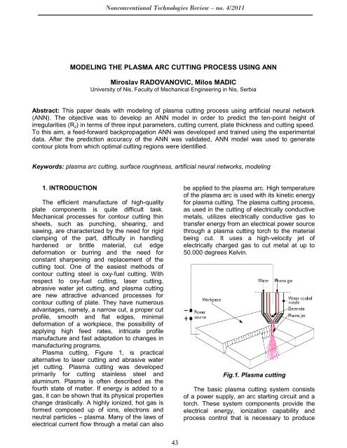
Plasma <st<strong>ro</strong>ng>cutting</st<strong>ro</strong>ng>, Figure 1, is practical<br />
alternative to laser <st<strong>ro</strong>ng>cutting</st<strong>ro</strong>ng> and abrasive water<br />
jet <st<strong>ro</strong>ng>cutting</st<strong>ro</strong>ng>. Plasma <st<strong>ro</strong>ng>cutting</st<strong>ro</strong>ng> was developed<br />
primarily for <st<strong>ro</strong>ng>cutting</st<strong>ro</strong>ng> stainless steel and<br />
aluminum. Plasma is often described as <st<strong>ro</strong>ng>the</st<strong>ro</strong>ng><br />
fourth state of matter. If energy is added to a<br />
gas, it can be shown that its physical p<strong>ro</strong>perties<br />
change drastically. A highly ionized, hot gas is<br />
formed composed up of ions, elect<strong>ro</strong>ns and<br />
neutral particles – <st<strong>ro</strong>ng>plasma</st<strong>ro</strong>ng>. Many of <st<strong>ro</strong>ng>the</st<strong>ro</strong>ng> laws of<br />
electrical current flow th<strong>ro</strong>ugh a metal can also<br />
be applied to <st<strong>ro</strong>ng>the</st<strong>ro</strong>ng> <st<strong>ro</strong>ng>plasma</st<strong>ro</strong>ng> <st<strong>ro</strong>ng>arc</st<strong>ro</strong>ng>. High temperature<br />
of <st<strong>ro</strong>ng>the</st<strong>ro</strong>ng> <st<strong>ro</strong>ng>plasma</st<strong>ro</strong>ng> <st<strong>ro</strong>ng>arc</st<strong>ro</strong>ng> is used with its kinetic energy<br />
for <st<strong>ro</strong>ng>plasma</st<strong>ro</strong>ng> <st<strong>ro</strong>ng>cutting</st<strong>ro</strong>ng>. The <st<strong>ro</strong>ng>plasma</st<strong>ro</strong>ng> <st<strong>ro</strong>ng>cutting</st<strong>ro</strong>ng> <st<strong>ro</strong>ng>p<strong>ro</strong>cess</st<strong>ro</strong>ng>,<br />
as used in <st<strong>ro</strong>ng>the</st<strong>ro</strong>ng> <st<strong>ro</strong>ng>cutting</st<strong>ro</strong>ng> of electrically conductive<br />
metals, utilizes electrically conductive gas to<br />
transfer energy f<strong>ro</strong>m an electrical power source<br />
th<strong>ro</strong>ugh a <st<strong>ro</strong>ng>plasma</st<strong>ro</strong>ng> <st<strong>ro</strong>ng>cutting</st<strong>ro</strong>ng> torch to <st<strong>ro</strong>ng>the</st<strong>ro</strong>ng> material<br />
being cut. It uses a high-velocity jet of<br />
electrically charged gas to cut metal at up to<br />
50.000 degrees Kelvin.<br />
Fig.1. Plasma <st<strong>ro</strong>ng>cutting</st<strong>ro</strong>ng><br />
The basic <st<strong>ro</strong>ng>plasma</st<strong>ro</strong>ng> <st<strong>ro</strong>ng>cutting</st<strong>ro</strong>ng> system consists<br />
of a power supply, an <st<strong>ro</strong>ng>arc</st<strong>ro</strong>ng> starting circuit and a<br />
torch. These system components p<strong>ro</strong>vide <st<strong>ro</strong>ng>the</st<strong>ro</strong>ng><br />
electrical energy, ionization capability and<br />
<st<strong>ro</strong>ng>p<strong>ro</strong>cess</st<strong>ro</strong>ng> cont<strong>ro</strong>l that is necessary to p<strong>ro</strong>duce<br />
43
Nonconventional Technologies Review – no. 4/2011<br />
high quality, highly p<strong>ro</strong>ductive cuts on a variety<br />
of different materials. Plasma <st<strong>ro</strong>ng>cutting</st<strong>ro</strong>ng> can be<br />
used to cut plate to 180 mm thick. Plasma<br />
<st<strong>ro</strong>ng>cutting</st<strong>ro</strong>ng> is less expensive than laser <st<strong>ro</strong>ng>cutting</st<strong>ro</strong>ng>.<br />
Nit<strong>ro</strong>gen based systems are well suited for high<br />
performance materials such as stainless steel,<br />
aluminum and nickel. Oxygen based systems<br />
are better for carbon steels and leave no nitride<br />
deposits, which complicate fur<st<strong>ro</strong>ng>the</st<strong>ro</strong>ng>r <st<strong>ro</strong>ng>p<strong>ro</strong>cess</st<strong>ro</strong>ng>ing.<br />
Plasma consumables can be short lived<br />
depending on gas selection, operator<br />
p<strong>ro</strong>ficiency and water selection. Heat affected<br />
zones appear in <st<strong>ro</strong>ng>the</st<strong>ro</strong>ng> area sur<strong>ro</strong>unding <st<strong>ro</strong>ng>the</st<strong>ro</strong>ng> cut.<br />
D<strong>ro</strong>ss can occur. Under water <st<strong>ro</strong>ng>cutting</st<strong>ro</strong>ng> helps<br />
reduce <st<strong>ro</strong>ng>the</st<strong>ro</strong>ng> size of <st<strong>ro</strong>ng>the</st<strong>ro</strong>ng> heat affected zone. Fine<br />
<st<strong>ro</strong>ng>plasma</st<strong>ro</strong>ng> <st<strong>ro</strong>ng>cutting</st<strong>ro</strong>ng> (high tolerance <st<strong>ro</strong>ng>plasma</st<strong>ro</strong>ng> <st<strong>ro</strong>ng>arc</st<strong>ro</strong>ng><br />
<st<strong>ro</strong>ng>cutting</st<strong>ro</strong>ng>) is used for <st<strong>ro</strong>ng>cutting</st<strong>ro</strong>ng> metals f<strong>ro</strong>m 5 to 10<br />
mm thickness. This system uses a nozzle with<br />
a smaller orifice diameter so <st<strong>ro</strong>ng>the</st<strong>ro</strong>ng> flow rate of <st<strong>ro</strong>ng>the</st<strong>ro</strong>ng><br />
spinning <st<strong>ro</strong>ng>plasma</st<strong>ro</strong>ng> gas is much higher. The cut<br />
quality is nearly as good as laser <st<strong>ro</strong>ng>cutting</st<strong>ro</strong>ng>, but at<br />
a lower cost.<br />
2. ARTIFICIAL NEURAL NETWORKS:<br />
AN OVERVIEW<br />
The appearance of ANNs is related to <st<strong>ro</strong>ng>the</st<strong>ro</strong>ng><br />
attempt to form an artificial system based on<br />
ma<st<strong>ro</strong>ng>the</st<strong>ro</strong>ng>matical models which will be, in its<br />
structure, function and information (signal)<br />
<st<strong>ro</strong>ng>p<strong>ro</strong>cess</st<strong>ro</strong>ng>ing, similar to biological nervous<br />
systems, and thus be able to <st<strong>ro</strong>ng>p<strong>ro</strong>cess</st<strong>ro</strong>ng><br />
“intelligently” information (signals), that is,<br />
simulate biological intelligence [2].<br />
ANNs consist of a larger number of<br />
neu<strong>ro</strong>ns (as basic <st<strong>ro</strong>ng>p<strong>ro</strong>cess</st<strong>ro</strong>ng>ing units) distributed<br />
in several layers. Each ANN usually have three<br />
layers: input layer, hidden layer, and output<br />
layer. The greatest number of ANNs used for<br />
<st<strong>ro</strong>ng>modeling</st<strong>ro</strong>ng> machining <st<strong>ro</strong>ng>p<strong>ro</strong>cess</st<strong>ro</strong>ng>es have one or<br />
two hidden layers though <st<strong>ro</strong>ng>the</st<strong>ro</strong>ng>re may be more of<br />
<st<strong>ro</strong>ng>the</st<strong>ro</strong>ng>m. Neu<strong>ro</strong>ns of one layer are connected by<br />
specific synapses to <st<strong>ro</strong>ng>the</st<strong>ro</strong>ng> neu<strong>ro</strong>ns of <st<strong>ro</strong>ng>the</st<strong>ro</strong>ng>ir<br />
neighboring layers. Apart f<strong>ro</strong>m specific types of<br />
ANNs, <st<strong>ro</strong>ng>the</st<strong>ro</strong>ng>re are no interconnections between<br />
<st<strong>ro</strong>ng>the</st<strong>ro</strong>ng> neu<strong>ro</strong>ns belonging to <st<strong>ro</strong>ng>the</st<strong>ro</strong>ng> same layer. The<br />
interconnections between particular neu<strong>ro</strong>ns by<br />
<st<strong>ro</strong>ng>the</st<strong>ro</strong>ng> layers are characterized by weights, which<br />
change during <st<strong>ro</strong>ng>the</st<strong>ro</strong>ng> ANN training. By tuning a<br />
set of weights and biases in <st<strong>ro</strong>ng>the</st<strong>ro</strong>ng> training<br />
<st<strong>ro</strong>ng>p<strong>ro</strong>cess</st<strong>ro</strong>ng>, ANN learns <st<strong>ro</strong>ng>the</st<strong>ro</strong>ng> relationship between<br />
given inputs and related outputs.<br />
The ANN based <st<strong>ro</strong>ng>modeling</st<strong>ro</strong>ng> is not a straightforward<br />
<st<strong>ro</strong>ng>p<strong>ro</strong>cess</st<strong>ro</strong>ng> and nume<strong>ro</strong>us decisions<br />
related to ANN <st<strong>ro</strong>ng>arc</st<strong>ro</strong>ng>hitecture and training<br />
<st<strong>ro</strong>ng>p<strong>ro</strong>cess</st<strong>ro</strong>ng>es have to be made. The methodology<br />
and basic steps in ANN <st<strong>ro</strong>ng>modeling</st<strong>ro</strong>ng> of machining<br />
<st<strong>ro</strong>ng>p<strong>ro</strong>cess</st<strong>ro</strong>ng>es and derivation of ma<st<strong>ro</strong>ng>the</st<strong>ro</strong>ng>matical<br />
equations f<strong>ro</strong>m ANNs is presented in [3,4].<br />
After selecting <st<strong>ro</strong>ng>the</st<strong>ro</strong>ng> ANN <st<strong>ro</strong>ng>arc</st<strong>ro</strong>ng>hitecture and<br />
adopting <st<strong>ro</strong>ng>the</st<strong>ro</strong>ng> ANN with <st<strong>ro</strong>ng>the</st<strong>ro</strong>ng> best performance<br />
achieved during training and testing, created<br />
ANN may be used for simulation, prediction or<br />
can be used as a objective function for<br />
optimization.<br />
3. MODELING THE PAC PROCESS<br />
The objective of <st<strong>ro</strong>ng>the</st<strong>ro</strong>ng> <st<strong>ro</strong>ng>plasma</st<strong>ro</strong>ng> <st<strong>ro</strong>ng>arc</st<strong>ro</strong>ng> <st<strong>ro</strong>ng>cutting</st<strong>ro</strong>ng><br />
(PAC) <st<strong>ro</strong>ng>p<strong>ro</strong>cess</st<strong>ro</strong>ng> is to concentrate a large<br />
amount of energy on a small surface of a<br />
workpiece which leads to intensive heating of<br />
<st<strong>ro</strong>ng>the</st<strong>ro</strong>ng> material surface. The source of energy is<br />
high temperature and high speed ionised gas.<br />
The gas is ionised <st<strong>ro</strong>ng>using</st<strong>ro</strong>ng> a direct current<br />
passing between <st<strong>ro</strong>ng>the</st<strong>ro</strong>ng> cathode (inside <st<strong>ro</strong>ng>the</st<strong>ro</strong>ng><br />
nozzle) and anode (workpiece). The <st<strong>ro</strong>ng>plasma</st<strong>ro</strong>ng> jet<br />
cuts <st<strong>ro</strong>ng>the</st<strong>ro</strong>ng> material by releasing <st<strong>ro</strong>ng>the</st<strong>ro</strong>ng> energy spent<br />
for <st<strong>ro</strong>ng>the</st<strong>ro</strong>ng> <st<strong>ro</strong>ng>plasma</st<strong>ro</strong>ng> gas ionisation upon hitting <st<strong>ro</strong>ng>the</st<strong>ro</strong>ng><br />
workpiece surface. The removal of <st<strong>ro</strong>ng>the</st<strong>ro</strong>ng> melted<br />
material f<strong>ro</strong>m <st<strong>ro</strong>ng>the</st<strong>ro</strong>ng> <st<strong>ro</strong>ng>cutting</st<strong>ro</strong>ng> zone is done by <st<strong>ro</strong>ng>the</st<strong>ro</strong>ng><br />
action of <st<strong>ro</strong>ng>plasma</st<strong>ro</strong>ng> jet kinetic energy. The<br />
characteristics of <st<strong>ro</strong>ng>plasma</st<strong>ro</strong>ng> jet can be<br />
significantly altered by changing <st<strong>ro</strong>ng>the</st<strong>ro</strong>ng> type of<br />
gas, gas flow, <st<strong>ro</strong>ng>cutting</st<strong>ro</strong>ng> current, and nozzle size,<br />
etc.<br />
Even though it is <st<strong>ro</strong>ng>the</st<strong>ro</strong>ng> case of a complex<br />
<st<strong>ro</strong>ng>p<strong>ro</strong>cess</st<strong>ro</strong>ng>, which is characterized by a large<br />
number of influential factors, <st<strong>ro</strong>ng>the</st<strong>ro</strong>ng> previous<br />
analysis has shown that this number can be<br />
reduced to three main influential factors: <st<strong>ro</strong>ng>cutting</st<strong>ro</strong>ng><br />
current (I), <st<strong>ro</strong>ng>cutting</st<strong>ro</strong>ng> speed (V), and plate<br />
thickness (s). Influential factors were varied on<br />
a great number of levels. The ten-point height<br />
of irregularities (R z ), which is one of <st<strong>ro</strong>ng>the</st<strong>ro</strong>ng> basic<br />
characteristics of <st<strong>ro</strong>ng>the</st<strong>ro</strong>ng> surface quality, was<br />
selected as <st<strong>ro</strong>ng>the</st<strong>ro</strong>ng> target function (output value).<br />
The experiment was described in more detail in<br />
[1] and experimental data are given in Table 1.<br />
44
Nonconventional Technologies Review – no. 4/2011<br />
Table 1 Data for training and testing of<br />
<st<strong>ro</strong>ng>the</st<strong>ro</strong>ng> ANN<br />
No<br />
Cutting<br />
current<br />
I (A)<br />
Plate<br />
thickness<br />
s (mm)<br />
Cutting<br />
speed<br />
V(m/min)<br />
Surface<br />
<strong>ro</strong>ughness<br />
R z (μm)<br />
1. 80 4 1.3 2.13<br />
2. 80 4 1.4 2.15<br />
3. 80 4 1 2.25<br />
4. 80 4 0.9 2.3<br />
5. 80 4 1.2 2.4<br />
6. 80 4 1.7 2.42<br />
7. 80 4 2.1 3.2<br />
8. 80 4 2.2 3.15<br />
9. 80 4 2.3 3.4<br />
10. 80 4 2.4 3.5<br />
11. 80 4 2.5 3.55<br />
12. 80 4 2.6 3.58<br />
13. 80 4 2.8 3.7<br />
14. 45 4 1.05 3.2<br />
15. 45 4 1.1 3.4<br />
16. 45 4 1.15 3.6<br />
17. 45 4 1.2 3.67<br />
18. 45 4 1.25 4.1<br />
19. 45 4 0.95 3.4<br />
20. 45 4 0.9 3.5<br />
21. 45 4 0.85 3.3<br />
22. 45 4 0.8 3.1<br />
23. 45 4 1.1 3.5<br />
24. 45 4 1.3 3.82<br />
25. 45 4 1.4 3.8<br />
26. 45 4 1.5 4<br />
27. 80 6 1.225 2.15<br />
28. 80 6 1.275 2.21<br />
29. 80 6 1.3 2.25<br />
30. 80 6 1.375 2.25<br />
31. 80 6 1.425 2.28<br />
32. 80 6 1.475 2.3<br />
33. 80 6 1.175 2.22<br />
34. 80 6 1.125 2.35<br />
35. 80 6 1.075 2.35<br />
36. 80 6 1.025 2.38<br />
37. 80 6 0.9 2.45<br />
38. 80 6 1.7 2.5<br />
39. 80 6 1.9 2.6<br />
40. 80 6 2.1 2.65<br />
41. 80 6 2.3 2.8<br />
42. 45 6 0.85 2.55<br />
43. 45 6 0.9 2.48<br />
44. 45 6 1 3.1<br />
45. 45 6 1.1 3.15<br />
46. 45 6 0.8 3.1<br />
47. 45 6 0.75 3.05<br />
48. 45 6 0.7 2.9<br />
49. 45 6 0.65 2.6<br />
50. 45 6 0.6 2.52<br />
51. 45 6 1.300 3.1<br />
52. 80 8 0.9 3.29<br />
53. 80 8 0.95 3.42<br />
54. 80 8 1 3.3<br />
55. 80 8 1.05 3.25<br />
56. 80 8 1.1 3.2<br />
57. 80 8 1.15 3.2<br />
58. 80 8 1.2 3.3<br />
59. 80 8 1.25 3.42<br />
60. 80 8 1.3 3.6<br />
61. 80 8 1.35 4.05<br />
62. 80 8 1.4 4.22<br />
63. 80 8 1.5 4.32<br />
64. 80 8 1.7 4.3<br />
65. 80 8 2 4.5<br />
66. 130 12 0.82 1.79<br />
67. 130 12 0.87 1.85<br />
68. 130 12 0.92 1.86<br />
69. 130 12 0.97 1.9<br />
70. 130 12 1.02 2.06<br />
71. 130 12 1.07 2.22<br />
72. 130 12 0.77 2.1<br />
73. 130 12 0.72 2.15<br />
74. 130 12 0.67 2.12<br />
75. 130 12 0.62 2.2<br />
76. 130 12 0.57 2.25<br />
77. 130 12 1.2 2.1<br />
78. 130 12 1.4 2.18<br />
79. 130 12 1.6 2.2<br />
80. 130 12 1.8 2.27<br />
81. 130 15 0.58 2.16<br />
82. 130 15 0.63 2.2<br />
83. 130 15 0.68 2.22<br />
84. 130 15 0.73 2.3<br />
85. 130 15 0.78 2.42<br />
86. 130 15 0.83 3.05<br />
87. 130 15 0.53 2.2<br />
88. 130 15 0.48 2.42<br />
89. 130 15 0.43 2.62<br />
90. 130 15 0.38 3.23<br />
91. 130 15 0.33 3.78<br />
92. 130 15 0.9 3.15<br />
93. 130 15 1.1 3.1<br />
94. 130 15 1.3 3.05<br />
95. 130 15 1.6 2.5<br />
96. 130 15 1.7 2.25<br />
The series of 29 input-out data for ANN testing is<br />
marked with bold numbers<br />
3.1. ANN design and training<br />
In this paper, <st<strong>ro</strong>ng>the</st<strong>ro</strong>ng> three layered feedforward<br />
backp<strong>ro</strong>pagation (FFBP) <st<strong>ro</strong>ng>arc</st<strong>ro</strong>ng>hitecture<br />
has been selected for <st<strong>ro</strong>ng>modeling</st<strong>ro</strong>ng>. The input<br />
layer of <st<strong>ro</strong>ng>the</st<strong>ro</strong>ng> ANN model consists of <st<strong>ro</strong>ng>the</st<strong>ro</strong>ng> three<br />
neu<strong>ro</strong>ns corresponding to <st<strong>ro</strong>ng>the</st<strong>ro</strong>ng> three <st<strong>ro</strong>ng>p<strong>ro</strong>cess</st<strong>ro</strong>ng><br />
parameters (I, s, V) whereas <st<strong>ro</strong>ng>the</st<strong>ro</strong>ng> output layer<br />
has one neu<strong>ro</strong>n for calculating <st<strong>ro</strong>ng>the</st<strong>ro</strong>ng> R z<br />
45
Nonconventional Technologies Review – no. 4/2011<br />
(response variable). For <st<strong>ro</strong>ng>the</st<strong>ro</strong>ng> needs of training<br />
and testing <st<strong>ro</strong>ng>the</st<strong>ro</strong>ng> created ANN <st<strong>ro</strong>ng>the</st<strong>ro</strong>ng> whole<br />
experimental data set (N tot = 96) is randomly<br />
divided into a data subset for training (N 1 = 67)<br />
and a data subset for testing <st<strong>ro</strong>ng>the</st<strong>ro</strong>ng> ANN (N 2 =<br />
29). App<strong>ro</strong>ximately, two-thirds of <st<strong>ro</strong>ng>the</st<strong>ro</strong>ng> whole<br />
data set have been employed for training and<br />
one-third of <st<strong>ro</strong>ng>the</st<strong>ro</strong>ng> whole data set has been used<br />
for testing <st<strong>ro</strong>ng>the</st<strong>ro</strong>ng> trained ANN. Since <st<strong>ro</strong>ng>the</st<strong>ro</strong>ng>re is 67<br />
data for ANN training, different small and large<br />
scale ANN <st<strong>ro</strong>ng>arc</st<strong>ro</strong>ng>hitectures could be developed.<br />
However, ANNs are p<strong>ro</strong>ne to <st<strong>ro</strong>ng>the</st<strong>ro</strong>ng> overfitting and<br />
overtraining p<strong>ro</strong>blem that could limit <st<strong>ro</strong>ng>the</st<strong>ro</strong>ng><br />
generalization capability of <st<strong>ro</strong>ng>the</st<strong>ro</strong>ng> ANN. Overfitting<br />
usually occurs in ANNs with a lot of degrees of<br />
freedom (a huge number of neu<strong>ro</strong>ns) and when<br />
overtrained <st<strong>ro</strong>ng>the</st<strong>ro</strong>ng> ANN only memorizes <st<strong>ro</strong>ng>the</st<strong>ro</strong>ng><br />
training set and loses its ability to generalize to<br />
new data. In both cases <st<strong>ro</strong>ng>the</st<strong>ro</strong>ng> performance of <st<strong>ro</strong>ng>the</st<strong>ro</strong>ng><br />
training data set increases, while <st<strong>ro</strong>ng>the</st<strong>ro</strong>ng><br />
performance of <st<strong>ro</strong>ng>the</st<strong>ro</strong>ng> validation data set<br />
decreases. This is well known bias-variance<br />
p<strong>ro</strong>blem, and <st<strong>ro</strong>ng>the</st<strong>ro</strong>ng> <st<strong>ro</strong>ng>the</st<strong>ro</strong>ng> goal is to find simplest<br />
ANN model that has <st<strong>ro</strong>ng>the</st<strong>ro</strong>ng> total er<strong>ro</strong>r<br />
considerably low. To this aim, in se<st<strong>ro</strong>ng>arc</st<strong>ro</strong>ng>hing for<br />
ANN which generalizes well different ANN<br />
<st<strong>ro</strong>ng>arc</st<strong>ro</strong>ng>hitectures were developed. It was found that<br />
ANN <st<strong>ro</strong>ng>arc</st<strong>ro</strong>ng>hitecture with 3 hidden neu<strong>ro</strong>ns<br />
(Figure 2) represents optimal solution (after<br />
trade-off).<br />
Prior to ANN training, <st<strong>ro</strong>ng>the</st<strong>ro</strong>ng> initial values of<br />
weights were set according to Nguyen-Wid<strong>ro</strong>w<br />
method. In ANN <st<strong>ro</strong>ng>modeling</st<strong>ro</strong>ng> it is often advisable<br />
to perform and analyze <st<strong>ro</strong>ng>the</st<strong>ro</strong>ng> training of <st<strong>ro</strong>ng>the</st<strong>ro</strong>ng> given<br />
ANN model starting with different initial weights<br />
ra<st<strong>ro</strong>ng>the</st<strong>ro</strong>ng>r <st<strong>ro</strong>ng>the</st<strong>ro</strong>ng>n changing <st<strong>ro</strong>ng>the</st<strong>ro</strong>ng> ANN <st<strong>ro</strong>ng>arc</st<strong>ro</strong>ng>hitecture or<br />
adding more hidden neu<strong>ro</strong>ns. The MATLAB’s<br />
Neural Network Toolbox software package is<br />
used for training and testing <st<strong>ro</strong>ng>the</st<strong>ro</strong>ng> ANN models.<br />
BP algorithm with momentum was used for<br />
ANN training (“traingdm” p<strong>ro</strong>cedure in<br />
MATLAB). After some preliminary<br />
investigations, learning rate 0.3 and<br />
momentum constant of 0.7 were chosen for<br />
ANN training. The ANN’s performance during<br />
training was measured according to <st<strong>ro</strong>ng>the</st<strong>ro</strong>ng> mean<br />
of squared er<strong>ro</strong>rs (MSE). MSE is <st<strong>ro</strong>ng>the</st<strong>ro</strong>ng> average<br />
squared difference between outputs of <st<strong>ro</strong>ng>the</st<strong>ro</strong>ng><br />
network and target (experimental) values.<br />
Training was initially set to terminate after a<br />
maximum number of epochs (10000), but it<br />
was stopped at 5000 iterations since no fur<st<strong>ro</strong>ng>the</st<strong>ro</strong>ng>r<br />
imp<strong>ro</strong>vement in <st<strong>ro</strong>ng>the</st<strong>ro</strong>ng> MSE was achieved. As<br />
depicted in Figure 3, <st<strong>ro</strong>ng>the</st<strong>ro</strong>ng> prediction er<strong>ro</strong>r,<br />
measured by <st<strong>ro</strong>ng>the</st<strong>ro</strong>ng> MSE, is low (i.e. 0.0379163).<br />
Fig. 2. The selected ANN <st<strong>ro</strong>ng>arc</st<strong>ro</strong>ng>hitecture for<br />
<st<strong>ro</strong>ng>modeling</st<strong>ro</strong>ng> <st<strong>ro</strong>ng>the</st<strong>ro</strong>ng> PAC <st<strong>ro</strong>ng>p<strong>ro</strong>cess</st<strong>ro</strong>ng><br />
For all developed ANN models linear<br />
transfer function and tangent sigmoid transfer<br />
function were used in <st<strong>ro</strong>ng>the</st<strong>ro</strong>ng> output and hidden<br />
layer, respectively. In order to stabilize and<br />
enhance ANN training <st<strong>ro</strong>ng>the</st<strong>ro</strong>ng> data was normalized<br />
to a range of [-1, 1].<br />
Fig. 3. ANN training and test performance<br />
graph<br />
Ano<st<strong>ro</strong>ng>the</st<strong>ro</strong>ng>r performance measure for <st<strong>ro</strong>ng>the</st<strong>ro</strong>ng><br />
network efficiency is <st<strong>ro</strong>ng>the</st<strong>ro</strong>ng> correlation coefficient<br />
(R). The correlation coefficient is a statistical<br />
measure of <st<strong>ro</strong>ng>the</st<strong>ro</strong>ng> strength of correlation between<br />
actual versus predicted values. For example,<br />
<st<strong>ro</strong>ng>the</st<strong>ro</strong>ng> value of + 1 indicates perfect correlation. In<br />
46
Nonconventional Technologies Review – no. 4/2011<br />
that case, all points should lie on <st<strong>ro</strong>ng>the</st<strong>ro</strong>ng> line<br />
passing th<strong>ro</strong>ugh <st<strong>ro</strong>ng>the</st<strong>ro</strong>ng> origin and inclined at 45°.<br />
The performance of <st<strong>ro</strong>ng>the</st<strong>ro</strong>ng> developed ANN model<br />
for PAC <st<strong>ro</strong>ng>p<strong>ro</strong>cess</st<strong>ro</strong>ng> is given in Table 2.<br />
Table 2 Correlation coefficients for ANN<br />
model<br />
ANN<br />
R<br />
model train test train+test<br />
3-3-1 0.916 0.91 0.914<br />
3.2. ANN ma<st<strong>ro</strong>ng>the</st<strong>ro</strong>ng>matical model<br />
The weights and biases of <st<strong>ro</strong>ng>the</st<strong>ro</strong>ng> ANN were<br />
determined during <st<strong>ro</strong>ng>the</st<strong>ro</strong>ng> training <st<strong>ro</strong>ng>p<strong>ro</strong>cess</st<strong>ro</strong>ng> and are<br />
given in Table 3.<br />
a) s = 4 mm<br />
Table 3 The weights and biases of <st<strong>ro</strong>ng>the</st<strong>ro</strong>ng><br />
developed ANN model<br />
Weights Weights Biases<br />
w ji w kj b j b k<br />
-0.99524 -1.4129 -1.793 -0.92501 -1.3197 0.966<br />
3.5288 -1.5491 0.97196 -0.31493 -1.3197<br />
-0.8393 3.1402 0.06699 3.0174 -1.3197<br />
Regarding <st<strong>ro</strong>ng>the</st<strong>ro</strong>ng> <st<strong>ro</strong>ng>arc</st<strong>ro</strong>ng>hitecture of <st<strong>ro</strong>ng>the</st<strong>ro</strong>ng><br />
developed ANN, <st<strong>ro</strong>ng>the</st<strong>ro</strong>ng> used activation functions,<br />
and by <st<strong>ro</strong>ng>using</st<strong>ro</strong>ng> <st<strong>ro</strong>ng>the</st<strong>ro</strong>ng> weights and biases f<strong>ro</strong>m<br />
Table 3, <st<strong>ro</strong>ng>the</st<strong>ro</strong>ng> exact ma<st<strong>ro</strong>ng>the</st<strong>ro</strong>ng>matical relationship<br />
between R z and input <st<strong>ro</strong>ng>cutting</st<strong>ro</strong>ng> parameters can<br />
be expressed by <st<strong>ro</strong>ng>the</st<strong>ro</strong>ng> following equation:<br />
R<br />
z|norm<br />
2 <br />
X<br />
w b 1 wkj<br />
bk<br />
ji j<br />
e<br />
<br />
<br />
(1)<br />
2 <br />
1<br />
b) s = 8 mm<br />
where X is <st<strong>ro</strong>ng>the</st<strong>ro</strong>ng> column vector which contains<br />
normalized values of I, s and V and R is<br />
z| norm<br />
<st<strong>ro</strong>ng>the</st<strong>ro</strong>ng> normalized value for <st<strong>ro</strong>ng>the</st<strong>ro</strong>ng> R z . In order to<br />
obtain <st<strong>ro</strong>ng>the</st<strong>ro</strong>ng> actual values for R z , one needs to<br />
perform denormalization knowing that <st<strong>ro</strong>ng>the</st<strong>ro</strong>ng> data<br />
was normalized to [-1, 1] range.<br />
4. SIMULATION AND OPTIMIZATION<br />
The trained ANN model can be used for <st<strong>ro</strong>ng>the</st<strong>ro</strong>ng><br />
simulation and optimization of <st<strong>ro</strong>ng>the</st<strong>ro</strong>ng> <st<strong>ro</strong>ng>cutting</st<strong>ro</strong>ng><br />
parameters during PAC <st<strong>ro</strong>ng>p<strong>ro</strong>cess</st<strong>ro</strong>ng>. This can be<br />
done by testing <st<strong>ro</strong>ng>the</st<strong>ro</strong>ng> behavior of <st<strong>ro</strong>ng>the</st<strong>ro</strong>ng> response<br />
variable (R z ) under different variations in <st<strong>ro</strong>ng>the</st<strong>ro</strong>ng><br />
values of <st<strong>ro</strong>ng>cutting</st<strong>ro</strong>ng> current (I), plate thickness (s)<br />
and <st<strong>ro</strong>ng>cutting</st<strong>ro</strong>ng> speed (V) <st<strong>ro</strong>ng>using</st<strong>ro</strong>ng> Eq. 1.<br />
c) s = 15 mm<br />
Fig. 4. Surface <strong>ro</strong>ughness contour in <st<strong>ro</strong>ng>cutting</st<strong>ro</strong>ng><br />
speed and <st<strong>ro</strong>ng>cutting</st<strong>ro</strong>ng> current plane at different<br />
plate thicknesses<br />
47
Nonconventional Technologies Review – no. 4/2011<br />
In order to ensure accurate prediction of <st<strong>ro</strong>ng>the</st<strong>ro</strong>ng><br />
R z , <st<strong>ro</strong>ng>the</st<strong>ro</strong>ng> values concerning <st<strong>ro</strong>ng>the</st<strong>ro</strong>ng> three input<br />
parameters should be inside <st<strong>ro</strong>ng>the</st<strong>ro</strong>ng> experimental<br />
range (i.e. <st<strong>ro</strong>ng>cutting</st<strong>ro</strong>ng> current [45 130] A, plate<br />
thickness [4, 15] mm and <st<strong>ro</strong>ng>cutting</st<strong>ro</strong>ng> speed [0.33,<br />
2.8] m/min). The contour plots of <st<strong>ro</strong>ng>the</st<strong>ro</strong>ng> R z for all<br />
<st<strong>ro</strong>ng>the</st<strong>ro</strong>ng> combination of <st<strong>ro</strong>ng>cutting</st<strong>ro</strong>ng> current (I) and and<br />
<st<strong>ro</strong>ng>cutting</st<strong>ro</strong>ng> speed (V) keeping constant <st<strong>ro</strong>ng>the</st<strong>ro</strong>ng> plate<br />
thickness (4, 8 and 15 mm) can be seen in<br />
Figure 4.<br />
The combined effect of <st<strong>ro</strong>ng>cutting</st<strong>ro</strong>ng> speed and<br />
<st<strong>ro</strong>ng>cutting</st<strong>ro</strong>ng> current as presented in Figure 4 shows<br />
that surface <strong>ro</strong>ughness increases with an<br />
increase in <st<strong>ro</strong>ng>cutting</st<strong>ro</strong>ng> speed, and decreases as<br />
<st<strong>ro</strong>ng>cutting</st<strong>ro</strong>ng> current increases. It can be seen that<br />
very good surface finish can be achieved in<br />
PAC <st<strong>ro</strong>ng>p<strong>ro</strong>cess</st<strong>ro</strong>ng> of 8 mm thick plate when <st<strong>ro</strong>ng>cutting</st<strong>ro</strong>ng><br />
current and <st<strong>ro</strong>ng>cutting</st<strong>ro</strong>ng> speed are set nearer to<br />
<st<strong>ro</strong>ng>the</st<strong>ro</strong>ng>ir high and low level of <st<strong>ro</strong>ng>the</st<strong>ro</strong>ng> experimental<br />
range, respectively.<br />
5. CONCLUSIONS<br />
This paper presented an app<strong>ro</strong>ach for<br />
development of ma<st<strong>ro</strong>ng>the</st<strong>ro</strong>ng>matical models of <st<strong>ro</strong>ng>the</st<strong>ro</strong>ng><br />
<st<strong>ro</strong>ng>plasma</st<strong>ro</strong>ng> <st<strong>ro</strong>ng>arc</st<strong>ro</strong>ng> <st<strong>ro</strong>ng>cutting</st<strong>ro</strong>ng> <st<strong>ro</strong>ng>p<strong>ro</strong>cess</st<strong>ro</strong>ng> based on artificial<br />
neural networks. For that purpose, <st<strong>ro</strong>ng>the</st<strong>ro</strong>ng> three<br />
layered feed-forward backp<strong>ro</strong>pagation<br />
<st<strong>ro</strong>ng>arc</st<strong>ro</strong>ng>hitecture was used. Three input <st<strong>ro</strong>ng>cutting</st<strong>ro</strong>ng><br />
parameters and one output <st<strong>ro</strong>ng>p<strong>ro</strong>cess</st<strong>ro</strong>ng> parameter<br />
were considered in <st<strong>ro</strong>ng>the</st<strong>ro</strong>ng> ANN model. The ANN<br />
model with 3-3-1 <st<strong>ro</strong>ng>arc</st<strong>ro</strong>ng>hitecture p<strong>ro</strong>ved to be able<br />
to represent <st<strong>ro</strong>ng>the</st<strong>ro</strong>ng> underlying relationships of <st<strong>ro</strong>ng>the</st<strong>ro</strong>ng><br />
<st<strong>ro</strong>ng>p<strong>ro</strong>cess</st<strong>ro</strong>ng>. The ANN model was represented in<br />
<st<strong>ro</strong>ng>the</st<strong>ro</strong>ng> form of ma<st<strong>ro</strong>ng>the</st<strong>ro</strong>ng>matical equation by which <st<strong>ro</strong>ng>the</st<strong>ro</strong>ng><br />
contour plots of surface <strong>ro</strong>ughness were<br />
generated. Using <st<strong>ro</strong>ng>the</st<strong>ro</strong>ng>se plots one can select<br />
machining conditions which corresponds to<br />
<st<strong>ro</strong>ng>cutting</st<strong>ro</strong>ng> regions with minimal surface<br />
<strong>ro</strong>ughness.<br />
REFERENCES<br />
1. LAZAREVIĆ, A.: Modeling of <st<strong>ro</strong>ng>the</st<strong>ro</strong>ng> Correlations<br />
between <st<strong>ro</strong>ng>the</st<strong>ro</strong>ng> Parameters of <st<strong>ro</strong>ng>the</st<strong>ro</strong>ng> Plasma Arc Cutting<br />
and Heat Balance Analysis Using Method of<br />
Artificial Intelligence, PhD <st<strong>ro</strong>ng>the</st<strong>ro</strong>ng>sis, Faculty of<br />
Mechanical Engineering, University of Niš, Niš,<br />
2010, (in Serbian).<br />
2. MADIĆ, M., MARINKOVIĆ, V.: Assessing <st<strong>ro</strong>ng>the</st<strong>ro</strong>ng><br />
sensitivity of <st<strong>ro</strong>ng>the</st<strong>ro</strong>ng> artificial neural network to<br />
experimental noise: a case study, FME<br />
Transactions, Vol.38, No.4, 2010, 189-195.<br />
3. MADIĆ, M., RADOVANOVIĆ, M.,<br />
Ma<st<strong>ro</strong>ng>the</st<strong>ro</strong>ng>matical <st<strong>ro</strong>ng>modeling</st<strong>ro</strong>ng> and analysis of AWJ <st<strong>ro</strong>ng>cutting</st<strong>ro</strong>ng><br />
of carbon steel S275JR <st<strong>ro</strong>ng>using</st<strong>ro</strong>ng> ANN, Academic<br />
Journal of Manufacturing Engineering, Vol. 9, No.2,<br />
2011, 49-54<br />
4. RADOVANOVIĆ, M., MADIĆ, M.:<br />
Methodology of neural network based <st<strong>ro</strong>ng>modeling</st<strong>ro</strong>ng> of<br />
machining <st<strong>ro</strong>ng>p<strong>ro</strong>cess</st<strong>ro</strong>ng>es, International Journal of<br />
Modern Manufacturing Technologies, Vol.2, No.2,<br />
2010, 77-82<br />
5. Eichorn F., Autogen-, Plasma- und<br />
Wasserstrahl-verfahren, Inovative Schneidtechnologien,<br />
Industrie Anzeiger, August, 1999,<br />
413-414,<br />
6. Parashkevov S., Some aspects for solving<br />
<st<strong>ro</strong>ng>the</st<strong>ro</strong>ng> energy balance equation of electrics arts in lowtemperature<br />
<st<strong>ro</strong>ng>plasma</st<strong>ro</strong>ng> generator, Journal ”IMK-14,<br />
Rese<st<strong>ro</strong>ng>arc</st<strong>ro</strong>ng>h and development”, year X, No 18-19, 1-<br />
2/2004, 15-18,<br />
7. Colt J., Matters of <st<strong>ro</strong>ng>the</st<strong>ro</strong>ng> fourth state, Cutting<br />
technology, American machinist’s, September<br />
/october 2002<br />
8. Colt J., How to compare <st<strong>ro</strong>ng>plasma</st<strong>ro</strong>ng> <st<strong>ro</strong>ng>cutting</st<strong>ro</strong>ng><br />
costs, Forming & Fabricating-4/2002, 27-31,<br />
9. Plasma <st<strong>ro</strong>ng>arc</st<strong>ro</strong>ng> <st<strong>ro</strong>ng>cutting</st<strong>ro</strong>ng> – <st<strong>ro</strong>ng>p<strong>ro</strong>cess</st<strong>ro</strong>ng> and equipment<br />
considerations, TWI information,<br />
10. Schwarz H., Rudaz A., Plasma: a welding<br />
and <st<strong>ro</strong>ng>cutting</st<strong>ro</strong>ng> technique with a future,<br />
www.pwsweld.com, 7. Plasma <st<strong>ro</strong>ng>cutting</st<strong>ro</strong>ng> history,<br />
www.hyper<st<strong>ro</strong>ng>the</st<strong>ro</strong>ng>rm.com,<br />
11.FERREIRA P., MELO I., GONÇALVES-<br />
COELHO A., MOURÃO A., Plasma <st<strong>ro</strong>ng>cutting</st<strong>ro</strong>ng><br />
optimization by <st<strong>ro</strong>ng>using</st<strong>ro</strong>ng> <st<strong>ro</strong>ng>the</st<strong>ro</strong>ng> response surface<br />
methodology Extending <st<strong>ro</strong>ng>the</st<strong>ro</strong>ng> C-K design <st<strong>ro</strong>ng>the</st<strong>ro</strong>ng>ory, The<br />
<st<strong>ro</strong>ng>ann</st<strong>ro</strong>ng>als of “DUNĂREA DE JOS”, University of Galaţi,<br />
Galaţi, Romania, 2009, 213-218<br />
12. RADOVANOVIĆ M., Plasma Cutting of<br />
Metals, 7 th International Conference on<br />
Accomplishments of Electrical and Mechanical<br />
Industries - DEMI 2005, University of Banjaluka,<br />
Faculty of Mechanical Engineering, Banjaluka,<br />
Bosna and Hercegovina, 2005, 165-170<br />
13. RADOVANOVIĆ M., Determining of Cutting<br />
Data by Plasma Cutting, Seventh International<br />
Scientific Conference "Smolyan-2005", University of<br />
Plovdiv, Technical College-Smolyan, Smolyan,<br />
Bulgaria, 2005, 235-239<br />
14. RADOVANOVIĆ M., Comparison of<br />
abrasive water jet <st<strong>ro</strong>ng>cutting</st<strong>ro</strong>ng> and <st<strong>ro</strong>ng>plasma</st<strong>ro</strong>ng> <st<strong>ro</strong>ng>cutting</st<strong>ro</strong>ng>,<br />
International scientific conference UNITECH'04,<br />
Technical University of Gab<strong>ro</strong>vo, Gab<strong>ro</strong>vo, Bulgaria,<br />
2004, II-137-II-142<br />
48