Service & Parts Manual for GULF STREAM- Power ... - JustAnswer
Service & Parts Manual for GULF STREAM- Power ... - JustAnswer
Service & Parts Manual for GULF STREAM- Power ... - JustAnswer

Create successful ePaper yourself
Turn your PDF publications into a flip-book with our unique Google optimized e-Paper software.
1217 E. 7th St.<br />
Mishawaka IN<br />
46544<br />
800-334-4712<br />
fax (574) 256-6743<br />
www.powergearus.com<br />
<strong>Service</strong> & <strong>Parts</strong> <strong>Manual</strong><br />
<strong>for</strong> <strong>GULF</strong> <strong>STREAM</strong>-<br />
<strong>Power</strong> Gear Electric<br />
Slide Systems<br />
CONTENTS<br />
Page<br />
Be<strong>for</strong>e you operate the slide system 2<br />
Operating Instructions 3<br />
Preventive maintenance 3<br />
<strong>Manual</strong>ly overriding your slide system 4<br />
Above floor slides with aluminum bases 5<br />
Above floor slides with steel bases 6-7<br />
Cage Style Slides-bed / wardrobe 8<br />
Wiring Diagram-Relay Control 9<br />
Adjustment in<strong>for</strong>mation 10-11<br />
Synchronizing Rails 12<br />
Motor troubleshooting guide 13<br />
Warranty in<strong>for</strong>mation 14<br />
3010000065 Rev. 0A
The <strong>Power</strong> Gear electric slide-out system in your coach is designed to give you years of trouble<br />
free operation and reflects the latest state of the art technology. READ, STUDY, AND<br />
UNDERSTAND THIS MANUAL BEFORE OPERATING YOUR SLIDE-OUT SYSTEM.<br />
SYSTEMS DESCRIPTION<br />
Your <strong>Power</strong> Gear slide-out system is a rack and pinion design operated by a 12Volt DC electric<br />
motor.<br />
MAJOR COMPONENTS<br />
• Inner rail assemblies are designed to support the room weight.<br />
• The 12Volt DC gear motor will operate the room using power from the onboard unit<br />
battery.<br />
• Slide-out systems are equipped with a manual override that allows you to extend / retract<br />
the room in the event of a loss of power.<br />
WARNING<br />
Be<strong>for</strong>e you operate the slide system<br />
• ALWAYS MAKE SURE THAT THE SLIDE-OUT ROOM PATH IS CLEAR BEFORE<br />
AND DURING OPERATION OF THE SLIDE-OUT ROOM.<br />
• ALWAYS KEEP AWAY FROM THE SLIDE-OUT RAILS WHEN THE ROOM IS BEING<br />
OPERATED. THE GEAR ASSEMBLY MAY PINCH OR CATCH ON LOOSE<br />
CLOTHING CAUSING PERSONAL INJURY.<br />
• ALWAYS UTILIZE A ROOM LOCKING DEVICE ON THE SLIDE-OUT ROOM DURING<br />
STORAGE AND TRANSORTATION.<br />
FAILURE TO FOLLOW THESE INSTRUCTIONS COULD<br />
RESULT IN SERIOUS INJURY OR DEATH.<br />
2<br />
3010000065 Rev. 0A
EXTENDING THE ROOM<br />
1. Level the unit.<br />
2. Verify the battery is fully charged and hooked-up to the electrical system.<br />
3. Remove the transit bars (if your unit is so equipped).<br />
4. Make sure the room path is clear (both inside and outside the coach).<br />
5. Check the slide-out awning (some awnings must be manually unlocked be<strong>for</strong>e operating<br />
the slide-out).<br />
6. Press and hold the IN/OUT switch in the OUT position until the room is fully extended<br />
and stops moving.<br />
7. Release the switch, which will lock the room into position.<br />
RETRACTING THE ROOM<br />
Operating Modes<br />
1. Verify the battery is fully charged and hooked-up to the electrical system.<br />
2. Make sure the room path is clear (both inside and outside the coach).<br />
3. Press and hold the IN/OUT switch in the IN position until the room is fully retracted and<br />
stops moving.<br />
4. Release the switch, which will lock the room into position<br />
5. Check the slide-out awning (some awnings must be manually locked be<strong>for</strong>e traveling).<br />
6. Install transit bars (if your unit is so equipped).<br />
Preventative Maintenance<br />
Your <strong>Power</strong> Gear slide-out system has been designed to require very little maintenance. To ensure<br />
the long life of your slide-out system, read and follow these few simple procedures.<br />
CAUTION: DO NOT WORK ON YOUR SLIDE-OUT SYSTEM UNLESS THE BATTERY IS<br />
DISCONNECTED.<br />
• When the room is out, visually inspect the inner slide rail assemblies. Check <strong>for</strong> excess build-up<br />
of dirt or other <strong>for</strong>eign material; remove any debris or items that may be present.<br />
• If the system squeaks or makes any noises it is permissible to apply a light coating of silicone<br />
spray or lithium grease to the roller and bearing sleeve I.D., removing any excess lubricant so<br />
that dirt or debris do not build-up. DO NOT lubricate the slide-out drive gears, gear racks, or<br />
roller OD as this will attract dirt / debris.<br />
IF YOU HAVE ANY PROBLEMS OR QUESTIONS CONSULT YOUR LOCAL AUTHORIZED<br />
DEALER OR CALL US AT POWER GEAR (800-334-4712)<br />
3<br />
3010000065 Rev. 0A
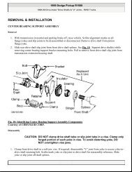
Your <strong>Power</strong> Gear slide-out system is equipped with a manual override that allows you to extend or<br />
retract the room in the event of a loss of power. NOTE: If the room does not move when the<br />
switch is pressed, check the following:<br />
• Battery is fully charged and connected<br />
• The transit bars are removed<br />
• All system fuses/circuit breakers and relays are good.<br />
• Locate the slide-out motor (see drawings later<br />
in this manual). The motor is located in the top<br />
of the center storage compartment under the<br />
slide-out room. For a bedroom slide-out the<br />
motor will be mounted to rail assembly.<br />
• Rotate the brake lever on the back of the<br />
motor counter-clockwise (looking from the<br />
rubber boot end of the motor) about 1/8 of a<br />
turn to the released position. Refer to the label<br />
on the motor and the motor drawing in this<br />
manual. This will release the brake that holds<br />
the room in place. The room is now free to<br />
move.<br />
• Locate the manual override on the end of a rail<br />
assembly (or on the motor itself). It is also<br />
permissible to use an adjustable wrench on<br />
the square drive shaft to crank the room in or<br />
out (if the room is so equipped).<br />
• Check the slide-out awning (some awnings<br />
must be manually unlocked be<strong>for</strong>e operating).<br />
• Using a ¾ wrench or ratchet, crank the room<br />
either in or out completely (depending on your<br />
need).<br />
• When the room is fully in/out apply pressure to<br />
the wrench or ratchet and return the motor<br />
brake lever to the "Engaged" position. This will<br />
ensure the room is locked into a sealed<br />
position.<br />
• Check the slide-out awning (some awnings<br />
must be manually locked be<strong>for</strong>e traveling).<br />
• Install transit bars (if so equipped) and take<br />
the unit to an authorized dealer <strong>for</strong> service.<br />
<strong>Manual</strong>ly Overriding your Slide-out<br />
!!WARNING!!<br />
WHEN THE MOTOR BRAKE IS DISENGAGED THE SLIDE-OUT ROOM WILL NOT LOCK IN<br />
PLACE; THEREFORE, THE ROOM WILL NOT BE SEALED. WHEN THE ROOM HAS BEEN<br />
MANUALLY RETRACTED, BE SURE TO INSTALL THE TRANSIT BARS AND RETURN THE<br />
MOTOR BRAKE LEVER TO ITS NORMAL “ENGAGED” POSITION IN ORDER TO SEAL AND<br />
LOCK THE ROOM INTO POSITION.<br />
4<br />
3010000065 Rev. 0A
ABOVE FLOOR SLIDES WITH ALUMINUM<br />
BASES<br />
5<br />
3010000065 Rev. 0A
ABOVE FLOOR SLIDES WITH STEEL<br />
BASES-DRIVE SIDE<br />
3010000065 Rev. 0A<br />
6
ABOVE FLOOR SLIDES WITH STEEL<br />
BASES-IDLER SIDE<br />
3010000065 Rev. 0A<br />
7
CAGE STYLE SLIDES – BED /<br />
WARDROBE<br />
8<br />
3010000065 Rev. 0A
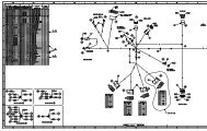
TYPICAL WIRING WITH A RELAY STYLE CONTROLLER<br />
Diagnosing the relay control:<br />
1) Measure voltage between B+ and B-. Voltage less than 11.5 volts<br />
is insufficient. Repair or recharge battery or repair wiring be<strong>for</strong>e<br />
attempting other repairs.<br />
2) Measure voltage at green wire when switch is moved to the “IN”<br />
position. It should be at least 11.5 volts. Voltage less than specified<br />
indicates a bad switch or wires to the switch. Check seat switch<br />
and park brake switches also.<br />
3) Measure voltage at blue wire when switch is moved to the “OUT”<br />
position. It should be at least 11.5 volts. Voltage less than<br />
specified indicates a bad switch or wires to the switch. Check the<br />
seat switch and park brake switches also.<br />
4) Measure voltage between M1 and M2 when switch is moved to the<br />
“IN” position. It should be at least 11 volts. Less than 11 volts<br />
indicates a bad control if all other steps have been OK.<br />
5) Measure voltage between M1 and M2 when switch is moved to the<br />
“OUT” position. It should be at least 11 volts. Less than 11 volts<br />
indicates a bad control if all other steps have been OK.<br />
DN13819<br />
Relay Control<br />
Green Wire<br />
9<br />
**Must be fused per<br />
latest edition of<br />
ANSI/RVIA standard<br />
<strong>for</strong> low voltage<br />
systems in<br />
conversion and<br />
recreational vehicles.<br />
Blue Wire<br />
Red Wire<br />
3010000065 Rev. 0A
FLAT FLOOR ROOM HEIGHT ADJUSTMENT---FLUSH FLOOR STYLE SLIDES<br />
This TIP sheet is designed to provide in<strong>for</strong>mation on setting the room height on a flat floor slide-out<br />
system utilizing angled rails.<br />
With the room fully extended-<br />
• Measure from the top of the moving slide-out rail to the bottom of the slide-out room floor up close to the coach.<br />
This is dimension “A”.<br />
• Measure from the top of the moving slide-out rail to the bottom of the slide-out room floor out near the mounting<br />
bracket. This is dimension “B”.<br />
• To calculate dimension “B” use the following <strong>for</strong>mula:<br />
“B” (end bracket height setting)=“A” + (slideout room floor thickness) + ¼”.<br />
EXAMPLE:<br />
“B” (end bracket height setting) =“A” + (slideout room floor thickness) + ¼”.<br />
If “A” = 3-1/4” AND THE SLIDEOUT FLOOR IS 1” THICK<br />
Then “B”=3-1/4” + 1” + ¼” = 4-1/2”<br />
• Per<strong>for</strong>m this check on each slide-out rail independent of the other.<br />
NOTE:<br />
1) These figures are approximates. Each coach may be slightly different.<br />
2) Refer to manufacturer of coach/trailer <strong>for</strong> correct slideout room floor thickness.<br />
10<br />
3010000065 Rev. 0A
11<br />
SYNCHRONIZING RAILS<br />
3010000065 Rev. 0A
NON-FLUSH FLOOR TYPE ROOM<br />
12<br />
3010000065 Rev. 0A
TROUBLE SHOOTING DC-ELECTRIC MOTORS<br />
13<br />
3010000065 Rev. 0A
<strong>Power</strong> Gear warrants to the original retail purchaser that the product will be free from defects in material and<br />
workmanship <strong>for</strong> a period of (2) years following the retail sales date. Labor to repair these components will<br />
be covered <strong>for</strong> two years. <strong>Power</strong> Gear will, at its option, repair or replace any part covered by this limited<br />
warranty which, following examination by <strong>Power</strong> Gear or its authorized distributors or dealers, is found to be<br />
defective under normal use and service. No claims under this warranty will be valid unless <strong>Power</strong> Gear or its<br />
authorized distributor or dealer is notified in writing of such claim prior to the expiration of the warranty period.<br />
THIS WARRANTY SHALL NOT APPLY TO:<br />
• Failure due to normal wear and tear, accident, misuse, abuse, or negligence.<br />
• Products which are modified or altered in a manner not authorized by <strong>Power</strong> Gear in writing.<br />
• Failure due to misapplication of product.<br />
• Telephone or other communication expenses.<br />
• Living or travel expenses.<br />
• Overtime labor.<br />
• Failures created by improper installation of the product’s slideout system or slideout room to include final adjustments<br />
made at the plant <strong>for</strong> proper room extension/retraction; sealing interface between slideout rooms and side walls;<br />
synchronization of inner rails; or improper wiring or ground problems.<br />
• Failures created by improper installation of leveling systems, including final adjustments made at the plant, or low<br />
fluid level, wiring or ground problems.<br />
• Replacement of normal maintenance items.<br />
There is no other express warranty other than the <strong>for</strong>egoing warranty. THERE ARE NO IMPLIED WARRANTIES OF<br />
MERCHANTIBILITY OR FITNESS FOR A PARTICULAR PURPOSE. IN NO EVENT SHALL POWER GEAR BE<br />
LIABLE FOR ANY INCIDENTAL OR CONSEQUENTIAL DAMAGES. This warranty gives you specific legal rights, and<br />
you may also have other rights, which vary from state to state. Some states do not allow the limitations of implied<br />
warranties, or the exclusion of incidental or consequential damages, so the above limitations and exclusions may not<br />
apply to you.<br />
For service contact your nearest <strong>Power</strong> Gear authorized warranty service facility or call 1-800-334-4712. Warranty<br />
service can be per<strong>for</strong>med only by a <strong>Power</strong> Gear authorized service facility. This warranty will not apply to service at<br />
any other facility. At the time of requesting warranty service, evidence of original purchase date must be presented.<br />
<strong>Power</strong> Gear<br />
1217 E. 7 th Street<br />
Mishawaka, IN 46544<br />
800/334-4712<br />
www.powergearus.com<br />
14<br />
<strong>Power</strong> Gear Warranty Policy<br />
3010000065 Rev. 0A