Create successful ePaper yourself
Turn your PDF publications into a flip-book with our unique Google optimized e-Paper software.
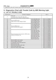
AR05.20-S-6992C <strong>Remove</strong>/<strong>install</strong> <strong>camshafts</strong> 30.1.09<br />
ENGINE 611.980 in MODEL 638.094 /194 /294<br />
with CODE (MQ4) Engine OM611 DE22 LA (75 kW)<br />
with CODE (MQ5) Engine OM611 DE22 LA (90 kW)<br />
ENGINE 611.980 in MODEL 638.094 /194 with CODE (MQ3) Engine OM611 DE22 A (60 kW)<br />
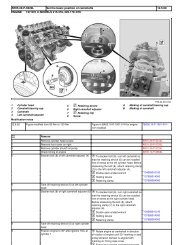
1 Exhaust camshaft 6 Exhaust camshaft sprocket 11 Sealing ring<br />
2 Intake camshaft 7 Dowel pin 12 Bolt<br />
3 Retaining pin 8 Camshaft bearing cap A Bore<br />
4 Cylinder head cover 9 Bolt B Bore<br />
5 Inlet camshaft sprocket 10 Chain tensioner<br />
Removing<br />
S05.20-2504-09<br />
Danger! Risk of explosion caused by ignition of No fire, sparks, open flames or smoking. AS47.00-Z-0001-01A<br />
flammable products, risk of poisoning Only pour fuels into suitable and<br />
caused by inhaling fuel vapors or swallowing appropriately marked containers.<br />
fuel as well as risk of injury to skin and Wear protective clothing when handling fuel.<br />
eyes exposed to fuel.<br />
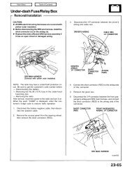
1 <strong>Remove</strong> injectors AR07.16-S-1000A<br />
*602589003300<br />
*611589013300<br />
*611589006800<br />
*000589266800<br />
*001589760900<br />
Notes on injectors AH07.16-P-1000-01A<br />
Clean injector stems and injectors with a<br />
wire brush. Grease injector stems with<br />
special grease. Clean injector recesses with a<br />
round brush and cylinder brush, blow out<br />
and cover over. Seal injector recesses with<br />
pin before cleaning.<br />
Replace injector seal and screws of<br />
tensioning clamps.<br />
Special grease *BR00.45-Z-1036-06A<br />
2 <strong>Remove</strong> cylinder head cover (4) AR01.20-S-5014D<br />
3 Position piston of cylinder 1 to ignition TDC AR01.00-S-0120D<br />
Crank engine at crankshaft.<br />
4 Install retaining lock for crankshaft/starter AR03.30-S-5000C<br />
ring gear<br />
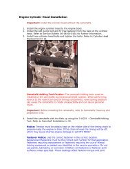
5 Lock intake camshaft (2) Insert retaining pin (3) through the 1st<br />
camshaft bearing cap into the hole (A) of<br />
the intake camshaft gear (5).<br />
*111589031500<br />
6 <strong>Remove</strong> chain tensioner (10) AR05.10-S-7800D<br />
7 <strong>Remove</strong> front cover at cylinder head AR01.30-S-5700A<br />
© Daimler AG, 11/19/09, G/11/09 / ar05.20-s-6992c / <strong>Remove</strong>/<strong>install</strong> <strong>camshafts</strong><br />
Page 1/4<br />
ENGINE 611.980 in MODEL 638.094 /194 /294 with CODE (MQ4) Engine OM611 DE22 LA (75 kW) with CODE (MQ5) Engine OM611 DE22 LA (90 kW) ENGINE 611.980 in MODEL 638.094 ...
8 <strong>Remove</strong> top slide rail AR05.10-S-8432C<br />
9 Mark intake camshaft sprocket (5) relative to For all work in which the crankshaft<br />
timing chain should not be rotated, connect the intake<br />
camshaft sprocket (5) and timing chain by<br />
using cable ties.<br />
10 Unbolt exhaust camshaft sprocket (6) from *BA05.10-P-1003-01A<br />
exhaust camshaft (1)<br />
11 Take off exhaust camshaft sprocket (6) Pay attention to dowel pin (7) (arrow).<br />
Take off exhaust camshaft sprocket (6) with<br />
timing chain fitted on.<br />
12 Unbolt camshaft bearing cap (8) AR05.20-P-6992-05A<br />
13 <strong>Remove</strong> intake camshaft (2) and exhaust<br />
camshaft (1)<br />
Install<br />
Pay attention to marking of camshaft<br />
bearing cap (8)!<br />
14 Insert intake camshaft (2) and exhaust The <strong>camshafts</strong> (1, 2) are sensitive to<br />
camshaft (1) fracturing. Ensure they are <strong>install</strong>ed free of<br />
stress.<br />
Installation: Oil cup tappets and<br />
camshaft bearing points, inspect ease of<br />
operation of cup tappets. Align inlet and<br />
exhaust <strong>camshafts</strong> (1, 2) at the thrust<br />
bearing (arrows).<br />
Install <strong>camshafts</strong> (1, 2) so that the two<br />
holes (B) in the camshaft sprockets (5, 6)<br />
are positioned opposite and the markings of<br />
camshaft (1, 2) (arrows) and camshaft<br />
bearing cap (8) are aligned. The <strong>camshafts</strong><br />
(1, 2) are very sensitive to fracturing. Ensure<br />
they are <strong>install</strong>ed free of stress.<br />
Pay attention to assignment of<br />
<strong>camshafts</strong>!<br />
The camshaft code numbers are visible in<br />
each case on the thrust collar of the axial<br />
bearing.<br />
Timing<br />
Timing<br />
AH05.20-P-6992-04HB<br />
*BE05.20-N-1001-01C<br />
*BE05.20-P-1001-02A<br />
*BE05.20-P-1002-02A<br />
15 <strong>Remove</strong> retaining lock AR03.30-S-5000C<br />
16 Position piston of cylinder 1 to 30° BTDC Rotate engine at crankshaft. Do not<br />
rotate engine at the bolt of the camshaft<br />
sprocket (5, 6). Do not rotate engine<br />
backwards.<br />
AR01.00-S-0120D<br />
17 Install camshaft bearing cap (8)<br />
Markings on camshaft/camshaft bearing<br />
cap (8) (arrows) must be aligned.<br />
Install camshaft bearing caps (8) in the<br />
reverse order at the same point. Tighten<br />
bolts (12) evenly in steps each of 1 turn.<br />
AR05.20-P-6992-05A<br />
Pay attention to marking of camshaft<br />
bearing cap (8).<br />
AH05.20-P-6992-04HB<br />
*BA05.20-P-1001-01F<br />
18 Position piston of cylinder 1 to ignition TDC AR01.00-S-0120D<br />
19 Lock intake camshaft (2) Insert retaining pin (3) through the 1st<br />
camshaft bearing cap (8) into the hole (A) of<br />
the intake camshaft gear (5).<br />
The piston of cylinder 1 must be<br />
positioned at ignition TDC when the intake<br />
camshaft (2) is locked.<br />
*111589031500<br />
20 Fit exhaust camshaft sprocket (6) onto<br />
exhaust camshaft (1)<br />
Installation: Replace bolts (9) of<br />
exhaust camshaft sprocket (6).<br />
Pay attention to dowel pin (7) (arrow).<br />
Fit on exhaust camshaft sprocket (6) with<br />
timing chain fitted on.<br />
*BA05.10-P-1003-01A<br />
21 Install chain tensioner (10) AR05.10-S-7800D<br />
Replace compression ring (11).<br />
22 Check basic position of the <strong>camshafts</strong> (1, 2) AR05.20-S-6010C<br />
If necessary, after inspecting<br />
Set basic position of the <strong>camshafts</strong> (1, 2) AR05.20-S-6020B<br />
23 Install cylinder head cover (4) AR01.20-S-5014D<br />
24 Install injectors AR07.16-S-1000A<br />
Checking<br />
© Daimler AG, 11/19/09, G/11/09 / ar05.20-s-6992c / <strong>Remove</strong>/<strong>install</strong> <strong>camshafts</strong><br />
Page 2/4<br />
ENGINE 611.980 in MODEL 638.094 /194 /294 with CODE (MQ4) Engine OM611 DE22 LA (75 kW) with CODE (MQ5) Engine OM611 DE22 LA (90 kW) ENGINE 611.980 in MODEL 638.094 ...
Danger! Risk of accident caused by vehicle starting Secure vehicle to prevent it from moving by AS00.00-Z-0005-01A<br />
off by itself when engine is running. Risk of itself.<br />
injury caused by contusions and burns Wear closed and snug-fitting work clothes.<br />
during starting procedure or when working Do not touch hot or rotating parts.<br />
near the engine as it is running<br />
25 Check for oil leaks with engine running<br />
Danger!<br />
Risk of explosion from fuel igniting. Risk<br />
of injury to skin and eyes caused by fuel<br />
Keep all ignition sources out of hazard area.<br />
Do not carry out any work on system when<br />
AS07.16-Z-0001-01A<br />
spraying out at high pressure. it is pressurized.<br />
26 Check fuel system for leaks with engine<br />
running<br />
27 Read out fault memory and erase Stored faults possibly caused by previous AD00.00-P-2000-03A<br />
simulation or by cables disconnected in the<br />
process of <strong>install</strong>ation or testing must be<br />
processed and erased in the DTC memories<br />
once all work is completed. Refer to:<br />
Diagnosis manual for diesel engine, Volume<br />
1.2<br />
Timing<br />
Number Designation Engine<br />
611.980<br />
BE05.20-P-1001-02A<br />
BE05.20-P-1002-02A<br />
Camshaft code numbers<br />
Timing inlet valve/ Intake valve opens after TDC °CA 19<br />
exhaust valve at 2 mm valve lift and<br />
used timing chain<br />
closes after BDC °CA 7<br />
Timing inlet valve/ Exhaust opens before °CA 9<br />
exhaust valve at 2 mm valve lift and<br />
used timing chain<br />
valve BDC<br />
Number Designation Engine<br />
611.980<br />
BE05.20-N-1001-01C Camshaft code numbers Inlet 01<br />
Timing chain, chain tensioner<br />
Outlet 00<br />
closes before °CA 22<br />
TDC<br />
Number Designation Engine<br />
BA05.10-P-1003-01A Bolt, camshaft sprocket to exhaust camshaft Nm 18<br />
Camshaft<br />
611.980<br />
© Daimler AG, 11/19/09, G/11/09 / ar05.20-s-6992c / <strong>Remove</strong>/<strong>install</strong> <strong>camshafts</strong><br />
Page 3/4<br />
ENGINE 611.980 in MODEL 638.094 /194 /294 with CODE (MQ4) Engine OM611 DE22 LA (75 kW) with CODE (MQ5) Engine OM611 DE22 LA (90 kW) ENGINE 611.980 in MODEL 638.094 ...
Number Designation Engine<br />
611.960/961/962/980/<br />
BA05.20-P-1001-01F Bolt, camshaft bearing cap to cylinder head Nm 9<br />
981/983/987<br />
612.961/962/963/965/<br />
966/967/981/990<br />
613.960/961<br />
111 589 03 15 00 602 589 00 33 00 611 589 01 33 00 611 589 00 68 00<br />
Retaining pins Impact extractor Extraction claw Round brush<br />
000 589 26 68 00 001 589 76 09 00<br />
Repair materials<br />
Brake caliper brush External Torx set<br />
Number Designation Order number<br />
BR00.45-Z-1036-06A Special grease A 001 989 42 51 10<br />
© Daimler AG, 11/19/09, G/11/09 / ar05.20-s-6992c / <strong>Remove</strong>/<strong>install</strong> <strong>camshafts</strong><br />
Page 4/4<br />
ENGINE 611.980 in MODEL 638.094 /194 /294 with CODE (MQ4) Engine OM611 DE22 LA (75 kW) with CODE (MQ5) Engine OM611 DE22 LA (90 kW) ENGINE 611.980 in MODEL 638.094 ...