Manual Motor Control Switches and Disconnects - Schneider Electric
Manual Motor Control Switches and Disconnects - Schneider Electric
Manual Motor Control Switches and Disconnects - Schneider Electric

You also want an ePaper? Increase the reach of your titles
YUMPU automatically turns print PDFs into web optimized ePapers that Google loves.
Catalog<br />
03<br />
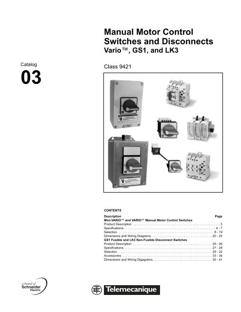
<strong>Manual</strong> <strong>Motor</strong> <strong>Control</strong><br />
<strong>Switches</strong> <strong>and</strong> <strong>Disconnects</strong><br />
Vario, GS1, <strong>and</strong> LK3<br />
Class 9421<br />
CONTENTS<br />
Description Page<br />
Mini-VARIO <strong>and</strong> VARIO <strong>Manual</strong> <strong>Motor</strong> <strong>Control</strong> <strong>Switches</strong><br />
Product Description . . . . . . . . . . . . . . . . . . . . . . . . . . . . . . . . . . . . . . . . . . . . . . . . . . 3<br />
Specifications . . . . . . . . . . . . . . . . . . . . . . . . . . . . . . . . . . . . . . . . . . . . . . . . . . . . 4 - 7<br />
Selection . . . . . . . . . . . . . . . . . . . . . . . . . . . . . . . . . . . . . . . . . . . . . . . . . . . . . . 8 - 19<br />
Dimensions <strong>and</strong> Wiring Diagrams. . . . . . . . . . . . . . . . . . . . . . . . . . . . . . . . . . . 20 - 25<br />
GS1 Fusible <strong>and</strong> LK3 Non-Fusible Disconnect <strong>Switches</strong><br />
Product Description . . . . . . . . . . . . . . . . . . . . . . . . . . . . . . . . . . . . . . . . . . . . . 25 - 26<br />
Specifications . . . . . . . . . . . . . . . . . . . . . . . . . . . . . . . . . . . . . . . . . . . . . . . . . . 27 - 28<br />
Selection . . . . . . . . . . . . . . . . . . . . . . . . . . . . . . . . . . . . . . . . . . . . . . . . . . . . . . 29 - 32<br />
Accessories . . . . . . . . . . . . . . . . . . . . . . . . . . . . . . . . . . . . . . . . . . . . . . . . . . . 33 - 34<br />
Dimensions <strong>and</strong> Wiring Digagrams. . . . . . . . . . . . . . . . . . . . . . . . . . . . . . . . . . 35 - 41
Product Description<br />
Mini-VARIO <strong>and</strong> VARIO <strong>Manual</strong> <strong>Motor</strong> <strong>Control</strong> <strong>Switches</strong><br />
Product Descriptions<br />
Applications Mini-Vario <strong>and</strong> Vario rotary manual motor control switches from 12 to 175 A are suitable for on-load making <strong>and</strong> breaking of resistive<br />
or mixed resistive <strong>and</strong> inductive circuits where frequent operation is required. They can also be used for direct switching of motors in<br />
utilization categories AC-3 <strong>and</strong> DC-3 specific to motors.Vario manual motor control switches are suitable for isolator applications with<br />
fully visible indication (since the h<strong>and</strong>le cannot be in the open position unless all the contacts are actually open <strong>and</strong> separated by the<br />
appropriate isolating distance) <strong>and</strong> it is possible to padlock the h<strong>and</strong>les.<br />
Switch Type<br />
★ Enclosures not UL listed<br />
International Acceptance<br />
UL Listed, CSA Certified, IEC Rated, CE Marked, <strong>and</strong> most other applicable international st<strong>and</strong>ards.<br />
UL508, CSA 22.2 No. 14 - UL File # E164864 CCN NLRV, CSA File # LR81630 Class 3211 05.<br />
Suitable for use in equipment or machinery as manual motor controllers <strong>and</strong> are horsepower <strong>and</strong> ampere rated.<br />
IEC<br />
Tested in accordance to IEC 60947-3, IEC 60529, <strong>and</strong> IEC 60695-2-1.<br />
CE<br />
Mini-VARIO for St<strong>and</strong>ard<br />
Applications<br />
Compliance with the European Machine Directive IEC 60204.<br />
VARIO for High Performance Applications<br />
Thermal Current, UL/IEC 10 A/12 A 16 A/20 A 10 A/12 A 16 A/20 A 20 A/25 A 20 A/32 A 25 A/40 A 45 A/63 A 63 A/80 A 100 A/125 A 110 A/175 A<br />
Operational Current<br />
AC-23 A at 400 Volts<br />
8.1 A 11 A 8.1 A 11 A 14.5 A 21.6 A 29 A 41.5 A 57 A 68.5 A 83 A<br />
Number of Poles 3 to 5 3 to 5 3 to 6 3 to 6 3 to 6 3 to 6 3 to 6 3 to 6 3 to 6 3 + N + PE 3 + N + PE<br />
Number of<br />
Auxiliary Contacts<br />
Switch Mounting<br />
from the Front<br />
1 or 2 1 or 2 1 to 4 1 to 4 1 to 4 1 to 4 1 to 4 1 to 4 1 to 4 1 to 4 1 to 4<br />
Screw mounting 1 or 4 holes<br />
1 x ∅ 0.88 in (1 x ∅ 22.5 mm) hole or<br />
1 x ∅ 0.2 in (4 x ∅ 5.5 mm) screws<br />
Screw mounting 1 or 4 holes<br />
1 x ∅ 0.88 in (1 x ∅ 22.5 mm) hole or<br />
1 x ∅ 0.2 in( (4 x ∅ 5.5 mm) screws<br />
1 x ∅ 0.2 in (4 x ∅ 5.5 mm) screw<br />
from the Back Clip-on Mounting on DIN Rail Clip-on Mounting on DIN Rail or Screw Screw<br />
Reversible<br />
Terminal Blocks<br />
Yes Yes Yes Yes Yes Yes Yes Yes Yes Yes Yes<br />
Door Mounting Yes Yes Yes Yes Yes Yes Yes Yes Yes Yes Yes<br />
Mounting at Back<br />
of Enclosure with<br />
Door Interlock<br />
Enclosure Catalog ★<br />
Number<br />
®<br />
Yes Yes Yes Yes Yes Yes Yes Yes Yes Yes Yes<br />
VDN12 VDN20<br />
VD02<br />
VF02<br />
VD01<br />
VF01<br />
03/04 © 1999-2004 <strong>Schneider</strong> <strong>Electric</strong> All Rights Reserved<br />
VD0<br />
VF0<br />
VD1<br />
VF1<br />
VD2<br />
VF2<br />
VF3 VF4 VF5 VF6<br />
Listed Certified Marked<br />
3
Mini-VARIO <strong>and</strong> VARIO <strong>Manual</strong> <strong>Motor</strong> <strong>Control</strong> <strong>Switches</strong><br />
Specifications<br />
Specifications<br />
4<br />
Switch Type<br />
© 1999-2004 <strong>Schneider</strong> <strong>Electric</strong> All Rights Reserved<br />
VN12<br />
VZN12<br />
V02<br />
VZ02<br />
VN20<br />
VZN20<br />
Environment<br />
Conforming to St<strong>and</strong>ards IEC 60947-3<br />
Approvals UL, CSA, GL, UL File # E164864 CCN NLRV, CSA File # LR81630 Class 3211 05<br />
Protective Treatment “TC”<br />
Degree of Protection<br />
with Protection Shroud<br />
IP 20 conforming to IEC 60529<br />
Ambient Air Temperature -4 to +122 °F (-20 to +50 °C)<br />
Flame Resistance 1760 °F (960 °C) conforming to IEC 60695-2-1<br />
Shock Resistance<br />
1/2 Sine Wave = 11ms<br />
Conforming to IEC 60068-2-27<br />
Vibration Resistance<br />
10 to 150 Hz<br />
Conforming to IEC 60068-2-6<br />
V01<br />
VZ01<br />
V0<br />
VZ0<br />
VVD0<br />
VVE0<br />
15 g 30 g 15 g 30 g<br />
5 g 1 g 1 g 1 g<br />
<strong>Electric</strong>al Characteristics, AC Operation<br />
Rated Operational Voltage (Ue) V 690 690 690 690 690 690 690 690<br />
Rated Impulse Withst<strong>and</strong> Voltage (Uimp) kV 6 8 6 8 8 8 8 8<br />
Conventional Thermal Currents in Free Air<br />
(Ith) <strong>and</strong> Rated Uninterrupted (Iu)<br />
A 12 20 25 32<br />
Conventional Thermal Current in Enclosure<br />
(Ithe)<br />
A 10 16 20 25<br />
Rated Operational Power <strong>and</strong> Current<br />
AC-21A/22A 230 to 690 V A 12 20 25 32<br />
AC-23A 230 V A (kW) 10.6 (3) 14 (4) 19.7 (5.5) 19.7 (5.5)<br />
240 V A (kW) 10.6 (3) 14 (4) 19.9 (5.5) 18.9 (5.5)<br />
400 V A (kW) 8.1 (4) 11 (5.5) 14.5 (7.5) 21.8 (11)<br />
415 V A (kW) 8.1 (4) 11 (5.5) 14 (7.5) 21 (11)<br />
500 V A (kW) 8.9 (5.5) 11.9 (7.5) 16.7 (11) 16.7 (11)<br />
690 V A (kW) 8.6 (7.5) 12.3 (11) 17.5 (15) 17.5 (15)<br />
Rated Operational Power<br />
AC-3 230/240 V Hp (kW) 2 (1.5) 2 (1.5) 4 (3) 4 (3) 5 (4) 5 (4)<br />
400/415 V Hp (kW) 4 (3) 4 (3) 5 (4) 5 (4) 7 (5.5) 10 (7.5)<br />
500 V Hp (kW) 5 (4) 5 (4) 7 (5.5) 7 (5.5) 10 (7.5) 10 (7.5)<br />
690 V Hp (kW) 5 (4) 7 (5.5) 7 (5.5) 10 (7.5) 15 (11) 15 (11)<br />
Intermittent Duty Class<br />
Characteristics in Normal<br />
Operating Conditions<br />
30 30 30 30<br />
Rated Making Capacity<br />
AC-21A/22A/23A (I rms)<br />
A/400 V 120 200 250 320<br />
Rated Breaking Capacity<br />
AC-21A/22A/23A (I rms)<br />
Short-circuit Characteristics<br />
Permissible ms Short Time<br />
Rating (Icw)<br />
Rated Making Capacity Under<br />
Short-circuit Condition (Icm) I Peak<br />
Rated Conditional Short-circuit<br />
Current (I rms)<br />
A/400 V 120 200 200 250<br />
A/400V/1s 140 300 140 300 300 384<br />
kA/400 V 0.5 1 0.5 1 1 1<br />
kA/400 V 6 10 6 10 10 10<br />
with a M/g G Fuses A 12 20 25 35<br />
V1<br />
VZ1<br />
VVD1<br />
VVE1<br />
03/04
Switch Type<br />
Mini-VARIO <strong>and</strong> VARIO <strong>Manual</strong> <strong>Motor</strong> <strong>Control</strong> <strong>Switches</strong><br />
Specifications<br />
V2<br />
V2<br />
VVD2<br />
VVE2<br />
03/04 © 1999-2004 <strong>Schneider</strong> <strong>Electric</strong> All Rights Reserved<br />
V3<br />
VZ3<br />
VVD3<br />
VVE3<br />
V4<br />
VZ4<br />
VVD4<br />
VVE4<br />
V5 V6<br />
Environment<br />
Conforming to St<strong>and</strong>ards IEC 947-3 947-5<br />
Approvals UL, CSA, GL, UL File # E164864 CCN NLRV, CSA File # LR81630 Class 3211 05<br />
Protective Treatment “TC”<br />
Degree of Protection<br />
with Protection Shroud<br />
IP 20 conforming to IEC 529<br />
Ambient Air Temperature -4 to +122 °F (-20 to +50 °C)<br />
Flame Resistance 960 °C (1760 °F) conforming to IEC 695-2-1<br />
Shock Resistance<br />
1/2 Sine Wave = 11ms<br />
Conforming to IEC 60068-2-27<br />
Vibration Resistance<br />
10 to 150 Hz<br />
Conforming to IEC 60068-2-6<br />
VZ7<br />
VZ20<br />
30 g –<br />
1 g –<br />
<strong>Electric</strong>al Characteristics, AC Operation<br />
Rated Operational Voltage (Ue) V 690 690 690 690 690 690 690<br />
Rated Impulse Withst<strong>and</strong> Voltage (Uimp) kV 8 8 8 8 8 8 6<br />
Conventional Thermal Currents in Free Air<br />
(Ith) <strong>and</strong> Rated Uninterrupted (Iu)<br />
A 40 63 80 125 175 12 6<br />
Conventional Thermal Current in Enclosure<br />
(Ithe)<br />
A 32 50 63 100 140 10 4<br />
Rated Operational Power <strong>and</strong> Current<br />
AC-21A/22A 230 to 690 V A 40 63 80 125 160 Ie/AC-15 Ie/AC-15<br />
AC-23A 230 V A (kW) 25.8 (7.5) 50.3 (15) 61.2 (18.5) 71.9 (22) 96.6 (30) 6 A 6 A<br />
240 V A (kW) 24.8 (7.5) 48.2 (15) 58.5 (18.5) 68 (22) 92.7 (30) 6 A 6 A<br />
400 V A (kW) 29 (15) 41.5 (22) 57 (30) 68.5 (37) 83 (45) 4 A 4 A<br />
415 V A (kW) 28 (15) 40 (22) 55 (30) 66 (37) 80 (45) 4 A 4 A<br />
500 V A (kW) 28.5 (18.5) 44 (30) 54 (37) 64.5 (45) 79 (55) 2 A 2 A<br />
690 V A (kW) 17.5 (15) 25 (22) 33 (30) 42 (37) 49 (45) 1 A 1 A<br />
Rated Operational Power<br />
AC-3 230/240 V Hp (kW) 7 (5.5) 14.75 (11) 20 (15) 30 (22) 40 (30) – –<br />
400/415 V Hp (kW) 14.75 (11) 24 (18.5) 30 (22) 40 (30) 50 (37) – –<br />
500 V Hp (kW) 20 (15) 30 (22) 40 (30) 50 (37) 60 (45) – –<br />
690 V Hp (kW) 14.75 (11) 24 (18.5) 24 (18.5) 40 (30) 50 (37) – –<br />
Intermittent Duty Class<br />
Characteristics in Normal<br />
Operating Conditions<br />
30 30 30 30 30 – –<br />
Rated Making Capacity<br />
AC-21A/22A/23A (I rms)<br />
A/400 V 400 630 800 1250 1750 – –<br />
Rated Breaking Capacity<br />
AC-21A/22A/23A (I rms)<br />
Short-circuit Characteristics<br />
Permissible ms Short Time<br />
Rating (Icw)<br />
Rated Making Capacity Under<br />
Short-circuit Condition (Icm) I Peak<br />
Rated Conditional Short-circuit<br />
Current (I rms)<br />
A/400 V 320 500 640 1000 1400 – –<br />
A/400 V/1s 480 756 960 1500 2100 – –<br />
kA/400 V 1 2.1 2.1 2.8 2.8 – –<br />
kA/400 V 10 10 10 10 10 1 1<br />
with a M/g G Fuses A 50 63 80 125 200 16 1.6<br />
VZN05<br />
VZN06<br />
5
Mini-VARIO <strong>and</strong> VARIO <strong>Manual</strong> <strong>Motor</strong> <strong>Control</strong> <strong>Switches</strong><br />
Specifications<br />
6<br />
Switch Type<br />
© 1999-2004 <strong>Schneider</strong> <strong>Electric</strong> All Rights Reserved<br />
VN12<br />
VZN12<br />
<strong>Electric</strong>al Characteristics, DC Operation<br />
Rated Operational Current (contacts in series)<br />
DC-1 (L/R = 1 ms) 24 V 1 contact A 12 20 25 32<br />
2 contacts A 12 20 25 32<br />
3 contacts A 12 20 25 32<br />
48 V 1 contact A 12 20 25 32<br />
2 contacts A 12 20 25 32<br />
3 contacts A 12 20 25 32<br />
60V 1 contact A 12 20 25 32<br />
2 contacts A 12 20 25 32<br />
3 contacts A 12 20 25 32<br />
110 V 1 contact A 1.5 2 9 10<br />
2 contacts A 8 10 12 16<br />
3 contacts A 12 20 25 32<br />
220 V 1 contact A 1.5 2 2.5 3<br />
2 contacts A 7 8 10 12<br />
3 contacts A 10 14 16 20<br />
250V 1 contact A 0.6 0.7 0.8 1<br />
2 contacts A 3 4 6 8<br />
3 contacts A 8 10 12 16<br />
Rated Operational Current (contacts in series)<br />
DC-2 TO DC-5 24 V 1 contact A 12 20 25 32<br />
(L/R = 1ms) 2 contacts A 12 20 25 32<br />
3 contacts A 12 20 25 32<br />
48 V 1 contact A 12 20 25 32<br />
2 contacts A 12 20 25 32<br />
3 contacts A 12 20 25 32<br />
60 V 1 contact A 10 14 16 20<br />
2 contacts A 12 20 25 32<br />
3 contacts A 12 20 25 32<br />
110 V 1 contact A 1.5 2 2.5 3<br />
2 contacts A 3 4 5 6<br />
3 contacts A 12 20 25 32<br />
220 V 1 contact A 0.4 0.5 0.5 0.8<br />
2 contacts A 1.4 1.5 1.5 2<br />
3 contacts A 1 2 3 4<br />
250 V 1 contact A 0.3 0.4 0.5 0.8<br />
2 contacts A 0.4 0.6 0.8 1<br />
Other Characteristics<br />
3 contacts A 1.2 2.4 1.6 2<br />
Mechanical Durability<br />
Millions of Op.<br />
Cycles<br />
0.05 0.1 0.05 0.1 0.1 0.1<br />
<strong>Electric</strong>al Durability in Cat. AC-21<br />
<strong>Electric</strong>al Durability in Cat. DC-1 to 5<br />
Millions of Op.<br />
Cycles<br />
Operating<br />
Cycles<br />
V02<br />
VZ02<br />
VN20<br />
VZN20<br />
V01<br />
VZ01<br />
V0<br />
VZ0<br />
VVD0<br />
VVE0<br />
V1<br />
VZ1<br />
0.05 0.1 0.05 0.1 0.1 0.1<br />
30,000 30,000 30,000 30,000<br />
Suitable for Isolation Yes Yes Yes Yes<br />
Cabling<br />
Flexible Cable + Cable<br />
End<br />
AWG (mm 2 ) 12 (4) 10 (6) 12 (4) 10 (6) 10 (6) 10 (6)<br />
Solid Cable AWG (mm 2 ) 12 (4) 8 (10) 12 (4) 8 (10) 8 (10) 8 (10)<br />
Tightening Torque lb-in (Nm ) 6.2 (0.7) 18.6 (2.1) 6.2 (0.7) 18.6 (2.1) 18.6 (2.1) 18.6 (2.1)<br />
VVD1<br />
VVE1<br />
03/04
Switch Type<br />
Mini-VARIO <strong>and</strong> VARIO <strong>Manual</strong> <strong>Motor</strong> <strong>Control</strong> <strong>Switches</strong><br />
Specifications<br />
V2<br />
VZ2<br />
03/04 © 1999-2004 <strong>Schneider</strong> <strong>Electric</strong> All Rights Reserved<br />
VDD2<br />
VVE2<br />
V3<br />
VZ3<br />
VVD3<br />
VVE3<br />
V4<br />
VZ4<br />
VVD4<br />
VVE4<br />
V5 V6<br />
<strong>Electric</strong>al Characteristics, DC Operation<br />
Rated Operational Current (contacts in series)<br />
DC-1 (L/R = 1 ms) 24 V 1 contact A 40 63 80 125 175 8 (le/DC-11)<br />
2 contacts A 40 63 80 125 175 –<br />
3 contacts A 40 63 80 125 175 –<br />
48 V 1 contact A 40 63 80 125 175 8 (le/DC-11)<br />
2 contacts A 40 63 80 125 175 –<br />
3 contacts A 40 63 80 125 175 –<br />
60V 1 contact A 35 40 50 60 70 4 (le/DC-11)<br />
2 contacts A 40 63 80 125 175 –<br />
3 contacts A 40 63 80 125 175 –<br />
110 V 1 contact A 12 20 25 30 12 2 (le/DC-11)<br />
2 contacts A 20 63 80 125 175 –<br />
3 contacts A 40 63 80 125 175 –<br />
220 V 1 contact A 4 6 8 12 15 1 (le/DC-11)<br />
2 contacts A 14 25 30 40 50 –<br />
3 contacts A 25 30 40 80 100 –<br />
250V 1 contact A 2 4 5 6 10 0.8 (le/DC-11)<br />
2 contacts A 12 20 25 30 40 –<br />
3 contacts A 20 30 40 50 61 –<br />
Rated Operational Current (contacts in series)<br />
DC-2 TO DC-5 24 V 1 contact A 40 63 80 125 175 –<br />
(L/R = 1ms) 2 contacts A 40 63 80 125 175 –<br />
3 contacts A 40 63 80 125 175 –<br />
48 V 1 contact A 40 63 80 125 175 –<br />
2 contacts A 40 63 80 125 175 –<br />
3 contacts A 40 63 80 125 175 –<br />
60 V 1 contact A 25 40 50 60 70 –<br />
2 contacts A 40 63 80 125 175 –<br />
3 contacts A 40 63 80 125 175 –<br />
110 V 1 contact A 5 6 8 10 12 –<br />
2 contacts A 8 10 20 22 24 –<br />
3 contacts A 40 50 63 70 80 –<br />
220 V 1 contact A 1 1.5 2 2.2 2.4 –<br />
2 contacts A 3 4 6 7 8 –<br />
3 contacts A 7 10 15 16 13 –<br />
250 V 1 contact A 1 1.2 1.5 1.6 1.8 –<br />
2 contacts A 2 3 6 7 8 –<br />
Other Characteristics<br />
3 contacts A 6 8 10 12 14 –<br />
Mechanical Durability<br />
Millions of Op.<br />
Cycles<br />
0.1 0.03 0.03 0.03 0.03 0.1 0.05<br />
<strong>Electric</strong>al Durability in Cat. AC-21<br />
<strong>Electric</strong>al Durability in Cat. DC-1 to 5<br />
Millions of Op.<br />
Cycles<br />
Operating<br />
Cycles<br />
0.1 0.03 0.03 0.03 0.03<br />
VZ7<br />
VZ20<br />
0.1<br />
(AC-15)<br />
VZN5<br />
VZN06<br />
30,000 30,000 30,000 30 K 30 K 30,000 (DC-11)<br />
Suitable for Isolation Yes Yes Yes Yes Yes –<br />
Cabling<br />
Flexible Cable + Cable<br />
End<br />
AWG (mm 2 ) 10 (6) 6 (16) 6 (16) 2/0 (70) 2/0 (70)<br />
Solid Cable AWG (mm 2 ) 8 (10) 4 (25) 4 (25) 3/0 (95) 3/0 (95)<br />
Tightening Torque lb-in (Nm) 18.6 (2.1) 35.4 (4) 35.4 (4)<br />
200<br />
(22.6)<br />
200<br />
(22.6)<br />
0.05<br />
18 to 16<br />
(2 x 0.75 to 1.5)<br />
16 to 14<br />
(2 x 1 to 2.5)<br />
6.2 (0.7)<br />
7
Mini-VARIO <strong>and</strong> VARIO <strong>Manual</strong> <strong>Motor</strong> <strong>Control</strong> <strong>Switches</strong><br />
Selection<br />
8<br />
VCDN20<br />
VCCDN20<br />
VBDN20<br />
VCFNGE<br />
(yellow cover with red h<strong>and</strong>le)<br />
Selection<br />
© 1999-2004 <strong>Schneider</strong> <strong>Electric</strong> All Rights Reserved<br />
— 3-pole rotary manual motor control switches, 10 to 16 A (UL), 12 to 20 A (IEC).<br />
— Marking on operator.<br />
— Padlockable operating h<strong>and</strong>le (padlocks not supplied).<br />
Complete Units<br />
— Degree of protection IP 65, NEMA/UL Type 1 <strong>and</strong> 12.<br />
Main <strong>Manual</strong> <strong>Motor</strong> <strong>Control</strong> Switch for Door Mounting<br />
Red,<br />
padlockable with<br />
up to 3 padlocks<br />
Enclosures<br />
Operator H<strong>and</strong>le<br />
Front Plate<br />
in (mm)<br />
Yellow<br />
2.38 x 2.38<br />
(60 x 60)<br />
— Degree of protection IP 55, non-NEMA.<br />
— Sealable enclosure.<br />
Mounting<br />
in (mm)<br />
∅ 0.88 (22.5)<br />
◆ <strong>Switches</strong> supplied with a shaft extension VZN17 <strong>and</strong> a door interlock plate KZ32 (see page 10).<br />
★ Enclosure not UL listed<br />
Rating (A) Catalog<br />
UL IEC Number<br />
Weight<br />
lbs (kg)<br />
10 12 VCDN12 0.39 (0.177)<br />
16 20 VCDN20 0.39 (0.177)<br />
Main <strong>Manual</strong> <strong>Motor</strong> <strong>Control</strong> <strong>Switches</strong> for Mounting at Back of an Enclosure ◆<br />
Red,<br />
padlockable with<br />
up to 3 padlocks<br />
Operator H<strong>and</strong>le<br />
Front Plate<br />
in (mm)<br />
Yellow<br />
2.38 x 2.38<br />
(60 x 60)<br />
Mounting<br />
in (mm)<br />
∅ 0.88 (22.5)<br />
Main <strong>Manual</strong> <strong>Motor</strong> <strong>Control</strong> <strong>Switches</strong> for Door Mounting<br />
Black,<br />
padlockable with<br />
up to 3 padlocks<br />
Operator H<strong>and</strong>le<br />
Front Plate<br />
in (mm)<br />
Black<br />
2.38 x 2.38<br />
(60 x 60)<br />
Mounting<br />
in (mm)<br />
∅ 0.88 (22.5)<br />
Enclosed Main <strong>Manual</strong> <strong>Motor</strong> <strong>Control</strong> <strong>Switches</strong> ★<br />
Operator H<strong>and</strong>le<br />
Red,<br />
padlockable with<br />
1 padlock 0.32" (∅ 8 mm) shank or<br />
3 padlocks 0.24" (∅ 6 mm) shank<br />
Front Plate<br />
in (mm)<br />
Yellow<br />
2.38 x 2.38<br />
(60 x 60)<br />
Rating (A)<br />
IEC<br />
Rating (A) Catalog<br />
UL IEC Number<br />
Weight<br />
lbs (kg)<br />
10 12 VCCDN12 0.736 (0.334)<br />
16 20 VCCDN20 0.736 (0.334)<br />
Rating (A) Catalog<br />
UL IEC Number<br />
Weight<br />
lbs (kg)<br />
10 12 VBDN12 0.39 (0.177)<br />
16 20 VBDN20 0.39 (0.177)<br />
Power in<br />
AC23<br />
at 400 V<br />
Hp (kW)<br />
No.<br />
Add-on<br />
Modules<br />
Possible<br />
Catalog<br />
Number<br />
Weight<br />
lbs (kg)<br />
10 5 (4) 2 VCFN12GE ★ 0.93 (0.422)<br />
16 7 (5.5) 2 VCFN20GE ★ 0.93 (0.422)<br />
03/04
VN20<br />
VZN11<br />
VZN14<br />
VZN05<br />
VZN26<br />
VZN08<br />
Switch Bodies<br />
Description<br />
3-Pole<br />
manual motor control switch<br />
Add-on Modules<br />
Description<br />
f KZ83 does not have the door interlocking feature.<br />
Mini-VARIO <strong>and</strong> VARIO <strong>Manual</strong> <strong>Motor</strong> <strong>Control</strong> <strong>Switches</strong><br />
Selection<br />
Rating (A)<br />
UL IEC<br />
Catalog Number<br />
Weight<br />
lbs (kg)<br />
10 12 VN12 0.242 (0.110)<br />
16 20 VN20 0.242 (0.110)<br />
Rating (A)<br />
UL IEC<br />
Catalog Number<br />
Weight<br />
lbs (kg)<br />
10 12 VZN12 0.04 (0.020)<br />
Main pole module<br />
16 20 VZN20 0.04 (0.020)<br />
Neutral pole module with early make <strong>and</strong><br />
late break contacts<br />
N/A 12 <strong>and</strong> 20 VZN11 0.04 (0.020)<br />
Grounding module N/A 12 <strong>and</strong> 20 VZN14 0.035 (0.016)<br />
Auxiliary contact block module<br />
Input terminal protection shrouds<br />
1 N/O late make contact VZN05 0.04 (0.020)<br />
1 N/C early break contact VZN06 0.04 (0.020)<br />
For add-on pole modules or auxiliary contact block<br />
modules (single-pole shroud)<br />
VZN26 0.008 (0.004)<br />
For switch bodies (3-pole switch shroud) VZN08 0.015 (0.007)<br />
Maximum Number of Add-on Modules that can be attached to a Switch Body<br />
VZN12 or VZN20 + + VZN12 or VZN20<br />
VN12 or<br />
or or VZN11 + VZN14<br />
VN20 or<br />
VZN05 or VZN06 VZN05 or VZN06<br />
VZN<br />
VZN17, VZN30<br />
VN12, VN20<br />
03/04 © 1999-2004 <strong>Schneider</strong> <strong>Electric</strong> All Rights Reserved<br />
VZN<br />
VZN14<br />
KZ32, KZ83 f<br />
KAD1PZ<br />
KCC1YZ<br />
KCD1PZ<br />
9
Mini-VARIO <strong>and</strong> VARIO <strong>Manual</strong> <strong>Motor</strong> <strong>Control</strong> <strong>Switches</strong><br />
Selection<br />
10<br />
© 1999-2004 <strong>Schneider</strong> <strong>Electric</strong> All Rights Reserved<br />
— Degree of protection IP 65, NEMA/UL Type 1 <strong>and</strong> 12.<br />
— Marking on operator.<br />
— Padlockable operating h<strong>and</strong>le (padlocks not supplied).<br />
— Operator mounting by 1 ∅ 0.88 in (22.5 mm) hole.<br />
— For other accessories <strong>and</strong> enclosures, see pages 18 <strong>and</strong> 19.<br />
Operators for Main <strong>Manual</strong> <strong>Motor</strong> <strong>Control</strong> <strong>Switches</strong><br />
Red,<br />
padlockable with<br />
1 padlock<br />
Red,<br />
padlockable with<br />
up to 3 padlocks<br />
Operator H<strong>and</strong>le<br />
Front Plate<br />
in (mm)<br />
Yellow<br />
1.75 x 1.75<br />
(45 x 45)<br />
Yellow<br />
2.38 x 2.38<br />
(60 x 60)<br />
Operators for Main <strong>Manual</strong> <strong>Motor</strong> <strong>Control</strong> <strong>Switches</strong><br />
Black,<br />
padlockable with<br />
up to 3 padlocks<br />
Operator H<strong>and</strong>le<br />
Components for Door Interlocking<br />
Description<br />
Front Plate<br />
in (mm)<br />
Black<br />
2.38 x 2.38<br />
(60 x 60)<br />
Catalog<br />
Number<br />
Weight<br />
lbs (kg)<br />
KCC1YZ 0.11 (0.05)<br />
KCD1PZ 0.185 (0.084)<br />
Catalog<br />
Number<br />
For Mounting at the Back of an Enclosure, in Addition to a Direct Operator<br />
Front Plate<br />
in (mm)<br />
Shaft extension –<br />
Door interlock plate<br />
Plate for door mounting<br />
1.75 x 1.75 or<br />
2.38 x 2.38<br />
(45 x 45) or<br />
(60 x 60)<br />
1.75 x 1.75 or<br />
2.38 x 2.38<br />
(45 x 45) or<br />
(60 x 60)<br />
Enclosure<br />
Depth<br />
in (mm)<br />
11.88 to 13.38<br />
(300 to 340)<br />
15.75 to 17<br />
(400 to 430)<br />
Package<br />
Quantity<br />
Weight<br />
lbs (kg)<br />
KAD1PZ 0.185 (0.084)<br />
Catalog<br />
Number<br />
Weight<br />
lbs (kg)<br />
1 VZN17 0.22 (0.100)<br />
1 VZN30 0.286 (0.130)<br />
– 5 KZ32 0.375 (0.170)<br />
– 5 KZ83 0.451 (0.205)<br />
03/04
VCF0<br />
VCF5<br />
VCCF0<br />
Mini-VARIO <strong>and</strong> VARIO <strong>Manual</strong> <strong>Motor</strong> <strong>Control</strong> <strong>Switches</strong><br />
Selection<br />
— 3-pole rotary manual motor control switches: 10 to 115 A (UL), 12 to 175 A (IEC).<br />
— Marking on operator.<br />
— Padlockable operating h<strong>and</strong>le (padlocks not supplied).<br />
— Degree of protection IP 65, NEMA/UL Type 1 <strong>and</strong> 12.<br />
Main <strong>Manual</strong> <strong>Motor</strong> <strong>Control</strong> <strong>Switches</strong> for Door Mounting q<br />
Operator H<strong>and</strong>le<br />
Red,<br />
padlockable with<br />
up to 3 padlocks<br />
Red, Long,<br />
padlockable with<br />
up to 3 padlocks<br />
Front Plate<br />
In (mm)<br />
Yellow<br />
2.38 x 2.38<br />
(60 x 60)<br />
Yellow<br />
3.5 x 3.5<br />
(90 x 90)<br />
Mounting<br />
in (mm)<br />
∅ 0.88 (22.5)<br />
4 Screws<br />
4 Screws<br />
Rating (A) Catalog<br />
UL IEC<br />
Number<br />
◆ Unit Supplied with a shaft extension VZ17 <strong>and</strong> a door interlock plate KZ32 or KZ74, see page 10.<br />
q Kits currently are supplied without padlockable h<strong>and</strong>les.<br />
Weight<br />
lbs (kg)<br />
10 12 VCD02 0.474 (0.215)<br />
16 20 VCD01 0.474 (0.215)<br />
20 25 VCD0 0.474 (0.215)<br />
20 32 VCD1 0.474 (0.215)<br />
25 40 VCD2 0.474 (0.215)<br />
10 12 VCF02 0.55 (0.25)<br />
16 20 VCF01 0.55 (0.25)<br />
20 25 VCF0 0.55 (0.25)<br />
20 32 VCF1 0.55 (0.25)<br />
25 40 VCF2 0.55 (0.25)<br />
45 63 VCF3 1.234 (0.560)<br />
63 80 VCF4 1.234 (0.560)<br />
100 125 VCF5 2.644 (1.200)<br />
115 175 VCF6 2.644 (1.200)<br />
Main <strong>Manual</strong> <strong>Motor</strong> <strong>Control</strong> <strong>Switches</strong> for Mounting at Back of an Enclosure ◆ q<br />
Operator H<strong>and</strong>le<br />
Red,<br />
padlockable with<br />
up to 3 padlocks<br />
Red, Long,<br />
padlockable with<br />
up to 3 padlocks<br />
Front Plate<br />
in (mm)<br />
Yellow<br />
2.38 x 2.38<br />
(60 x 60)<br />
Yellow<br />
3.5 x 3.5<br />
(90 x 90)<br />
Mounting<br />
in (mm)<br />
∅ 0.88 (22.5)<br />
4 Screws<br />
4 Screws<br />
Rating (A) Catalog<br />
UL IEC<br />
Number<br />
Weight<br />
lbs (kg)<br />
10 12 VCCD02 0.864 (0.392)<br />
16 20 VCCD01 0.864 (0.392)<br />
20 25 VCCD0 0.864 (0.392)<br />
20 32 VCCD1 0.864 (0.392)<br />
25 40 VCCD2 0.864 (0.392)<br />
10 12 VCCF02 1.615 (0.527)<br />
16 20 VCCF01 1.615 (0.527)<br />
20 25 VCCF0 1.615 (0.527)<br />
20 32 VCCF1 1.615 (0.527)<br />
25 40 VCCF2 1.615 (0.527)<br />
45 63 VCCF3 0.969 (0.440)<br />
63 80 VCCF4 1.498 (0.680)<br />
100 125 VCCF5 2.909 (1.320)<br />
115 175 VCCF6 2.909 (1.320)<br />
03/04 © 1999-2004 <strong>Schneider</strong> <strong>Electric</strong> All Rights Reserved<br />
11
Mini-VARIO <strong>and</strong> VARIO <strong>Manual</strong> <strong>Motor</strong> <strong>Control</strong> <strong>Switches</strong><br />
Selection<br />
12<br />
VBD0<br />
VBF5<br />
VVE1<br />
© 1999-2004 <strong>Schneider</strong> <strong>Electric</strong> All Rights Reserved<br />
— 3-pole rotary manual motor control switches: 10 to 115 A (UL), 12 to 175 A (IEC).<br />
— Marking on operator.<br />
— Padlockable operating h<strong>and</strong>le (padlocks not supplied).<br />
— Degree of protection IP 65, NEMA/UL Type 1 <strong>and</strong> 12.<br />
Main <strong>Manual</strong> <strong>Motor</strong> <strong>Control</strong> <strong>Switches</strong> for Door Mounting q<br />
Operator H<strong>and</strong>le<br />
Black,<br />
padlockable with<br />
up to 3 padlocks<br />
Black, Long,<br />
padlockable with<br />
up to 3 padlocks<br />
Front Plate<br />
in (mm)<br />
Black<br />
2.38 x 2.38<br />
(60 x 60)<br />
Black<br />
3.5 x 3.5<br />
(90 x 90)<br />
Mounting<br />
in (mm)<br />
∅ 0.88 (22.5)<br />
4 Screws<br />
4 Screws<br />
Main <strong>Manual</strong> <strong>Motor</strong> <strong>Control</strong> <strong>Switches</strong> q<br />
Red,<br />
padlockable with<br />
1 padlock<br />
Operator H<strong>and</strong>le<br />
q Kits are currently supplied without padlockable h<strong>and</strong>les.<br />
Rating (A) Catalog<br />
UL IEC<br />
Number<br />
Weight<br />
lbs (kg)<br />
10 12 VBD02 0.474 (0.215)<br />
16 20 VBD01 0.474 (0.215)<br />
20 25 VBD0 0.474 (0.215)<br />
20 32 VBD1 0.474 (0.215)<br />
25 40 VBD2 0.474 (0.215)<br />
10 12 VBF02 0.55 (0.250)<br />
16 20 VBF01 0.55 (0.250)<br />
20 25 VBF0 0.55 (0.250)<br />
20 32 VBF1 0.55 (0.250)<br />
25 40 VBF2 0.55 (0.250)<br />
45 63 VBF3 1.234 (0.560)<br />
63 80 VBF4 1.234 (0.560)<br />
100 125 VBF5 2.644 (1.200)<br />
115 175 VBF6 2.644 (1.200)<br />
For Mounting in an Enclosure or for Modular Distribution Boards<br />
Front Plate<br />
in (mm)<br />
Yellow<br />
1.75 x 1.75<br />
(45 x 45)<br />
Main <strong>Manual</strong> <strong>Motor</strong> <strong>Control</strong> <strong>Switches</strong><br />
Black,<br />
not padlockable<br />
Operator H<strong>and</strong>le<br />
Rating (A) Catalog<br />
UL IEC<br />
Number<br />
Weight<br />
lbs (kg)<br />
20 25 VVE0 0.55 (0.250)<br />
20 32 VVE1 0.55 (0.250)<br />
25 40 VVE2 0.55 (0.250)<br />
45 63 VVE3 1.168 (0.530)<br />
63 80 VVE4 1.168 (0.530)<br />
For Mounting in an Enclosure or for Modular Distribution Boards<br />
Front Plate<br />
in (mm)<br />
Black<br />
1.75 x 1.75<br />
(45 x 45)<br />
Rating (A) Catalog<br />
UL IEC<br />
Number<br />
Weight<br />
lbs (kg)<br />
20 25 VVD0 0.55 (0.250)<br />
20 32 VVD1 0.55 (0.250)<br />
25 40 VVD2 0.55 (0.250)<br />
45 63 VVD3 1.234 (0.560)<br />
63 80 VVD4 1.234 (0.560)<br />
03/04
Non-Metallic Enclosure<br />
Metallic Enclosure<br />
VCF0GE<br />
VCF3GE<br />
VBF0GE<br />
Mini-VARIO <strong>and</strong> VARIO <strong>Manual</strong> <strong>Motor</strong> <strong>Control</strong> <strong>Switches</strong><br />
Selection<br />
NOTE: Padlock h<strong>and</strong>les currently not available in non-metallic enclosures.<br />
— 3-pole rotary manual motor control switches, 12 to 175 A.<br />
— Marking on operator.<br />
— Degree of protection IP 55, NEMA Type, as noted<br />
Non-Metallic Enclosures<br />
The VARIO manual motor control switch is also offered as an enclosed switch, which is made of<br />
corrosion resistant material suitable for IP55 environments. The 3-pole version makes the VARIO<br />
manual motor control switch ideal for manual motor control applications. They are compact, easy to wire<br />
<strong>and</strong> connect, <strong>and</strong> come undrilled to allow variable cable entry positions.<br />
Enclosure rated NEMA/UL Type 1, 4X <strong>and</strong> 12 f<br />
f VC1GU through VC4GU are rated 4X only.<br />
Metallic Enclosures<br />
The V1 <strong>and</strong> V2 come in metallic enclosures (NEMA/UL Type 1, 4, 4X, <strong>and</strong> 12). The NEMA/UL Type 1 is<br />
supplied with conduit knockouts top <strong>and</strong> bottom. A VZ7 auxiliary contact can be factory installed in these<br />
metallic enclosures by adding Form X11 to the catalog number. A VZ20 auxiliary contact can be factory<br />
installed in these enclosures by adding Form X20 to the catalog number.<br />
Rating (A) Horsepower Ratings Hp (kW) NEMA/UL Type 1 NEMA/UL Type 12 NEMA/UL Type 4/4X ▼<br />
UL IEC 240 V 480 V 600 V Catalog Number Catalog Number Catalog Number<br />
20 32 5 (4) 10 (7) 10 (7) 9421V1G30 9421V1A30 9421V1W30<br />
25 40 7.5 (6) 15 (11) 20 (15) 9421V2G30 9421V2A30 9421V2W30<br />
▼ For indoor use only. The NEMA/UL Type 4/4X enclosure is made of #304 stainless steel with 3/4 in T&B stainless steel hubs on the top <strong>and</strong> bottom.<br />
.<br />
Rating (A) Horsepower Ratings Hp (kW) IP55-PVC 3-Pole<br />
UL IEC 240 V 480 V 600 V Catalog Number<br />
20 32 5 (4) 10 (7) 10 (7) VC1GU<br />
25 40 7.5 (6) 15 (11) 20 (15) VC2GU<br />
45 63 15 (11) 30 (2.2) 40 (30) VC3GU<br />
63 80 20 (15) 40 (30) 50 (37) VC4GU<br />
100 125 25 (19) 50 (37) 60 (45) VC5GU<br />
115 175 30 (22) 60 (45) 75 (56) VC6GU<br />
Enclosed 3-Pole Main <strong>Manual</strong> <strong>Motor</strong> <strong>Control</strong> <strong>Switches</strong> ★<br />
Operator H<strong>and</strong>le<br />
Red,<br />
padlockable with<br />
up to 3 padlocks<br />
Red, Long,<br />
padlockable with<br />
up to 3 padlocks<br />
Black,<br />
padlockable with<br />
up to 3 padlocks<br />
Black, Long,<br />
padlockable with<br />
up to 3 padlocks<br />
■ See chart on page 14.<br />
★ Enclosures not UL listed.<br />
Front Plate<br />
Dimensions<br />
in (mm)<br />
Yellow<br />
2.38 x 2.38<br />
(60 x 60)<br />
Yellow<br />
3.5 x 3.5<br />
(90 x 90)<br />
Yellow<br />
2.38 x 2.38<br />
(60 x 60)<br />
Yellow<br />
3.5 x 3.5<br />
(90 x 90)<br />
Rating (A)<br />
IEC<br />
Power in<br />
AC 23 at 400 V<br />
(kW)<br />
No. Add-on<br />
Modules<br />
Possible ■<br />
Catalog<br />
Number<br />
Weight<br />
lbs (kg)<br />
10 4 2 VCF02GE ★ 1.102 (0.500)<br />
16 5.5 2 VCF01GE ★ 1.102 (0.500)<br />
20 7.5 2 VCF0GE ★ 1.102 (0.500)<br />
25 11 2 VCF1GE ★ 1.102 (0.500)<br />
32 15 2 VCF2GE ★ 1.102 (0.500)<br />
50 22 3 VCF3GE ★ 2.049 (0.930)<br />
63 30 3 VCF4GE ★ 2.049 (0.930)<br />
100 37 1 VCF5GE ★ 4.827 (2.190)<br />
140 45 1 VCF6GE ★ 4.827 (2.190)<br />
10 4 2 VBF02GE ★ 1.102 (0.500)<br />
16 5.5 2 VBF01GE ★ 1.102 (0.500)<br />
20 7.5 2 VBF0GE ★ 1.102 (0.500)<br />
25 11 2 VBF1GE ★ 1.102 (0.500)<br />
32 15 2 VBF2GE ★ 1.102 (0.500)<br />
50 22 3 VBF3GE ★ 2.049 (0.930)<br />
63 30 3 VBF4GE ★ 2.049 (0.930)<br />
100 37 4 VBF5GE ★ 4.827 (2.190)<br />
140 45 4 VBF6GE ★ 4.827 (2.190)<br />
03/04 © 1999-2004 <strong>Schneider</strong> <strong>Electric</strong> All Rights Reserved<br />
13
Mini-VARIO <strong>and</strong> VARIO <strong>Manual</strong> <strong>Motor</strong> <strong>Control</strong> <strong>Switches</strong><br />
Selection<br />
14<br />
V0<br />
V5<br />
VZ0 VZ11<br />
VZ15<br />
VZ20<br />
Switch Bodies<br />
© 1999-2004 <strong>Schneider</strong> <strong>Electric</strong> All Rights Reserved<br />
Description<br />
3-pole<br />
manual motor control switches ■<br />
Add-on Modules<br />
Main pole module<br />
Description<br />
Neutral pole module with early make <strong>and</strong> late break contacts ■<br />
Grounding module<br />
Auxiliary contact block module with 2 auxiliary contacts<br />
■ Protection shrouds are available if required, see page 18.<br />
▲ Late make N/O, early break N/C contacts.<br />
Rating (A) Catalog<br />
UL IEC<br />
Number<br />
Weight<br />
lbs (kg)<br />
10 12 V02 0.44 (0.200)<br />
16 20 V01 0.44 (0.200)<br />
20 25 V0 0.44 (0.200)<br />
20 32 V1 0.44 (0.200)<br />
25 40 V2 0.44 (0.200)<br />
45 63 V3 1.102 (0.500)<br />
63 80 V4 1.102 (0.500)<br />
100 125 V5 1.983 (0.900)<br />
115 175 V6 1.983 (0.900)<br />
Rating (A) Catalog<br />
UL IEC<br />
Number<br />
Weight<br />
lbs (kg)<br />
10 12 VZ02 0.11 (0.050)<br />
16 20 VZ01 0.11 (0.050)<br />
20 25 VZ0 0.11 (0.050)<br />
20 32 VZ1 0.11 (0.050)<br />
25 40 VZ2 0.11 (0.050)<br />
45 63 VZ3 0.22 (0.100)<br />
63 80 VZ4 0.22 (0.100)<br />
N/A 12 to 40 VZ11 0.11 (0.050)<br />
N/A 63 <strong>and</strong> 80 VZ12 0.22 (0.100)<br />
N/A 125 <strong>and</strong> 175 VZ13 0.55 (0.250)<br />
N/A 12 to 40 VZ14 0.11 (0.050)<br />
N/A 63 <strong>and</strong> 80 VZ15 0.22 (0.100)<br />
N/A 125 <strong>and</strong> 175 VZ16 0.55 (0.250)<br />
– N/O + N/C ▲ VZ7 0.11 (0.050)<br />
– N/C + N/O VZ20 0.11 (0.050)<br />
Maximum Number of Add-on Modules that can be attached to a Switch Body<br />
1 Add-on Module on Each Side of the Switch Body.<br />
VZ7 or VZ20 + V0• + VZ7 or VZ20 VZ7 + + VZ7<br />
or or or V5 or<br />
VZ11 or VZ12 + V0 + VZ11 or VZ12 VZ20 + + VZ20<br />
or or or or or<br />
VZ14 or VZ15 + to + VZ14 or VZ15 VZ13 + + VZ13<br />
or or or V6 or<br />
V4<br />
VZ0/VZ0 to VZ4 + + VZ0/VZ0 to VZ4 VZ16 + + VZ16<br />
2 Add-on Modules on Each Side of the Switch Body.<br />
VZ0 + VZ0 + V0 + VZ0 + VZ7 or VZ20 or VZ11 or VZ14<br />
VZ0 + VZ0 + V0 + VZ0 + VZ7 or VZ20 or VZ11 or VZ14<br />
VZ1 + VZ1 + V1 + VZ1 + VZ7 or VZ20 or VZ11 or VZ14<br />
VZ2 + VZ2 + V2 + VZ2 + VZ7 or VZ20 or VZ11 or VZ14<br />
VZ3 + VZ3 + V3 + VZ3 + VZ7 or VZ20 or VZ12 or VZ15<br />
VZ4 + VZ4 + V4 + VZ4 + VZ7 or VZ20 or VZ12 or VZ15<br />
Note: The add-on modules mounted next to the switch body are main poles. Maximum of 3 main poles per switch body.<br />
03/04
VN12, VN20<br />
V02 to V2<br />
V3, V4<br />
V5, V6<br />
Non-padlockable H<strong>and</strong>les<br />
VZN17, VZN30<br />
KZ32, KZ83 f<br />
VZ18, VZ31<br />
VZ18, VZ31<br />
KCF3PZ<br />
f KZ81 <strong>and</strong> KZ83 do not have the door interlocking feature.<br />
Mini-VARIO <strong>and</strong> VARIO <strong>Manual</strong> <strong>Motor</strong> <strong>Control</strong> <strong>Switches</strong><br />
Selection<br />
KZ74, KZ81 f<br />
KZ74, KZ81 f<br />
KAF3PZ<br />
03/04 © 1999-2004 <strong>Schneider</strong> <strong>Electric</strong> All Rights Reserved<br />
KCC1YZ<br />
KCD1PZ<br />
KCC1LZ<br />
KAD1PZ<br />
KDF3PZ<br />
KDD1PZ<br />
KCF2PZ<br />
KDF2PZ<br />
KACBZ<br />
KBF3PZ<br />
KBD1PZ<br />
KAF2PZ<br />
KBF2PZ<br />
15
Mini-VARIO <strong>and</strong> VARIO <strong>Manual</strong> <strong>Motor</strong> <strong>Control</strong> <strong>Switches</strong><br />
Selection<br />
16<br />
© 1999-2004 <strong>Schneider</strong> <strong>Electric</strong> All Rights Reserved<br />
— Marking on operator.<br />
— Degree of protection IP 65, NEMA/UL Type 1 <strong>and</strong> 12.<br />
Red <strong>and</strong> Yellow H<strong>and</strong>les <strong>and</strong> Front Plates for Main <strong>Manual</strong> <strong>Motor</strong> <strong>Control</strong> <strong>Switches</strong><br />
(not padlockable)<br />
VN12, VN20<br />
V02 to V2<br />
V3 <strong>and</strong> V4<br />
V5 <strong>and</strong> V6<br />
For Switch Body<br />
Operator<br />
H<strong>and</strong>le<br />
Red,<br />
not padlockable<br />
Red, long,<br />
not padlockable<br />
Red, long,<br />
not padlockable<br />
Front Plate<br />
Dimensions<br />
in (mm)<br />
Yellow<br />
1.75 x 1.75<br />
(45 x 45)<br />
Yellow<br />
2.38 x 2.38<br />
(60 x 60)<br />
Yellow<br />
2.38 x 2.38<br />
(60 x 60)<br />
Yellow<br />
3.5 x 3.5<br />
(90 x 90)<br />
Mounting<br />
in (mm)<br />
Catalog<br />
Number<br />
■ For door mounting of 63 <strong>and</strong> 80 A manual motor control switches, adaptor plate KZ106 must be ordered separately, see page 19.<br />
Weight<br />
lbs (kg)<br />
∅ 0.88 (22.5) KCC1LZ 0. 11 (0.050)<br />
4 screws KCE1LZ 0.088 (0.040)<br />
∅ 0.88 (22.5) KDD1PZ 0.181 (0.082)<br />
4 screws KDF1PZ 0.165 (0.075)<br />
4 screws KDF2PZ 0.154 (0.070)<br />
4 screws KDF3PZ ■ 0.353 (0.160)<br />
Black H<strong>and</strong>les <strong>and</strong> Front Plates for <strong>Manual</strong> <strong>Motor</strong> <strong>Control</strong> <strong>Switches</strong> (not padlockable)<br />
VN12, VN20<br />
V02 to V2<br />
V3 <strong>and</strong> V4<br />
V5 <strong>and</strong> V6<br />
For Switch Body<br />
Operator<br />
H<strong>and</strong>le<br />
Black,<br />
not padlockable<br />
Black,<br />
not padlockable<br />
Black,<br />
not padlockable<br />
Front Plate<br />
Dimensions<br />
in (mm)<br />
Black<br />
1.75 x 1.75<br />
(45 x 45)<br />
Black<br />
2.38 x 2.38<br />
(60 x 60)<br />
Black<br />
2.38 x 2.38<br />
(60 x 60)<br />
Black<br />
3.5 x 3.5<br />
(90 x 90)<br />
Mounting<br />
in (mm)<br />
Catalog<br />
Number<br />
Weight<br />
lbs (kg)<br />
∅ 0.88 (22.5) KAC1BZ 0.11 (0.050)<br />
4 screws KAE1BZ 0.088 (0.040)<br />
∅ 0.88 (22.5) KBD1PZ 0.121 (0.055)<br />
4 screws KBF1PZ 0.099 (0.045)<br />
4 screws KBF2PZ 0.154 (0.070)<br />
4 screws KBF3PZ ■ 0.353 (0.160)<br />
03/04
VN12, VN20<br />
V02 to V2<br />
V3, V4<br />
V5, V6<br />
KCF3PZ<br />
Padlockable H<strong>and</strong>les<br />
VZN17, VZN30<br />
KZ32, KZ83 f<br />
VZ18, VZ31<br />
VZ18, VZ31<br />
KAF3PZ<br />
f KZ81 <strong>and</strong> KZ83 do not have the door interlocking feature.<br />
Mini-VARIO <strong>and</strong> VARIO <strong>Manual</strong> <strong>Motor</strong> <strong>Control</strong> <strong>Switches</strong><br />
Selection<br />
KCD1PZ<br />
KZ74, KZ81 f<br />
KZ74, KZ81 f<br />
KCG2Y2<br />
03/04 © 1999-2004 <strong>Schneider</strong> <strong>Electric</strong> All Rights Reserved<br />
KCC1YZ<br />
KAD1PZ<br />
KDF3PZ<br />
KCD1YZ<br />
KDF2PZ<br />
KCC1LZ<br />
KDD1PZ<br />
KCF2PZ<br />
KCF2YZ<br />
KAG2XZ<br />
KAC1BZ<br />
KBD1PZ<br />
KBF2PZ<br />
KAD1XZ<br />
KAF2PZ<br />
KBF3PZ<br />
KAF2XZ<br />
17
Mini-VARIO <strong>and</strong> VARIO <strong>Manual</strong> <strong>Motor</strong> <strong>Control</strong> <strong>Switches</strong><br />
Selection<br />
18<br />
KCF2YZ<br />
KCF2PZ<br />
VZ8<br />
VZ26<br />
© 1999-2004 <strong>Schneider</strong> <strong>Electric</strong> All Rights Reserved<br />
— Marking on operator.<br />
— Padlockable operating h<strong>and</strong>le (padlocks not supplied).<br />
— Degree of protection IP 65, NEMA/UL Type 1 <strong>and</strong> 12.<br />
Red <strong>and</strong> Yellow H<strong>and</strong>les <strong>and</strong> Front Plates for Main <strong>Manual</strong> <strong>Motor</strong> <strong>Control</strong> <strong>Switches</strong><br />
VN12, VN20<br />
V02 to V2<br />
V3 <strong>and</strong> V4<br />
V5 <strong>and</strong> V6<br />
For Switch Body<br />
Operator<br />
H<strong>and</strong>le<br />
Red,<br />
padlockable<br />
with 1 padlock<br />
Red,<br />
padlockable with<br />
up to 3 padlocks<br />
Red,<br />
padlockable with<br />
up to 3 padlocks<br />
Red, long,<br />
padlockable with<br />
up to 3 padlocks<br />
Front Plate<br />
Dimensions<br />
in (mm)<br />
Yellow<br />
1.75 x 1.75<br />
(45 x 45)<br />
Yellow<br />
2.38 x 2.38<br />
(60 x 60)<br />
Yellow<br />
2.38 x 2.38<br />
(60 x 60)<br />
Yellow<br />
3.5 x 3.5<br />
(90 x 90)<br />
Mounting<br />
in (mm)<br />
Catalog<br />
Number<br />
■ For door mounting of 63 <strong>and</strong> 80 A manual motor control switches, adaptor plate KZ106 must be ordered separately, see page 19.<br />
k Similar in style to KCF2YZ.<br />
Weight<br />
lbs (kg)<br />
∅ 0.88 (22.5) KCC1YZ 0.11 (0.050)<br />
4 screws KCE1YZ 0.088 (0.040)<br />
∅ 0.88 (22.5)<br />
4 screws<br />
4 screws<br />
4 screws<br />
Black H<strong>and</strong>les <strong>and</strong> Front Plates for Main <strong>Manual</strong> <strong>Motor</strong> <strong>Control</strong> <strong>Switches</strong><br />
VN12, VN20<br />
V02 to V2<br />
V3 <strong>and</strong> V4<br />
V5 <strong>and</strong> V6<br />
For Switch Body<br />
Operator<br />
H<strong>and</strong>le<br />
Black,<br />
padlockable with<br />
up to 3 padlocks<br />
Black,<br />
padlockable with<br />
up to 3 padlocks<br />
Black, long,<br />
padlockable with<br />
up to 3 padlocks<br />
Input Terminal Protection Shrouds<br />
For switch bodies<br />
(3-pole shroud)<br />
For add-on pole modules<br />
(single-pole shroud)<br />
For contact blocks with<br />
2 auxiliary contacts<br />
Front Plate<br />
Dimensions<br />
in (mm)<br />
Black<br />
2.38 x 2.38<br />
(60 x 60)<br />
Black<br />
2.38 x 2.38<br />
(60 x 60)<br />
Black<br />
3.5 x 3.5<br />
(90 x 90)<br />
Description For Use With<br />
Mounting<br />
in (mm)<br />
∅ 0.88 (22.5)<br />
4 screws<br />
4 screws<br />
4 screws<br />
KCD1PZ<br />
KCD1YZ k<br />
KCF1PZ<br />
KCF1YZ k<br />
KCF2PZ<br />
KCF2YZ k<br />
KCF3PZ ■<br />
KCG2YZ k<br />
Catalog<br />
Number<br />
KAD1PZ<br />
KAD1XZ k<br />
KAF1PZ<br />
KAF1XZ k<br />
KAF2PZ<br />
KAF2XZ k<br />
KAF3PZ ■<br />
KAG2XZ k<br />
Catalog<br />
Number<br />
0.181 (0.082)<br />
0.165 (0.075)<br />
0.154 (0.070)<br />
0.353 (0.160)<br />
Weight<br />
lbs (kg)<br />
0.181 (0.082)<br />
0.165 (0.075)<br />
0.154 (0.070)<br />
0.353 (0.160)<br />
Weight<br />
lbs (kg)<br />
V02 to V2 VZ8 0.033 (0.015)<br />
V3 <strong>and</strong> V4 VZ9 0.044 (0.020)<br />
V5 <strong>and</strong> V6 VZ10 0.132 (0.060)<br />
VZ02 to VZ2, VZ11, VZ14 VZ26 0.011 (0.005)<br />
VZ3, VZ4, VZ12, VZ15 VZ27 0.015 (0.007)<br />
VZ13, VZ16 VZ28 0.044 (0.020)<br />
– VZ29 0.011 (0.005)<br />
03/04
VZ18<br />
KZ32<br />
KZ81<br />
KZ15<br />
KZ67<br />
Z01<br />
Components for Door Interlocking<br />
Shaft extension<br />
Door interlock plate<br />
Mini-VARIO <strong>and</strong> VARIO <strong>Manual</strong> <strong>Motor</strong> <strong>Control</strong> <strong>Switches</strong><br />
Selection<br />
For Mounting at the Back of an Enclosure, in Addition to a Direct Operator<br />
Description For Use With<br />
VN12, VN20<br />
V02 to V2<br />
V02 to V2<br />
V3 <strong>and</strong> V4<br />
V5 <strong>and</strong> V6<br />
Description For Use With<br />
Plates for door mounting of h<strong>and</strong>les with 4<br />
screw mounting (do not interlock with door)<br />
Adaptor plate for manual motor control<br />
switches<br />
Accessories for Operators<br />
Front Plate<br />
Dimensions<br />
in (mm)<br />
11.81 x 12.99<br />
(300 to 330)<br />
15.75 x 16.93<br />
(400 to 430)<br />
11.81 x 12.99<br />
(300 to 330)<br />
15.75 x 16.93<br />
(400 to 430)<br />
11.81 x 12.60<br />
(300 to 320)<br />
15.75 x 16.54<br />
(400 to 420)<br />
11.81 x 13.78<br />
(300 to 350)<br />
16.93 x 17.72<br />
(430 to 450)<br />
St<strong>and</strong>ard<br />
Package<br />
Quantity<br />
Catalog<br />
Number<br />
Weight<br />
lbs (kg)<br />
1 VZN17 0.22 (0.100)<br />
1 VZN30 0.286 (0.130)<br />
1 VZ17 0.165 (0.075)<br />
1 VZ30 0.275 (0.125)<br />
1 VZ18 0.375 (0.170)<br />
1 VZ31 0.474 (0.215)<br />
1 VZ18 0.375 (0.170)<br />
1 VZ31 0.474 (0.215)<br />
VN12, VN20<br />
V02 to V2<br />
– 5 KZ32 0.390 (0.177)<br />
V3 to V6 – 5 KZ74 0.044 (0.020)<br />
VN12, VN20<br />
V02 to V2<br />
V3 <strong>and</strong> V4<br />
V3 to V6<br />
V3 <strong>and</strong> V4<br />
Description For Use With<br />
Legend bearer with silver colored<br />
blank legend plate<br />
Front plate<br />
Legend bearer without legend plate Front plate<br />
Silver colored blank legend plates<br />
for engraving by customer<br />
Sealing kit<br />
Tightening tool<br />
Front Plate<br />
Dimensions<br />
in (mm)<br />
1.75 x 1.75<br />
(45 x 45) or<br />
2.38 x 2.38<br />
(60 x 60)<br />
2.38 x 2.38<br />
(60 x 60)<br />
3.5 x 3.5<br />
(90 x 90)<br />
3.5 x 3.5<br />
(90 x 90)<br />
Front Plate<br />
Dimensions<br />
in (mm)<br />
1.75 x 1.75<br />
(45 x 45)<br />
2.38 x 2.38<br />
(60 x 60)<br />
3.5 x 3.5<br />
(90 x 90)<br />
1.75 x 1.75<br />
(45 x 45)<br />
2.38 x 2.38<br />
(60 x 60)<br />
3.5 x 3.5<br />
(90 x 90)<br />
St<strong>and</strong>ard<br />
Package<br />
Quantity<br />
Catalog<br />
Number<br />
Weight<br />
lbs (kg)<br />
5 KZ83 0.452 (0.205)<br />
5 KZ81 0.022 (0.010)<br />
5 KZ81 0.022 (0.010)<br />
5 KZ106 0.165 (0.075)<br />
St<strong>and</strong>ard<br />
Package<br />
Quantity<br />
Catalog<br />
Number<br />
Weight<br />
lbs (kg)<br />
5 KZ13 0.132 (0.060)<br />
5 KZ15 0.143 (0.065)<br />
5 KZ103 0.154 (0.070)<br />
20 KZ14 0.132 (0.060)<br />
10 KZ16 0.143 (0.065)<br />
5 KZ101 0.154 (0.070)<br />
KZ14 – 20 KZ76 0.044 (0.020)<br />
KZ16 – 10 KZ77 0.022 (0.010)<br />
KZ101 – 5 KZ100 0.011 (0.005)<br />
VN12, VN20<br />
V02 to V2<br />
V3 <strong>and</strong> V4<br />
V3 to V6<br />
For operators with<br />
∅ 22.5 mm (7/8 in)<br />
mounting<br />
1.75 x 1.75<br />
(45 x 45)<br />
2.38 x 2.38<br />
(60 x 60)<br />
2.38 x 2.38<br />
(60 x 60)<br />
3.5 x 3.5<br />
(90 x 90)<br />
5 KZ65 0.081 (0.037)<br />
5 KZ66 0.073 (0.033)<br />
5 KZ62 0.073 (0.033)<br />
5 KZ67 0.140 (0.064)<br />
– 5 Z01 0.110 (0.050)<br />
03/04 © 1999-2004 <strong>Schneider</strong> <strong>Electric</strong> All Rights Reserved<br />
19
Mini-VARIO <strong>and</strong> VARIO <strong>Manual</strong> <strong>Motor</strong> <strong>Control</strong> <strong>Switches</strong><br />
Dimensions <strong>and</strong> Wiring Diagrams<br />
Dimensions <strong>and</strong> Wiring Diagrams<br />
<strong>Manual</strong> <strong>Motor</strong> <strong>Control</strong> Switch Bodies<br />
20<br />
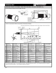
VN12,VN20 Add-on Modules VZN12, VZN20 VZN11, VZN14 VZN05,VZN06<br />
1.83<br />
46.5<br />
2.44 1.89<br />
62<br />
48<br />
2.20<br />
56<br />
<strong>Manual</strong> <strong>Motor</strong> <strong>Control</strong> Switch Mounted on Enclosure Door VN12, VN20<br />
Four Hole Mounting Single Hole Mounting<br />
0.06 to 0.24<br />
1.5 to 6<br />
1.73 2.46<br />
44<br />
62.5<br />
1.75 in x 1.75 in Front Plate (45 mm x 45 mm) 2.38 in x 2.38 in Front Plate (60 mm x 60 mm) Single Hole Mounting<br />
Ø 0.51<br />
Ø 13<br />
1.42<br />
36<br />
1.42 4 x Ø 0.22<br />
36<br />
4 x Ø 5.5<br />
© 1999-2004 <strong>Schneider</strong> <strong>Electric</strong> All Rights Reserved<br />
1.79<br />
45.5<br />
1.54<br />
0.47<br />
39 12<br />
Ø 0.51<br />
Ø 13<br />
1.89<br />
48<br />
1.89<br />
48<br />
0.06 to 0.24<br />
1.5 to 6<br />
4 x Ø 0.22<br />
4 x Ø 5.5<br />
1.73 2.93<br />
44<br />
74.5<br />
1.79<br />
45.5<br />
1.53<br />
0.47<br />
39 12<br />
0.12<br />
3<br />
0.89<br />
22.5<br />
0.50<br />
12.7<br />
Dual Dimensions inches<br />
mm<br />
03/04
Mini-VARIO <strong>and</strong> VARIO <strong>Manual</strong> <strong>Motor</strong> <strong>Control</strong> <strong>Switches</strong><br />
Dimensions <strong>and</strong> Wiring Diagrams<br />
<strong>Manual</strong> <strong>Motor</strong> <strong>Control</strong> Switch Mounted at Back of Enclosure with Shaft Extension VZN17 or VZN30<br />
(clip-on mounting on DIN rail) VN12, VN20<br />
Four Hole Mounting Single Hole Mounting<br />
0.06 to 0.24<br />
1.5 to 6<br />
Enclosures ★ VFN12GE,VFN20GE<br />
★ Enclosures not UL listed.<br />
Wiring Diagrams<br />
e<br />
0.06 to 0.24<br />
1.5 to 6<br />
Switch Body Main Pole Module Neutral Pole Module Auxiliary Contact Blocks<br />
VN12,VN20 VZN12, VZN20 VZN11 VZN05 VZN06<br />
1/L1<br />
2/T1<br />
3/L2<br />
4/T2<br />
5/L3<br />
6/T3<br />
4.17<br />
106<br />
=<br />
=<br />
3.5<br />
90<br />
5.16<br />
131<br />
3.25<br />
82.5<br />
VN12, VN20<br />
03/04 © 1999-2004 <strong>Schneider</strong> <strong>Electric</strong> All Rights Reserved<br />
e<br />
13<br />
14<br />
Shaft<br />
Extension<br />
Distance (e)<br />
Enclosure Depth<br />
in (mm)<br />
VZN17 11.81 to 12.99 (300 to 330)<br />
VZN30 15.75 to 16.93 (400 to 430)<br />
Dual Dimensions inches<br />
mm<br />
22 21<br />
21
Mini-VARIO <strong>and</strong> VARIO <strong>Manual</strong> <strong>Motor</strong> <strong>Control</strong> <strong>Switches</strong><br />
Dimensions <strong>and</strong> Wiring Diagrams<br />
Switch Bodies<br />
V0I, V0 to V2 VZ02 to VZ4, VZ11 to VZ16 VZ7, VZ20<br />
V3 to V6<br />
<strong>Manual</strong> <strong>Motor</strong> <strong>Control</strong> Switch Mounted on Enclosure Door<br />
V0, V0 to V4 Single Hole Mounting Four Hole Mounting<br />
0.06 to 0.24<br />
1.5 to 6<br />
V5 <strong>and</strong> V6 Four Hole Mounting<br />
22<br />
2.36 2.16<br />
60<br />
55<br />
1.73<br />
44<br />
0.06 to 0.24<br />
1.5 to 6<br />
c<br />
c<br />
Ø<br />
G<br />
a<br />
0.06 to 0.24<br />
1.5 to 6<br />
1.46<br />
37<br />
0.06 to 0.24<br />
1.5 to 6<br />
2.91<br />
74<br />
=<br />
H<br />
b<br />
=<br />
2.56 c<br />
1.50 c<br />
65<br />
38.1<br />
© 1999-2004 <strong>Schneider</strong> <strong>Electric</strong> All Rights Reserved<br />
c<br />
c<br />
a<br />
b<br />
1.91<br />
48.5<br />
0.78<br />
20<br />
2.56<br />
65<br />
in (mm) in (mm) in (mm)<br />
a b c<br />
VZ02 <strong>and</strong> VZ01, VZ0 to VZ2, VZ11, VZ14 0.63 (16) 2.9 (74) 1.38 (35)<br />
VZ3, VZ4, VZ12, VZ15 0.79 (20) 3.27 (83) 1.81 (46)<br />
VZ13, VZ16 1.18 (30) 4.92 (125) 2.48 (63)<br />
in (mm) in (mm) in (mm) in (mm) in (mm) in (mm)<br />
a b c G H ∅<br />
V3, V4 2.36 (60) 3.27 (83) 2.56 (65) 1.89 (48) 1.89 (48) 0.22 (5.5)<br />
V5, V6 3.54 (90) 4.92 (125) 3.54 (90) 2.68 (68) 2.68 (68) 0.22 (5.5)<br />
0.06 to 0.24<br />
1.5 to 6<br />
1.42<br />
36<br />
Ø 0.51<br />
Ø 13<br />
2.68<br />
68<br />
c<br />
2.68<br />
68<br />
4 x Ø 0.22<br />
4 x Ø 5.5<br />
0.12<br />
3<br />
0.89<br />
22.5<br />
0.50<br />
12.7<br />
Ø 0.51<br />
Ø 13<br />
1.89<br />
48<br />
1.89<br />
48<br />
in (mm)<br />
c<br />
V0, V0 to V2 2.36 (60)<br />
V3, V4 2.56 (65)<br />
V5, V6 3.54 (90)<br />
4 x Ø 0.22<br />
4 x Ø 5.5<br />
Dual Dimensions inches<br />
mm<br />
03/04
Mini-VARIO <strong>and</strong> VARIO <strong>Manual</strong> <strong>Motor</strong> <strong>Control</strong> <strong>Switches</strong><br />
Dimensions <strong>and</strong> Wiring Diagrams<br />
<strong>Manual</strong> <strong>Motor</strong> <strong>Control</strong> Switch Mounted at back of Enclosure V0, V0 to V2 with Shaft Extension VZ17 or VZ30<br />
(Clip-on mounting on DIN rail possible for V0 to V2)<br />
V0, V0 to V2 V3 to V4 with shaft extension VZ18 or VZ31 V5 <strong>and</strong> V6 with Shaft Extension VZ18 or VZ31<br />
V02 <strong>and</strong> V01<br />
V0 TO V2<br />
V3 AND V4<br />
<strong>Manual</strong> <strong>Motor</strong> <strong>Control</strong> <strong>Switches</strong> for Modular Distribution Boards<br />
VV0 to VV2 VV3 <strong>and</strong> VV4<br />
Enclosures<br />
0.06 to 0.24<br />
1.5 to 6<br />
2.68<br />
68<br />
4.17<br />
106<br />
VF02GE to VF4GE, VFXGE1 to VFXGE4 VF5GE <strong>and</strong> VF6GE ★<br />
c1<br />
★ Enclosures not UL listed.<br />
c<br />
e<br />
Shaft<br />
Extension<br />
Distance (e)<br />
Enc. Back/Door<br />
in (mm)<br />
0.06 to 0.24<br />
1.5 to 6<br />
e<br />
∅<br />
in (mm)<br />
03/04 © 1999-2004 <strong>Schneider</strong> <strong>Electric</strong> All Rights Reserved<br />
2.36<br />
60<br />
G<br />
in (mm)<br />
VZ17 11.81 to 12.99 (300 to 330) 2 x 0.17 (4.2) 0.59 (15)<br />
VZ30 15.75 to 16.93 (400 to 430) 2 x 0.17 (4.2) 0.59 (15)<br />
VZ18 11.81 to 12.99 (300 to 330) 2 x 0.20 (5) 0.79 (20)<br />
VZ31 15.75 to 16.93 (400 to 430) 2 x 0.20 (5) 0.79 (20)<br />
0.22<br />
5.5<br />
1.77<br />
45<br />
∅ 1.77<br />
45<br />
2.91<br />
74<br />
= =<br />
H<br />
b<br />
Ø<br />
4.33<br />
110<br />
G<br />
0.22<br />
5.5<br />
2.83<br />
72<br />
4.96<br />
7.52 126<br />
191<br />
3.7<br />
94<br />
V5 <strong>and</strong> V6<br />
4 x Ø 0.24<br />
6.2<br />
0.06 to 0.24<br />
1.5 to 6<br />
e<br />
Shaft<br />
Extension<br />
2.36<br />
60<br />
Ø 0.28<br />
7<br />
1.18<br />
30<br />
3.93<br />
100<br />
Distance (e)<br />
Enc. Back/Door<br />
in (mm)<br />
VZ18 11.81 to 12.99 (300 to 330)<br />
VZ31 15.75 to 16.93 (400 to 430)<br />
∅1.77<br />
45<br />
3.27<br />
83<br />
7.48<br />
190<br />
8.66<br />
220<br />
= 7.91<br />
=<br />
201<br />
11.02<br />
280<br />
a b c c1 H<br />
VF02GE to VF2GE, VFXGE1 3.54 (90) 5.75 (146) 3.35 (85) 5.16 (131) 5.12 (130)<br />
VF3GE <strong>and</strong> VF4GE,<br />
VFXGE2 <strong>and</strong> VFXGE4<br />
5.91 (150) 6.69 (170) 4.17 (106) 5.98 (152) 6.46 (164) Dual Dimensions inches<br />
mm<br />
23
Mini-VARIO <strong>and</strong> VARIO <strong>Manual</strong> <strong>Motor</strong> <strong>Control</strong> <strong>Switches</strong><br />
Dimensions <strong>and</strong> Wiring Diagrams<br />
Switch Body Main Pole Module Neutral Pole Module Auxiliary Contact Blocks<br />
V02 <strong>and</strong> V01, V0 to V6 VZ02 <strong>and</strong> VZ01, VZ0 to VZ4 VZ11 to VZ13 VZ7 VZ20<br />
Non-Metallic Enclosed Switch Dimensions<br />
Metallic Enclosed Switch Dimensions<br />
NEMA/UL Type 4, 4x, 12<br />
V1W30, V2W30, V1A30, V2A30<br />
24<br />
1/L1<br />
2/T1<br />
7.38<br />
187.3<br />
3/L2<br />
4/T2<br />
5/L3<br />
6/T3<br />
∅ 157.5<br />
6.2<br />
e<br />
b<br />
3.0<br />
76.2<br />
5.5<br />
139.7<br />
d a<br />
6.75<br />
171.5<br />
© 1999-2004 <strong>Schneider</strong> <strong>Electric</strong> All Rights Reserved<br />
c<br />
f<br />
4.5<br />
114.3<br />
6.25<br />
158.8<br />
Type<br />
VC1GU<br />
VC2GU<br />
VC3GU<br />
VC4GU<br />
VC5GU<br />
VC6GU<br />
No. of<br />
Poles<br />
NEMA/UL Type 1<br />
V1G30, V2G30<br />
6.38<br />
174.6<br />
13<br />
14<br />
22 21<br />
a b c d e f<br />
3 6.7 (170) 4.1 (105) 3.2 (82) 4.8 (122) 2.1 (53) 5.0 (128)<br />
3 6.7 (170) 5.3 (135) 3.3 (85) 5.1 (130) 3.7 (95) 5.2 (131)<br />
3 11.0 (280) 8.6 (220) 5.0 (126) 7.9 (201) 7.5 (190) 8.6 (203)<br />
3.0<br />
76.2<br />
5.63<br />
142.9<br />
5.38<br />
136.5<br />
13<br />
14<br />
24 23<br />
4.25<br />
108<br />
5.88<br />
149.2<br />
Dual Dimensions inches<br />
mm<br />
03/04
GS1 Fusible <strong>and</strong> LK3 Non-Fusible Disconnect <strong>Switches</strong><br />
Product Descriptions<br />
Product Description<br />
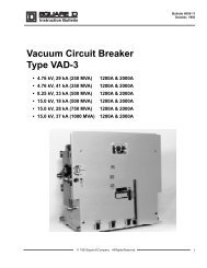
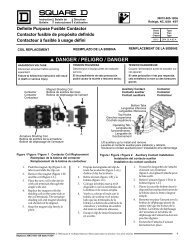
GS1 Fusible Disconnect <strong>Switches</strong> from 30 to 800 A<br />
Definition <strong>and</strong> Function Range Conformity to St<strong>and</strong>ards<br />
The GS1 is a multipolar manually<br />
operated fusible disconnect switch. It<br />
is based on the most up-to-date<br />
disconnect switch technology. The<br />
switch line is tested <strong>and</strong> approved for<br />
use in the most stringent<br />
applications such as “Service<br />
Entrance Rating”.<br />
Product Features<br />
Practical Safeguard<br />
Double Break:<br />
This modern designed mechanism<br />
disconnects on both sides of the<br />
fuse using two double breaking<br />
contacts per pole. This provides<br />
complete isolation of the fuses in the<br />
OFF position.<br />
Touch Safe:<br />
Our design reduces the danger of<br />
accidental contact with live,<br />
energized parts. All products are<br />
supplied st<strong>and</strong>ard with fuse cover.<br />
LK3 Disconnect <strong>Switches</strong> from 30 to 1200 A<br />
Product Features<br />
Seven ratings from 30 to 800 A,<br />
using Class CC, J, <strong>and</strong> L fuses.<br />
Various operations:<br />
St<strong>and</strong>ard, Front<br />
ON-OFF<br />
ON-OFF-Test<br />
Side<br />
A complete line of IEC (DIN, BS or<br />
French ferrule) Fusible disconnect<br />
switches are available from 20 to<br />
1800 A.<br />
UL98<br />
File E191098<br />
CCN WP2X / WP2X7<br />
CSA 22.2 No. 4<br />
File LR 703149<br />
Class 4652 04<br />
IEC 60947-1-3. IEC 60269<br />
CE<br />
UL<br />
File E195721<br />
CNN WHTY2 / WHTY8<br />
Exceptional 200 KA<br />
Short Circuit Protection<br />
The GS1 Series with the use of Class<br />
CC or J fuses provides exceptional high<br />
short circuit protection, up to 200 kA.<br />
Panel Space Savings<br />
This proven switch technology has<br />
the fuses incorporated on the top of<br />
the switch mechanism to reduce<br />
the foot print of the product <strong>and</strong><br />
saves 50% of panel space<br />
compared to other switch designs<br />
using other fuse classes.<br />
Definition <strong>and</strong> Function Range Conformity to St<strong>and</strong>ards<br />
The LK3 is a multipolar manually<br />
operated switch. It is based on the<br />
most up-to date disconnect switch<br />
technology available. Designed<br />
around North American st<strong>and</strong>ard<br />
UL98, it provides a product that<br />
“makes <strong>and</strong> breaks” power circuits<br />
with load. The switch line is tested<br />
<strong>and</strong> approved for use in the most<br />
stringent application such as<br />
“Service Entrance Rating”<br />
Nine ratings from 30 to 1200 A<br />
Various operations:<br />
— Front<br />
— Direct<br />
— Side<br />
Visible blade up to 200 A<br />
Test function available up to 200 A<br />
A complete range of IEC disconnect<br />
switches are available from 20 to<br />
5000 A.<br />
UL98<br />
File E191098<br />
CCN WP2X / WP2X7<br />
CSA 22.2 No. 4<br />
File LR 703149 Class 4652 04<br />
IEC 60947-1-3<br />
CE<br />
UL<br />
File E195721<br />
CNN WTHY2 / WTHY8<br />
Welded Contact Protection Clear Position Indication Visible Internal Contacts<br />
In case of welded contacts due to an<br />
overload or short circuit, the switch<br />
will not reach the OFF position unless<br />
the contacts are actually open.<br />
All switches <strong>and</strong> h<strong>and</strong>les have clear<br />
ON <strong>and</strong> OFF designation.<br />
Additional safety for switches up to<br />
200 A.<br />
03/04 © 1999-2004 <strong>Schneider</strong> <strong>Electric</strong> All Rights Reserved<br />
25
GS1 Fusible <strong>and</strong> LK3 Non-Fusible Disconnect <strong>Switches</strong><br />
Product Descriptions<br />
26<br />
1x 2x 3x<br />
maxi. ø 5 in / 8 mm<br />
16<br />
© 1999-2004 <strong>Schneider</strong> <strong>Electric</strong> All Rights Reserved<br />
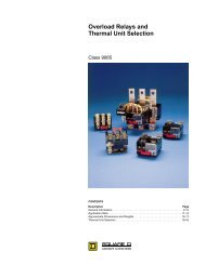
Common Features for Gs1 <strong>and</strong> LK3 Disconnect <strong>Switches</strong><br />
A Complete Range of H<strong>and</strong>les<br />
The GS1/LK3 series offers a full line of NEMA/UL/IP rated h<strong>and</strong>les.<br />
Rated Type 1, 12, 4, <strong>and</strong> 4X<br />
IP54 <strong>and</strong> IP65<br />
All external h<strong>and</strong>les are available in two colors.<br />
Black<br />
Red/Yellow<br />
H<strong>and</strong>les offer the user the largest selection of options in operating the switch.<br />
St<strong>and</strong>ard configuration: ON / OFF (two positions)<br />
Test configuration: ON / OFF / TEST (three positions)<br />
Padlocking<br />
H<strong>and</strong>les can be padlocked in the OFF position with up to three padlocks. Meets<br />
OSHA requirements for lockout / tagout procedures. For safety reasons, the door can<br />
not be opened when the h<strong>and</strong>le is padlocked.<br />
Door Interlock in On Position<br />
The h<strong>and</strong>les allow opening of the door in OFF position only. In the ON position the<br />
door can not be opened. This interlocking can however be by-passed by authorized<br />
personnel.<br />
Defeater<br />
The defeat function allows qualified personnel to by-pass the door interlock when the<br />
switch is in the ON position by means of a tool. This exclusive design is also available<br />
in Type 4 <strong>and</strong> 4X ratings.<br />
Fast <strong>and</strong> Safe Commissioning<br />
The TEST position enables the testing of the control circuit auxiliaries without<br />
switching the main contacts or removing the fuses. This function provides an<br />
alternative to a separately wired push to test button.<br />
03/04
Specifications<br />
GS1 Fusible Disconnect <strong>Switches</strong><br />
UL <strong>and</strong> CSA<br />
Catalog Number<br />
GS1DDU3<br />
(compact)<br />
GS1DU3<br />
(compact)<br />
GS1 Fusible <strong>and</strong> LK3 Non-Fusible Disconnect <strong>Switches</strong><br />
Specifications<br />
GS1EEU3 GS1EU3 GS1GU3 GS1JU3 GS1MU3 GS1QU3 GS1SU3 GS1TU3<br />
Rating A 30 30 30 30 60 100 200 400 600 800<br />
Fuse Type CC J CC J J J J J J L<br />
Operating Voltage<br />
Max HP/Max <strong>Motor</strong> FLA Current<br />
Three Phase<br />
V 600 600 600 600 600 600 600 600 600 600<br />
240V<br />
7.5/22 7.5/22 7.5/22 7.5/22 15/42 30/80 60/154 125/312 250/602 250/602<br />
480V<br />
Hp/A 15/21 15/21 15/21 15/21 30/40 60/77 125/156 250/302 500/590 500/590<br />
600V<br />
20/22 20/22 20/22 20/22 50/52 75/77 150/144 350/336 500/472 500/472<br />
DC 125V<br />
3/25 3/25 3/25 3/25 3/25 7.5/58 15/112 20/148 —<br />
—<br />
DC 250V<br />
5/20 5/20 5/20 5/20 10/38 20/38 40/140(1) 50/173(1) —<br />
—<br />
Short Circuit Rating with Fuses kA 50 50 200 200 200 200 200 200<br />
200<br />
200<br />
Fuse Class<br />
— CC J<br />
CC J<br />
J<br />
J<br />
J<br />
J<br />
J<br />
L<br />
Fuse Rating<br />
Endurance (number of<br />
A<br />
30 30 30 30 60 100 200 400<br />
600<br />
800<br />
operations)<br />
<strong>Electric</strong>al Endurance<br />
Mechanical Endurance<br />
6000<br />
10000<br />
6000<br />
10000<br />
6000<br />
10000<br />
6000<br />
10000<br />
6000<br />
10000<br />
6000<br />
10000<br />
6000<br />
10000<br />
6000<br />
8000<br />
1000<br />
6000<br />
1000<br />
5000<br />
1000<br />
5000<br />
Dimensions 3 Pole H " (mm) 4.56 (116) 4.56 (116) 5.87 (149) 5.87 (149) 5.87 (149) 7.19 (183) 8.12 (206) 14.17 (360) 14.25 (362) 14.25 (362)<br />
W " (mm) 3.8 (97) 4.15 (105) 5.62 (143) 6.72 (171) 6.72 (171) 8.27 (210) 9.45 (240) 11.43 (290) 17.16 (436) 17.16 (436)<br />
D " (mm) 3.3 (84) 3.9 (99) 3.9 (99) 5.63 (143) 5.63 (143) 5.63 (143) 5.99 (152) 5.51 (140) 12.93 (328) 12.93 (328)<br />
Shaft Size Square<br />
in. 0.2 x 0.2 0.2 x 0.2 0.4 x 0.4 0.4 x 0.4 0.4 x 0.4 0.4 x 0.4 0.4 x 0.4 0.4 x 0.4 0.59 x 0.59 0.59 x 0.59<br />
mm 5 x 5 5 x 5 10 x 10 10 x 10 10 x 10 10 x 10 10 x 10 10 x 10 15 x 15 15 x 15<br />
Switch Operating Torque lb. in. 21 21 53 88 88 88 106 132<br />
350<br />
350<br />
Terminal Lug Kits<br />
Wire Range AWG<br />
Wire Tightening<br />
Lug Mounting<br />
Auxiliary Contacts<br />
NEMA/UL Rating, AC<br />
NEMA/UL Rating, DC<br />
min (mm 2 )<br />
max (mm 2 )<br />
lb. in. (Nkm)<br />
lb. in. (Nkm)<br />
A600<br />
N600<br />
St<strong>and</strong>ard<br />
#14 (2)<br />
#10 (6)<br />
27 (3)<br />
Integrated<br />
A600<br />
N600<br />
St<strong>and</strong>ard<br />
#14 (2)<br />
#10 (6)<br />
27 (3)<br />
Integrated<br />
A600<br />
N600<br />
St<strong>and</strong>ard<br />
#14 (2)<br />
#10 (6)<br />
48 (5.4)<br />
Integrated<br />
A600<br />
N600<br />
St<strong>and</strong>ard<br />
#10 (6)<br />
#3 (26)<br />
58 (6.6)<br />
Integrated<br />
A600<br />
N600<br />
St<strong>and</strong>ard<br />
#10m (6)<br />
#3 (26)<br />
58 (6.6)<br />
Integrated<br />
#14 (2)<br />
#2/0 (70)<br />
120 (13.6)<br />
#6 (16)<br />
#3/0 (95)<br />
200 (22.6)<br />
2 x 2 (34)<br />
2 x 600 (304)<br />
MCM<br />
500 (56.5)<br />
2 x 2 (34)<br />
2 x 600 (304)<br />
MCM<br />
500 (56.5)<br />
3 x 2 (34)<br />
3 x 600 (304)<br />
MCM<br />
500 (56.5)<br />
03/04 © 1999-2004 <strong>Schneider</strong> <strong>Electric</strong> All Rights Reserved<br />
A600<br />
N600<br />
A600<br />
N600<br />
(1) 3 Poles in Series in one of the following conditions: 3 poles on +, 2 poles on + <strong>and</strong> 1 on -, 1 pole on + <strong>and</strong> 2 on -, 3 poles on -<br />
IEC<br />
Catalog Number GS1DDU3 GS1DU3 GS1EEU3 GS1EU3 GS1GU3 GS1JU3 GS1MU3‘ GS1QU3 GS1SU3 GS1TU3<br />
Rating A 32 32 32 32 63 100 200 400 630 800<br />
Rated Insulation Voltage Ui V 690 690 750 750 750 750 750 800<br />
1000<br />
1000<br />
Rated Impulse Voltage (Uimp)<br />
8 kV 8 kV 8 kV 8 kV 8 kV 8 kV 8 kV 8 kV<br />
12 kV<br />
12 kV<br />
Operation Current le<br />
A<br />
400 V AC<br />
AC 22A 32 32 32 32 63 100 200 400<br />
630<br />
800<br />
AC 23A 32 32 32 32 63 100 200 400<br />
630<br />
800<br />
690 V AC<br />
AC 22A 32 32 32 32 63 100 200 400<br />
630<br />
800<br />
<strong>Motor</strong> Power (kW)<br />
AC 23A 32 32 32 32 63 100 200 250<br />
630<br />
630<br />
400 V AC<br />
AC 23A 15 15 15 15 30 51 100 220<br />
355<br />
450<br />
500 V AC<br />
AC 23A 18.5 18.5 18.5 18.5 40 63 140 220<br />
450<br />
560<br />
690 V AC<br />
AC 23A 25 25 25 25 55 90 185 220<br />
600<br />
600<br />
Maximum Peak let through<br />
Current<br />
Connection<br />
kA peak 5.5 5.5 7.6 17.6 17.6 22 32 36 77 77<br />
Minimum Cu Cable Section<br />
Minimum Cu Busbar<br />
Section<br />
mm2 mm2 6 6 6 6 10 25 50 185 2 x 150<br />
2 x 40 x 5<br />
A600<br />
N600<br />
A600<br />
N600<br />
27
GS1 Fusible <strong>and</strong> LK3 Non-Fusible Disconnect <strong>Switches</strong><br />
Specifications<br />
LK3 Non-Fusible Disconnect <strong>Switches</strong><br />
UL <strong>and</strong> CSA<br />
Catalog Number LK3DU3 LK3GU3 LK3JU3 LK3MU3 LK3QU3 LK3SU3 LK3TU3 LK3UU3 LK3WU3<br />
Rating A 30 60 100 200 400 600 800 1000 1200<br />
Operating Voltage<br />
Max HP Rating/Max <strong>Motor</strong> FLA Current<br />
Three Phase<br />
V 600 600 600 600 600 600 600 600 600<br />
240V<br />
7.5/22 15/42 30/80 60/154 125/312 200/480 250/602 250/602 250/602<br />
480V<br />
Hp/A 15/21 30/40 60/77 125/156 250/302 400/477 500/590 500/590 500/590<br />
600V<br />
20/22 50/52 75/77 150/144 350/336 350/336 500/472 500/472 500/472<br />
DC 125V<br />
3/25(1) 3/25(1) 7.5/58(1) 15/112(1) 20/148(1) 20/148(1)<br />
DC 250V<br />
5/20(1) 10/38(2) 20/72(2) 40/140(2) 50/173(2) 50/173(2)<br />
Short Circuit Rating with Fuses<br />
Fuse Type<br />
Fuse Rating (A)<br />
Endurances (number of operations)<br />
<strong>Electric</strong>al Endurance<br />
Mechanical Endurance<br />
28<br />
kA<br />
—<br />
A<br />
Dimension 3 Pole H " (mm)<br />
W " (mm)<br />
D " (mm)<br />
Shaft Size Square<br />
Switch Operating Torque<br />
Terminal Lug Kits<br />
Wire Range AWG<br />
Wire Tightening<br />
Lug Mounting<br />
Auxiliary Contacts<br />
NEMA/UL Rating, AC<br />
NEMA/UL Rating, DC<br />
in.<br />
mm<br />
lb. in.<br />
min (mm 2 )<br />
max (mm 2 )<br />
lb. in. (Nkm)<br />
lb. in. (Nkm)<br />
50<br />
CC or J<br />
30<br />
6000<br />
10000<br />
4.57 (116)<br />
3.8 (97)<br />
2.56 (65)<br />
0.2 x 0.2<br />
5 x 5<br />
21<br />
St<strong>and</strong>ard<br />
#14 (2)<br />
#10 (6)<br />
27 (3)<br />
Integrated<br />
A600<br />
N600<br />
© 1999-2004 <strong>Schneider</strong> <strong>Electric</strong> All Rights Reserved<br />
200<br />
J<br />
60<br />
6000<br />
10000<br />
5.87 (149)<br />
6.72 (171)<br />
3.9 (99)<br />
0.4 x 0.4<br />
10 x 10<br />
88<br />
St<strong>and</strong>ard<br />
#10 (6)<br />
#3 (26)<br />
48 (5.4)<br />
Integrated<br />
A600<br />
N600<br />
200<br />
J<br />
100<br />
6000<br />
10000<br />
5.87 (149)<br />
6.72 (171)<br />
3.9 (99)<br />
0.4 x 0.4<br />
10 x 10<br />
88<br />
St<strong>and</strong>ard<br />
#14 (2)<br />
#2/0 (70)<br />
120 (13.4)<br />
Integrated<br />
A600<br />
N600<br />
200<br />
J<br />
200<br />
6000<br />
8000<br />
8.12 (206)<br />
9.45 (240)<br />
3.4 (86)<br />
0.4 x 0.4<br />
10 x 10<br />
106<br />
#6 (16)<br />
3/0 (95)<br />
200 (22.6)<br />
A600<br />
N600<br />
200<br />
J<br />
400<br />
1000<br />
6000<br />
12.6 (320)<br />
11 (279)<br />
6.54 (166)<br />
0.59 x 0.59<br />
15x 15<br />
320<br />
2 x 2 (34)<br />
2 x 600 (304)<br />
MCM<br />
500 (56.5)<br />
(1) 2 Poles in Series<br />
(2) 3 Poles in Series in one of the following conditions: 3 poles on +, 2 poles on + <strong>and</strong> 1 on -, 1 pole on + <strong>and</strong> 2 on -, 3 poles on -<br />
200<br />
J<br />
600<br />
1000<br />
6000<br />
12.6 (320)<br />
11 (279)<br />
6.54 (166)<br />
0.59 x 0.59<br />
15 x 15<br />
320<br />
2 X 2 (34)<br />
2 x 600 (304)<br />
MCM<br />
500 (56.5)<br />
100<br />
L<br />
800<br />
500<br />
3500<br />
13 (320)<br />
14.65 (370)<br />
6.54 (166)<br />
0.59 x 0.59<br />
15 x 15<br />
1320<br />
3 x 2 (34)<br />
3 x 600 (304)<br />
MCM<br />
500 (56.5)<br />
100<br />
L<br />
1000<br />
500<br />
3500<br />
13 (320)<br />
14.65 (370)<br />
6.54 (166)<br />
0.59 x 0.59<br />
15 x 15<br />
320<br />
3 X 2 (34)<br />
3 x 600 (304)<br />
MCM<br />
500 (56.5)<br />
100<br />
L<br />
1200<br />
500<br />
3500<br />
13 (320)<br />
14.65 (370)<br />
6.54 (166)<br />
0.59 x 0.59<br />
15 x 15<br />
320<br />
4 x 2 (34)<br />
4 x 600 (304)<br />
MCM<br />
500 (56.5)<br />
IEC<br />
Catalog Number LK3DU3 LK3GU3 LK3JU3 LK3MU3 LK3QU3 LK3SU3 LK3TU3‘ LK3UU3 LK3WU3<br />
Rating A 32 63 100 200 400 600 800 1000 1250<br />
Rated Insulation Voltage Ui<br />
V 690 750 750 750 1000 1000 1000 1000 1000<br />
Rated Impulse Voltage (Uimp)<br />
8 kV 8 kV 8 kV 8 kV 12 kV 12 kV 12 kV 12 kV 12 kV<br />
Operation Current le<br />
A<br />
400 V AC<br />
AC 22A 32<br />
63<br />
100 200 400<br />
630<br />
800<br />
1000 1200<br />
AC 23A 32<br />
63<br />
100 200 400<br />
630<br />
800<br />
1000 100<br />
690 V AC<br />
AC 22A 32<br />
63<br />
100 200 400<br />
500<br />
630<br />
630<br />
630<br />
<strong>Motor</strong> Power (kW)<br />
AC 23A 32<br />
63<br />
100 200 200<br />
200<br />
400<br />
400<br />
400<br />
400 V AC<br />
AC 23A 15<br />
30<br />
51<br />
100 220<br />
355<br />
450<br />
560<br />
560<br />
500 V AC<br />
AC 23A 18.5 40<br />
63<br />
140 280<br />
450<br />
560<br />
560<br />
560<br />
690 V AC<br />
AC 23A 25<br />
55<br />
90<br />
185 185<br />
185<br />
400<br />
400<br />
400<br />
Maximum Peak let through Current<br />
Connection<br />
kA peak 5.5 17.6 17.6 32 48 48 75 75 75<br />
Minimum Cu Cable Section<br />
mm<br />
Minimum Cu Busbar Section<br />
2<br />
mm2 6 10 25 50 185 2 x 150 2 x 185 2 x 240<br />
2 x 30 x 5 2 x 40 x 5 2 x 50 x 5 2 x 60 x 5<br />
03/04
SELECT ONE OF EACH<br />
GS1 Fusible <strong>and</strong> LK3 Non-Fusible Disconnect <strong>Switches</strong><br />
Selection<br />
Selection<br />
1 SWITCH + 1 SHAFT + 1 HANDLE + 1 LUG KIT (IF REQUIRED)<br />
(see below) (see pages 31 & 32) (see pages 31 & 32) (see page 33)<br />
Compact 30A Switch Shaft 320mm Black H<strong>and</strong>le Lug Kit<br />
GS1DDU3 GS1AE2 GS1AH130 GS1AW403<br />
200A Switch<br />
GS1MU3<br />
800A Switch<br />
GS1TU3<br />
30A Side H<strong>and</strong>le<br />
GS1EERU30<br />
Fusible Disconnect <strong>Switches</strong><br />
Compact GS1 30 A<br />
Type Fuses Amps Nb<br />
Maximum Horse Power Rating<br />
Three Phase Test Function Catalog<br />
Number<br />
Poles 240 V 480 V 600 V<br />
Compact<br />
Fused<br />
CC 30 3 7.5 15 20 Yes* GS1DDU3<br />
Compact<br />
Fused<br />
J 30 3 7.5 15 20 Yes* GS1DU3<br />
* Test function is available as st<strong>and</strong>ard but can only be active with test h<strong>and</strong>le.<br />
GS1 30 to 400 A<br />
Type Fuses Amps Nb<br />
Maximum Horse Power Rating<br />
Three Phase Test Function Catalog<br />
Number<br />
Poles 240 V 480 V 600 V<br />
Fused CC 30 3 7.5 15 20 Yes* GS1EEU3<br />
Fused J 30 3 7.5 15 20 Yes* GS1EU3<br />
Fused J 60 3 15 30 50 Yes* GS1GU3<br />
Fused J 100 3 30 60 75 Yes* GS1JU3 s<br />
Fused J 200 3 60 125 150 Yes* GS1MU3 s<br />
Fused J 400 3 125 250 350 Yes* GS1QU3 s<br />
* Test function is available as st<strong>and</strong>ard but can only be active with test h<strong>and</strong>le.<br />
GS1 600 to 800 A<br />
Type Fuses Amps Nb<br />
Maximum Horse Power Rating<br />
Three Phase Test Function Catalog<br />
Number<br />
Poles 240 V 480 V 600 V<br />
Fused J 600 3 250 500 500 No GS1SU3 s<br />
Fused L 800 3 250 500 500 No GS1TU3 s<br />
For H<strong>and</strong>les <strong>and</strong> Shafts, see pages 31 & 32.<br />
s Terminal lugs must be ordered separately.<br />
With Direct Mount Side H<strong>and</strong>le<br />
Type Fuses Amps Nb Three Phase<br />
Maximum Horse Power Rating<br />
Test<br />
Function<br />
03/04 © 1999-2004 <strong>Schneider</strong> <strong>Electric</strong> All Rights Reserved<br />
Catalog<br />
Number<br />
Poles 240 V 480 V 600 V<br />
Fused CC 30 2 – – – No GS1EERU20<br />
Fused CC 30 3 7.5 15 20 No GS1EERU30<br />
29
GS1 Fusible <strong>and</strong> LK3 Non-Fusible Disconnect <strong>Switches</strong><br />
Selection<br />
SELECT ONE OF EACH<br />
30<br />
1 SWITCH + 1 SHAFT + 1 HANDLE + 1 LUG KIT (IF REQUIRED)<br />
(see below) (see pages 31 & 32) (see pages 31 & 32) (seepage 33)<br />
800A Switch Shaft 200mm Black H<strong>and</strong>le Lug Kit<br />
LK3TU3 GS1AE6 LK3AH150 GS1AW503<br />
Compact 30A Switch<br />
LK3DU3<br />
200A Switch<br />
LK3MU3<br />
600A Switch<br />
LK3SU3<br />
© 1999-2004 <strong>Schneider</strong> <strong>Electric</strong> All Rights Reserved<br />
Non-Fusible Disconnect <strong>Switches</strong><br />
LK3 30 A<br />
Type Amps Nb<br />
Maximum Horsepower Rating<br />
Three Phase Test Function Catalog<br />
Number<br />
Compact Poles 240 V 480 V 600 V<br />
Non-Fused 30 3 7.5 15 20 Yes* LK3DU3<br />
* Test function is available as st<strong>and</strong>ard but can only be active with test h<strong>and</strong>le.<br />
LK3 60 to 200 A<br />
Type Amps Nb<br />
Maximum Horsepower Rating<br />
Three Phase Test Function Catalog<br />
Number<br />
Poles 240 V 480 V 600 V<br />
Non-Fused 60 3 15 30 50 Yes* LK3GU3<br />
Non-Fused 100 3 30 60 75 Yes* LK3JU3 s<br />
Non-Fused 200 3 60 125 150 Yes* LK3MU3 s<br />
* Test function is available as st<strong>and</strong>ard but can only be active with test h<strong>and</strong>le.<br />
LK3 400 to1200 A<br />
Type Amps Nb<br />
Maximum Horsepower Rating<br />
Three Phase Test Function Catalog<br />
Number<br />
Poles 240 V 480 V 600 V<br />
Non-Fused 400 3 125 250 350 No LK3QU3 s<br />
Non-Fused 600 3 200 400 350 No LK3SU3 s<br />
Non-Fused 800 3 250 500 500 No LK3TU3 s<br />
Non-Fused 1000 3 250 500 500 No LK3UU3 s<br />
Non-Fused 1200 3 250 500 500 No LK3WU3 s<br />
For H<strong>and</strong>les <strong>and</strong> Shafts, see pages 31 & 32.<br />
s Terminal lugs must be ordered separately.<br />
03/04
Economical H<strong>and</strong>le Design<br />
St<strong>and</strong>ard H<strong>and</strong>le Design<br />
Type D<br />
GS1AH101 GS1AH102<br />
Compact Shaft Kits GS1AE7/AE71<br />
Type G<br />
5 mm x 5 mm<br />
GS1AH110 GS1AH120<br />
Compact Shaft Kits GS1AE8/AE81<br />
GS1AH110<br />
GS1AH120<br />
5 mm x 5 mm<br />
GS1 Fusible <strong>and</strong> LK3 Non-Fusible Disconnect <strong>Switches</strong><br />
Selection of H<strong>and</strong>les <strong>and</strong> Shafts<br />
Selection of H<strong>and</strong>les <strong>and</strong> Shafts<br />
For Compact GS1 <strong>and</strong> LK3<br />
Pistol H<strong>and</strong>les, Type D<br />
NEMA/UL<br />
Type<br />
1, 12<br />
1, 12<br />
IEC Type Defeatable Padlockable Color Operation<br />
H<strong>and</strong>les UL approved for indoor <strong>and</strong> outdoor applications.<br />
03/04 © 1999-2004 <strong>Schneider</strong> <strong>Electric</strong> All Rights Reserved<br />
IP54<br />
IP54<br />
Yes<br />
Yes<br />
Yes<br />
Yes<br />
Black<br />
Red/Yellow<br />
Off/On (O/I)<br />
Off/On (O/I)<br />
Shaft Kits 5 mm (0.2") x 5 mm (0.2") — For use with Pistol H<strong>and</strong>les, Type D<br />
Shaft Length<br />
(Inches/mm)<br />
12.6/320<br />
15.7/400<br />
Pistol H<strong>and</strong>les, Type G<br />
NEMA/UL<br />
Type<br />
1, 12<br />
1, 12<br />
1, 12<br />
1, 12<br />
1, 4, 4X, 12<br />
1, 4, 4X, 12<br />
1, 4, 4X, 12<br />
1, 4, 4X, 12<br />
IEC Type Defeatable Padlockable Color Operation<br />
IP54<br />
IP54<br />
IP54<br />
IP54<br />
IP65<br />
IP65<br />
IP65<br />
IP65<br />
Yes<br />
Yes<br />
Yes<br />
Yes<br />
Yes<br />
Yes<br />
Yes<br />
Yes<br />
Yes<br />
Yes<br />
Yes<br />
Yes<br />
Yes<br />
Yes<br />
Yes<br />
Yes<br />
Black<br />
Red/Yellow<br />
Black<br />
Red/Yellow<br />
Black<br />
Red/Yellow<br />
Black<br />
Red/Yellow<br />
Off/On (O/I)<br />
Off/On (O/I)<br />
Test/Off/On(T/O/I)<br />
Test/Off/On(T/O/I)<br />
Off/On (O/I)<br />
Off/On (O/I)<br />
Test/Off/On(T/O/I)<br />
Test/Off/On(T/O/I)<br />
Shaft Kits 5 mm (0.2") x 5 mm (0.2") — For use with Pistol H<strong>and</strong>les, Type G<br />
Shaft Length<br />
(Inches/mm)<br />
12.6/320<br />
15.7/400<br />
H<strong>and</strong>les UL approved for indoor <strong>and</strong> outdoor applications.<br />
H<strong>and</strong>les for St<strong>and</strong>ard GS1 <strong>and</strong> LK3 (as listed below)<br />
Pistol H<strong>and</strong>les - GS1 30 A through 100 A <strong>and</strong> LK3 60 A through 100 A<br />
NEMA/UL<br />
Type<br />
IEC Type Defeatable Padlockable Color Operation<br />
1, 12<br />
1, 12<br />
1, 12<br />
1, 12<br />
1, 4, 4X, 12<br />
1, 4, 4X, 12<br />
1, 4, 4X, 12<br />
1, 4, 4X, 12<br />
IP54<br />
IP54<br />
IP54<br />
IP54<br />
IP65<br />
IP65<br />
IP65<br />
IP65<br />
Yes<br />
Yes<br />
Yes<br />
Yes<br />
Yes<br />
Yes<br />
Yes<br />
Yes<br />
Yes<br />
Yes<br />
Yes<br />
Yes<br />
Yes<br />
Yes<br />
Yes<br />
Yes<br />
Black<br />
Red/Yellow<br />
Black<br />
Red/Yellow<br />
Black<br />
Red/Yellow<br />
Black<br />
Red/Yellow<br />
Pistol H<strong>and</strong>les - GS1 200 A through 400 A <strong>and</strong> LK3 200 A<br />
NEMA/UL<br />
Type<br />
1, 12<br />
1, 12<br />
1, 12<br />
1, 12<br />
1, 4, 4X, 12<br />
1, 4, 4X, 12<br />
1, 4, 4X, 12<br />
1, 4, 4X, 12<br />
Off/On (O/I)<br />
Off/On (O/I)<br />
Test/Off/On(T/O/I)<br />
Test/Off/On(T/O/I)<br />
Off/On (O/I)<br />
Off/On (O/I)<br />
Test/Off/On(T/O/I)<br />
Test/Off/On(T/O/I)<br />
IEC Type Defeatable Padlockable Color Operation<br />
IP54<br />
IP54<br />
IP54<br />
IP54<br />
IP65<br />
IP65<br />
IP65<br />
IP65<br />
Yes<br />
Yes<br />
Yes<br />
Yes<br />
Yes<br />
Yes<br />
Yes<br />
Yes<br />
Shaft Kits 10 mm (0.4") x 10 mm (0.4")<br />
Shaft Length<br />
(Inches/mm)<br />
12.6/320<br />
15.7/400<br />
Yes<br />
Yes<br />
Yes<br />
Yes<br />
Yes<br />
Yes<br />
Yes<br />
Yes<br />
Black<br />
Red/Yellow<br />
Black<br />
Red/Yellow<br />
Black<br />
Red/Yellow<br />
Black<br />
Red/Yellow<br />
On/Off & O/I<br />
On/Off & O/I<br />
Test/Off/On(T/O/I)<br />
Test/Off/On(T/O/I)<br />
On/Off & O/I<br />
On/Off & O/I<br />
Test/Off/On(T/O/I)<br />
Test/Off/On(T/O/I)<br />
Catalog<br />
Number<br />
GS1AH101<br />
GS1AH102<br />
Catalog<br />
Number<br />
GS1AE7<br />
GS1AE71<br />
Catalog<br />
Number<br />
GS1AH110<br />
GS1AH120<br />
GS1AHT110<br />
GS1AHT120<br />
GS1AH410<br />
GS1AH420<br />
GS1AHT410<br />
GS1AHT420<br />
Catalog<br />
Number<br />
GS1AE8<br />
GS1AE81<br />
Catalog<br />
Number<br />
GS1AH110<br />
GS1AH120<br />
GS1AHT110<br />
GS1AHT120<br />
GS1AH410<br />
GS1AH420<br />
GS1AHT410<br />
GS1AHT420<br />
Catalog<br />
Number<br />
GS1AH130<br />
GS1AH140<br />
GS1AHT130<br />
GS1AHT140<br />
GS1AH430<br />
GS1AH440<br />
GS1AHT430<br />
GS1AHT440<br />
Catalog<br />
Number<br />
GS1AE2<br />
GS1AE21<br />
31
GS1 Fusible <strong>and</strong> LK3 Non-Fusible Disconnect <strong>Switches</strong><br />
Selection of H<strong>and</strong>les <strong>and</strong> Shafts<br />
32<br />
LK3AH160 GS1 AE6<br />
GS1AH160<br />
GS1AE6<br />
© 1999-2004 <strong>Schneider</strong> <strong>Electric</strong> All Rights Reserved<br />
For LK3 400 A through 1200 A<br />
Pistol H<strong>and</strong>les — For use with Shaft Type H<br />
NEMA/UL<br />
Type<br />
1, 4, 4X, 12<br />
1, 4, 4X, 12<br />
1, 4, 4X, 12<br />
1, 4, 4X, 12<br />
IEC Type Defeatable Padlockable Color Operation<br />
IP65<br />
IP65<br />
IP65<br />
IP65<br />
No<br />
No<br />
Yes<br />
Yes<br />
Yes<br />
Yes<br />
Yes<br />
Yes<br />
Black<br />
Red/Yellow<br />
Black<br />
Red/Yellow<br />
Off/On (O/I)<br />
Off/On (O/I)<br />
Off/On (O/I)<br />
Off/On (O/I)<br />
Shaft 15 mm (0.6") x 15 mm (0.6") — For use with Pistol H<strong>and</strong>les, Type H<br />
Shaft Length<br />
(Inches/mm)<br />
7.9/200<br />
15.7/400<br />
H<strong>and</strong>les UL approved for indoor <strong>and</strong> outdoor applications.<br />
For GS1 600 A through 800 A<br />
Pistol H<strong>and</strong>les — For use with Type H<br />
NEMA/UL<br />
Type<br />
IEC Type Defeatable Padlockable Color Operation<br />
1, 4, 4X, 12 IP65 No<br />
Yes<br />
Black Off/On (O/I)<br />
1, 4, 4X, 12 IP65 No<br />
Yes<br />
Red/Yellow Off/On (O/I)<br />
1, 4, 4X, 12 IP65 Yes<br />
Yes<br />
Black Off/On (O/I)<br />
1, 4, 4X, 12 IP65 Yes<br />
Yes<br />
Red/Yellow Off/On (O/I)<br />
Shaft 15 mm (0.6") x 15 mm (0.6") — For use with Pistol H<strong>and</strong>les, Type H<br />
Shaft Length<br />
(Inches/mm)<br />
7.9/200<br />
15.7/400<br />
H<strong>and</strong>les UL approved for indoor <strong>and</strong> outdoor applications.<br />
Other Products as Special Order:<br />
2 Pole <strong>Switches</strong><br />
4 Pole <strong>Switches</strong><br />
Mixed Poles ❆<br />
Flange Operation ❆<br />
Direct Operation ❆<br />
❆ Consult Square D for pricing <strong>and</strong> availability.<br />
Catalog<br />
Number<br />
LK3AH150<br />
LK3AH160<br />
LK3AH170<br />
LK3AH180<br />
Catalog<br />
Number<br />
GS1AE6<br />
GS1AE61<br />
Catalog<br />
Number<br />
LK3AH150<br />
LK3AH160<br />
GS1AH170<br />
GS1AH180<br />
Catalog<br />
Number<br />
GS1AE6<br />
GS1AE61<br />
03/04
GS1AM110 installed<br />
on GS1AD20<br />
Terminal Shrouds<br />
GS1AM110<br />
?<br />
Terminal Lugs<br />
GS1 Fusible <strong>and</strong> LK3 Non-Fusible Disconnect <strong>Switches</strong><br />
Accessories<br />
Accessories<br />
Auxiliary Contacts<br />
For Compact LK3 or GS1 30 A<br />
Type Description<br />
Top mounted<br />
10 A<br />
600 VAC<br />
St<strong>and</strong>ard products allow up to 4 auxiliary contacts without any<br />
extra contact holders.<br />
1 N.O. Contact Block<br />
1 N.C. Contact Block<br />
Additional auxiliary contact holder<br />
For LK3 60 A through 200 A — GS1 (non-compact) 30 A through 400 A<br />
Type Description<br />
Top mounted<br />
10 A<br />
600 VAC<br />
S = side mounted q<br />
S = side mounted q<br />
For LK3 400 A to 1200 A<br />
Type Description<br />
Top mounted<br />
10 A<br />
600 VAC<br />
For GS1 600 A to 800 A<br />
Type Description<br />
1 N.O./N.C. Contact<br />
Micro-switch<br />
2 N.O./N.C. Contact<br />
q Cannot mix GS1AN with GS1NT.<br />
Terminal Lugs Kit<br />
For use on<br />
Contact holder required (for 1 to 8 upper auxiliary contacts)<br />
1 N.O. Contact Block<br />
1 N.C. Contact Block<br />
1 N.O. & N.C. Contact Block (max of two blocks - any mix)<br />
2 N.O. & N.C. Contact Block (max of two blocks - any mix)<br />
1 N.O. & N.C. Contact Block w/ Test (max of two blocks - any mix)<br />
2 N.O. & N.C. Contact Block w/ Test (max of two blocks - any mix)<br />
Contact holder (for 1 to 4 auxiliary contacts)<br />
1 N.O. Contact Block<br />
1 N.C. Contact Block<br />
Wire Size<br />
AWG (mm 2 )<br />
# of Wires<br />
per Lug<br />
Catalog<br />
Number<br />
GS1AM110<br />
GS1AM101<br />
GS1AD10<br />
Catalog<br />
Number<br />
GS1AD20<br />
GS1AM110<br />
GS1AM101<br />
GS1AN11<br />
GS1AN22<br />
GS1ANT11<br />
GS1ANT22<br />
Catalog<br />
Number<br />
LK3AD30<br />
GS1AM110<br />
GS1AM101<br />
Catalog<br />
Number<br />
GS1AMU3<br />
GS1AMU4<br />
03/04 © 1999-2004 <strong>Schneider</strong> <strong>Electric</strong> All Rights Reserved<br />
Wire<br />
Type<br />
Lugs per<br />
Kit<br />
Catalog<br />
Number<br />
Compact GS1/LK3 #14 (2.1)- #10 (6) 1 Cu — St<strong>and</strong>ard<br />
GS1 30 A CC<br />
GS1 30 A J<br />
GS1/LK3 60 A J<br />
LK3 100 A<br />
GS1 100 A<br />
GS1/LK3 200 A<br />
GS1/LK3 400 to 600 A ●<br />
GS1/LK3 800 A / LK3 1000 A ●<br />
LK3 1250 A ●<br />
#14 (2.1)- #10 (6)<br />
#14 (2.1)- #10 (6)<br />
#10 (6) - #3 (26)<br />
#14 (2.1)- #2/0 (70)<br />
#14 (2.1) - 2/0 (70)<br />
#6 (16) - 3/0 (95)<br />
2 x 2 (34) - 2 x 600 (304)<br />
3 x 2 (34) - 3 x 600 (304)<br />
4 x 2 (34) - 4 x 600 (304)<br />
1<br />
1<br />
1<br />
1<br />
1<br />
1<br />
2<br />
3<br />
2<br />
Cu<br />
Cu<br />
Cu<br />
Cu<br />
Cu/Al<br />
Cu/Al<br />
Cu/Al<br />
Cu/Al<br />
Cu/Al<br />
—<br />
—<br />
—<br />
—<br />
6<br />
6<br />
6<br />
6<br />
12<br />
St<strong>and</strong>ard<br />
St<strong>and</strong>ard<br />
St<strong>and</strong>ard<br />
St<strong>and</strong>ard<br />
GS1AW303<br />
GS1AW403<br />
GS1AW503<br />
GS1AW803<br />
GS1AW903<br />
● GS1 600 A-800 A <strong>and</strong> LK3 800 A-1250 A can receive 1 lug for 3 cables per terminal or 2 lugs for 2 cables per<br />
terminal.<br />
Power Distribution Lugs<br />
For use on<br />
GS1JU3<br />
GS1MU3<br />
GS1QU3<br />
GS1MU3<br />
GS1QU3<br />
Terminal Shrouds<br />
For Line or Load Side ¥<br />
For use on<br />
Wire Size<br />
AWG (mm 2 )<br />
#8 (10) - #6 (16)<br />
#14 (2.1)- #10 (6)<br />
#2 (35)- #2/0 (70)<br />
#6 (16) - #4 (25)<br />
#8 (10)<br />
#12 (3.3) - #10 (4)<br />
#6 (16) - #4 (35)<br />
#8 (10)<br />
#14 (2.1)- #10 (6)<br />
# of Wires<br />
per Lug<br />
Compact GS1/LK3<br />
All GS1/LK3 30 A<br />
ALL GS1/LK3 60 A<br />
LK3 100 A<br />
GS1 100 A †<br />
GS1/LK3 200 A †<br />
GS1 400 A<br />
LK3 400 A to 600 A<br />
GS1 600 A to 800 A<br />
LK3 800 A to 1250 A<br />
† Three piece kit for either line or load side.<br />
¥ All GS1 <strong>and</strong> LK3 switches supplied with line side shrouding.<br />
6<br />
12<br />
6<br />
Wire<br />
Type<br />
Cu<br />
Cu<br />
Cu<br />
Cu<br />
Cu<br />
Cu<br />
Cu<br />
Cu<br />
Cu<br />
Lugs per<br />
Kit<br />
Catalog<br />
Number<br />
3 GS1AW306<br />
3 GS1AW406<br />
3 GS1AW506<br />
Catalog<br />
Number<br />
St<strong>and</strong>ard<br />
St<strong>and</strong>ard<br />
St<strong>and</strong>ard<br />
St<strong>and</strong>ard<br />
GS1AP33<br />
GS1AP43<br />
GS1AP63<br />
LK3AP63<br />
GS1AP83<br />
LK3AP83<br />
33
GS1 Fusible <strong>and</strong> LK3 Non-Fusible Disconnect <strong>Switches</strong><br />
Accessories<br />
34<br />
Shorting Links<br />
© 1999-2004 <strong>Schneider</strong> <strong>Electric</strong> All Rights Reserved<br />
Shorting Links<br />
For use on Shorting Links per Kit<br />
GS1 60 A<br />
GS1 100 A<br />
GS1 200 A<br />
GS1 400 A<br />
GS1 600 to 800 A<br />
Shaft Padlocking Kit<br />
For use on<br />
Compact GS1/LK3<br />
LK3 60 A to 200 A<br />
GS1 30 A to 400 A<br />
LK3 400 A to 1250 A<br />
GS1 600 A <strong>and</strong> 800 A<br />
3<br />
3<br />
3<br />
3<br />
3<br />
Catalog<br />
Number<br />
GS1AU203<br />
GS1AU303<br />
GS1AU403<br />
GS1AU503<br />
GS1AU803<br />
Catalog<br />
Number<br />
St<strong>and</strong>ard<br />
St<strong>and</strong>ard<br />
St<strong>and</strong>ard<br />
St<strong>and</strong>ard<br />
GS1AXU3<br />
03/04
Dimensions<br />
GS1<br />
GS1 Fusible <strong>and</strong> LK3 Non-Fusible Disconnect <strong>Switches</strong><br />
Dimensions for GS1<br />
GS1DDU3 Compact GS1 30 A CC<br />
4.56<br />
116<br />
FIX<br />
3.13<br />
79.5<br />
0.78<br />
45<br />
0.72<br />
18.3<br />
3.75<br />
96.5<br />
1.47<br />
37.3<br />
Mounting<br />
ø 0.19<br />
0.59<br />
15<br />
5.6<br />
1.0<br />
GS1DU3 Compact GS1 30 A J<br />
4.56<br />
116<br />
FIX<br />
3.38<br />
84<br />
0.63<br />
15.8<br />
4.13<br />
105.5<br />
1.47<br />
.059<br />
37.3 15<br />
Mounting<br />
ø 0.19<br />
1.0<br />
28<br />
1.83<br />
46.5<br />
03/04 © 1999-2004 <strong>Schneider</strong> <strong>Electric</strong> All Rights Reserved<br />
1.83<br />
46.5<br />
63<br />
2<br />
2<br />
3.25<br />
83.8<br />
3.88<br />
99<br />
2.5<br />
65<br />
2.5<br />
65<br />
0.13<br />
2 ø 4.5<br />
1.25<br />
ø 31<br />
1.25<br />
ø 31<br />
3<br />
5<br />
DOOR DRILLING<br />
-ON<br />
DOOR DRILLING<br />
-ON<br />
2.0<br />
50<br />
90<br />
2.0<br />
50<br />
90<br />
-OFF<br />
-OFF<br />
Dual Dimensions inches<br />
Dual Dimensions<br />
mm<br />
inches<br />
mm<br />
35
GS1 Fusible <strong>and</strong> LK3 Non-Fusible Disconnect <strong>Switches</strong><br />
Dimensions for GS1<br />
GS1EEU3 GS1 30 A CC<br />
5.88<br />
149.2<br />
GS1EU3 / GS1GU3 GS1 30 A / 60 A J<br />
149.2<br />
5.88<br />
36<br />
Mounting<br />
1.13<br />
29<br />
1.5<br />
38.2<br />
6.75<br />
170.8<br />
5.69<br />
144<br />
2.44<br />
61.5<br />
2.75<br />
69.7<br />
66.7<br />
2.63<br />
66.7<br />
2.63<br />
© 1999-2004 <strong>Schneider</strong> <strong>Electric</strong> All Rights Reserved<br />
FIX<br />
FIX<br />
133.4<br />
5.25<br />
133.4<br />
5.25<br />
5.0<br />
126.5<br />
5.0<br />
126.5<br />
2.75<br />
70<br />
2.75<br />
70<br />
3.88<br />
99<br />
5.63<br />
142.8<br />
3.5<br />
89.2<br />
2.0<br />
0.13<br />
50 TEST POSITION<br />
4 ø 4.5<br />
65<br />
2.0<br />
50<br />
1.25<br />
ø 31<br />
2.0<br />
50<br />
DOOR DRILLING<br />
-ON<br />
o<br />
90<br />
o<br />
90<br />
-OFF<br />
0.13<br />
4 ø 4.5<br />
2.0<br />
50 TEST POSITION<br />
65<br />
1.25<br />
ø 31<br />
DOOR DRILLING<br />
-ON<br />
-OFF<br />
Dual Dimensions inches<br />
mm<br />
03/04
GS1 Fusible <strong>and</strong> LK3 Non-Fusible Disconnect <strong>Switches</strong><br />
Dimensions for GS1<br />
GS1JU3 GS1 100 A J<br />
182.6<br />
7.19<br />
2.06<br />
52<br />
8.25<br />
210<br />
3.31<br />
83.5<br />
3.31<br />
83.4<br />
FIX<br />
166.7<br />
6.56<br />
5.0<br />
126.5<br />
2.75<br />
70<br />
DOOR DRILLING TERMINAL LUGS 2/0 max<br />
DOOR DRILLING TERMINAL LUGS 2/0 max<br />
GS1MU3 GS1 200 A J<br />
206.4<br />
8.13<br />
Mounting<br />
2.44<br />
62<br />
9.44<br />
240<br />
3.69<br />
93.5<br />
3.75<br />
95.2<br />
190.5<br />
7.5<br />
FIX<br />
5.0<br />
126.5<br />
2.75<br />
70<br />
03/04 © 1999-2004 <strong>Schneider</strong> <strong>Electric</strong> All Rights Reserved<br />
5.63<br />
143.2<br />
3.44<br />
86.6<br />
6.0<br />
152.4<br />
3.44<br />
86.6<br />
0.13<br />
4 ø 4.5<br />
2.0<br />
50 TEST POSITION<br />
65<br />
2.0<br />
50<br />
1.25<br />
ø 31<br />
0.13<br />
4 ø 4.5<br />
2.0<br />
50<br />
-ON<br />
o<br />
90<br />
65<br />
o<br />
90<br />
-OFF<br />
0.88<br />
22.3<br />
1.5<br />
38.8<br />
1.25<br />
6.9<br />
0.63<br />
15.4<br />
0.75<br />
19.8<br />
DOOR DRILLING TERMINAL LUGS 3/0ma<br />
1.25<br />
ø 31<br />
2.0<br />
50<br />
-ON<br />
TEST POSITION<br />
-OFF<br />
0.44<br />
11.6<br />
1.13<br />
1.0<br />
28.6<br />
25<br />
Dual Dimensions inches<br />
mm<br />
37
GS1 Fusible <strong>and</strong> LK3 Non-Fusible Disconnect <strong>Switches</strong><br />
Dimensions for GS1<br />
GS1QU3 GS1 400 A J<br />
14.31<br />
363.6<br />
GS1SU3/GS1TU3 GS1 600 A J <strong>and</strong> 800 A L<br />
492.1<br />
19.38<br />
38<br />
0.38<br />
9<br />
2.5<br />
65<br />
FIX.<br />
14.25<br />
362<br />
9.88<br />
250<br />
6.0<br />
152<br />
2.38<br />
59<br />
Mounting<br />
2.81<br />
72.1<br />
11.94<br />
303<br />
Mounting 13.63<br />
4.75<br />
120<br />
2.81<br />
72.1<br />
344.5<br />
Mounting 9.88<br />
250<br />
4.75<br />
120<br />
20.38<br />
516.9<br />
2.06<br />
51.9<br />
4.0<br />
100.4<br />
112.1<br />
4.44<br />
1.5<br />
38.8<br />
224.2<br />
8.81<br />
© 1999-2004 <strong>Schneider</strong> <strong>Electric</strong> All Rights Reserved<br />
FIX<br />
0.25<br />
LOCKING 55<br />
179.8<br />
7.13<br />
5.0<br />
126.5<br />
190<br />
7.5<br />
3.88<br />
98<br />
2.75<br />
70<br />
5.56<br />
141.4<br />
3.13<br />
79.5<br />
Dual Dimensions inches<br />
mm<br />
3.44<br />
87<br />
0.5<br />
11.8<br />
0.25<br />
6.8<br />
7.5<br />
189.8<br />
0.13<br />
4 ø 4.5<br />
2.0<br />
50 TEST POSITION<br />
65<br />
2.0<br />
50<br />
1.25<br />
ø 31<br />
4.13<br />
106.1<br />
2.75<br />
68.5<br />
DOOR DRILLING TERMINAL LUGS<br />
2x600 MCM max<br />
-ON<br />
DOOR DRILLING<br />
3.13<br />
80<br />
0.38<br />
10.2<br />
o<br />
90<br />
-OFF<br />
2.0<br />
50<br />
0.13<br />
4.5<br />
1.25<br />
38<br />
2.88<br />
73<br />
3.13<br />
80<br />
2.0<br />
50<br />
0.44<br />
11<br />
0.38<br />
1.25<br />
TERMINAL LUGS<br />
2X600 MCM max 3x600 MCM max<br />
3.56<br />
90.5<br />
31<br />
10.2<br />
1.56<br />
16<br />
3.0<br />
76<br />
1.5<br />
38<br />
2.88<br />
73<br />
2.5<br />
63<br />
03/04
Dimensions for LK3<br />
LK3<br />
GS1 Fusible <strong>and</strong> LK3 Non-Fusible Disconnect <strong>Switches</strong><br />
Dimensions for LK3<br />
LK3DU3 Compact LK3 30 A<br />
4.56<br />
116<br />
3.13<br />
79.5<br />
FIX<br />
1.78<br />
45<br />
0.72<br />
18.3<br />
3.78<br />
96<br />
1.47<br />
37.3<br />
Mounting<br />
0.19<br />
0.59<br />
15<br />
25.6<br />
1.0<br />
0.56<br />
14<br />
1.83<br />
46.5<br />
LK3GU3 / LK3JU3 LK3 60 A / 100 A<br />
149.2<br />
5.88<br />
0.19<br />
5.2<br />
Mounting<br />
1.5<br />
38.2<br />
6.69<br />
170.6<br />
2.75<br />
69.7<br />
2.63<br />
66.7<br />
133.4<br />
5.25<br />
FIX<br />
5.0<br />
126.5<br />
03/04 © 1999-2004 <strong>Schneider</strong> <strong>Electric</strong> All Rights Reserved<br />
2.75<br />
70<br />
2.48<br />
63<br />
3.84<br />
98<br />
1.0<br />
25.4<br />
3.5<br />
89.2<br />
0.75<br />
19<br />
3.88<br />
99<br />
2.59<br />
66<br />
0.13<br />
2 ø 4.5<br />
1.25<br />
ø 31<br />
2.0<br />
50<br />
DOOR DRILLING<br />
-ON<br />
2.0<br />
50<br />
90<br />
o<br />
90<br />
-OFF<br />
0.13<br />
4 ø 4.5<br />
2.0<br />
50 TEST POSITION<br />
65<br />
1.25<br />
ø<br />
31<br />
DOOR DRILLING<br />
-ON<br />
-OFF<br />
Dual Dimensions inches<br />
mm<br />
39
GS1 Fusible <strong>and</strong> LK3 Non-Fusible Disconnect <strong>Switches</strong><br />
Dimensions for LK3<br />
LK3MU3 LK3 200 A<br />
206.4<br />
8.13<br />
LK3QU3 / LK3SU3 LK3 400 A / 600 A<br />
40<br />
30.19<br />
5.2<br />
5.0<br />
127.5<br />
0.81<br />
20<br />
2.31<br />
59.5<br />
1.56<br />
40<br />
2.44<br />
62<br />
9.5<br />
242<br />
0.56<br />
40<br />
3.69<br />
93.5<br />
3.13<br />
80<br />
11.0<br />
280<br />
3.75<br />
95.2<br />
Mounting<br />
© 1999-2004 <strong>Schneider</strong> <strong>Electric</strong> All Rights Reserved<br />
6.88<br />
175<br />
Mounting<br />
10.06<br />
190.5<br />
7.5<br />
255<br />
12.63<br />
320<br />
5.0<br />
126.5<br />
190<br />
7.5<br />
2.75<br />
70<br />
3.88<br />
98<br />
3.44<br />
86.9<br />
3.44<br />
86.6<br />
Dual Dimensions inches<br />
mm<br />
6.56<br />
166<br />
0.13<br />
4 ø 4.5<br />
2.0<br />
50 TEST POSITION<br />
65<br />
2.0<br />
50<br />
ø<br />
1.25<br />
31<br />
1.63<br />
40.9<br />
DOOR DRILLING<br />
-ON<br />
o<br />
90<br />
-OFF<br />
DOOR DRILLING<br />
2.0<br />
50<br />
0.13<br />
4.5<br />
3.13<br />
80<br />
0.38<br />
10.2<br />
TERMINAL LUGS 3/0 max.<br />
1.5<br />
38.8<br />
2.0<br />
50<br />
1.5<br />
38<br />
2.88<br />
73<br />
0.44<br />
11.6<br />
1.0<br />
25<br />
28.6<br />
1.13<br />
1.25<br />
31<br />
TERMINAL LUGS 2X600 MCM max<br />
03/04
GS1 Fusible <strong>and</strong> LK3 Non-Fusible Disconnect <strong>Switches</strong><br />
Dimensions for LK3<br />
LK3TU3 / LK3UU3 / LK3WU3 LK3 800 A / 1000 A / 1250 A<br />
173.5<br />
2.31<br />
59.5<br />
0.81<br />
20<br />
0.81<br />
20<br />
6.81<br />
2.5<br />
63<br />
1.56<br />
40<br />
14.63<br />
372<br />
4.75<br />
120<br />
6.88<br />
175<br />
13.0<br />
330<br />
13.69<br />
347<br />
190<br />
7.5<br />
3.88<br />
98<br />
03/04 © 1999-2004 <strong>Schneider</strong> <strong>Electric</strong> All Rights Reserved<br />
6.56<br />
166<br />
1.56<br />
40<br />
2.0<br />
50<br />
0.13<br />
4.5<br />
2.0<br />
50<br />
1.25<br />
TERMNAL LUGS<br />
2X600 MCM max 3x600 MCM max<br />
3.13<br />
80<br />
0.38<br />
10.2<br />
1 1<br />
2<br />
38<br />
2.88<br />
73<br />
3.56<br />
90.5<br />
0.44<br />
11<br />
31<br />
1.56<br />
39.6<br />
76<br />
3.0<br />
2.5<br />
63<br />
41
<strong>Manual</strong> <strong>Motor</strong> <strong>Control</strong> <strong>Switches</strong> <strong>and</strong> Fusible / Non-Fusible Disconnect <strong>Switches</strong><br />
Indexed Catalog Numbers<br />
© 1999-2004 <strong>Schneider</strong> <strong>Electric</strong> All Rights Reserved<br />
42<br />
03/04<br />
VVD3 . . . . . . . . . . . . . . . . . . . . . . . . . . .12<br />
9421V1A30 . . . . . . . . . . . . . . . . . . . . . .13<br />
9421V1G30 . . . . . . . . . . . . . . . . . . . . . .13<br />
9421V1W30 . . . . . . . . . . . . . . . . . . . . . .13<br />
9421V2A30 . . . . . . . . . . . . . . . . . . . . . .13<br />
9421V2G30 . . . . . . . . . . . . . . . . . . . . . .13<br />
9421V2W30 . . . . . . . . . . . . . . . . . . . . . .13<br />
GS1AD20 . . . . . . . . . . . . . . . . . . . . . . .33<br />
GS1AE2 . . . . . . . . . . . . . . . . . . . . . . . .31<br />
GS1AE21 . . . . . . . . . . . . . . . . . . . . . . .31<br />
GS1AE6 . . . . . . . . . . . . . . . . . . . . . . . .32<br />
GS1AE6 . . . . . . . . . . . . . . . . . . . . . . . .32<br />
GS1AE61 . . . . . . . . . . . . . . . . . . . . . . .32<br />
GS1AE61 . . . . . . . . . . . . . . . . . . . . . . .32<br />
GS1AE7 . . . . . . . . . . . . . . . . . . . . . . . .31<br />
GS1AE71 . . . . . . . . . . . . . . . . . . . . . . .31<br />
GS1AE8 . . . . . . . . . . . . . . . . . . . . . . . .31<br />
GS1AE81 . . . . . . . . . . . . . . . . . . . . . . .31<br />
GS1AH101 . . . . . . . . . . . . . . . . . . . . . .31<br />
GS1AH102 . . . . . . . . . . . . . . . . . . . . . .31<br />
GS1AH110 . . . . . . . . . . . . . . . . . . . . . .31<br />
GS1AH110 . . . . . . . . . . . . . . . . . . . . . .31<br />
GS1AH120 . . . . . . . . . . . . . . . . . . . . . .31<br />
GS1AH120 . . . . . . . . . . . . . . . . . . . . . .31<br />
GS1AH130 . . . . . . . . . . . . . . . . . . . . . .31<br />
GS1AH140 . . . . . . . . . . . . . . . . . . . . . .31<br />
GS1AH170 . . . . . . . . . . . . . . . . . . . . . .32<br />
GS1AH180 . . . . . . . . . . . . . . . . . . . . . .32<br />
GS1AH410 . . . . . . . . . . . . . . . . . . . . . .31<br />
GS1AH410 . . . . . . . . . . . . . . . . . . . . . .31<br />
GS1AH420 . . . . . . . . . . . . . . . . . . . . . .31<br />
GS1AH420 . . . . . . . . . . . . . . . . . . . . . .31<br />
GS1AH430 . . . . . . . . . . . . . . . . . . . . . .31<br />
GS1AH440 . . . . . . . . . . . . . . . . . . . . . .31<br />
GS1AHT110 . . . . . . . . . . . . . . . . . . . . .31<br />
GS1AHT110 . . . . . . . . . . . . . . . . . . . . . .31<br />
GS1AHT120 . . . . . . . . . . . . . . . . . . . . .31<br />
GS1AHT120 . . . . . . . . . . . . . . . . . . . . .31<br />
GS1AHT130 . . . . . . . . . . . . . . . . . . . . .31<br />
GS1AHT140 . . . . . . . . . . . . . . . . . . . . .31<br />
GS1AHT410 . . . . . . . . . . . . . . . . . . . . .31<br />
GS1AHT410 . . . . . . . . . . . . . . . . . . . . .31<br />
GS1AHT420 . . . . . . . . . . . . . . . . . . . . .31<br />
GS1AHT420 . . . . . . . . . . . . . . . . . . . . .31<br />
GS1AHT430 . . . . . . . . . . . . . . . . . . . . .31<br />
GS1AHT440 . . . . . . . . . . . . . . . . . . . . .31<br />
GS1AM101 . . . . . . . . . . . . . . . . . . . . . .33<br />
GS1AM101 . . . . . . . . . . . . . . . . . . . . . .33<br />
GS1AM101 . . . . . . . . . . . . . . . . . . . . . .33<br />
GS1AM110 . . . . . . . . . . . . . . . . . . . . . .33<br />
GS1AM110 . . . . . . . . . . . . . . . . . . . . . .33<br />
GS1AM110 . . . . . . . . . . . . . . . . . . . . . .33<br />
GS1AMU3 . . . . . . . . . . . . . . . . . . . . . . .33<br />
GS1AMU4 . . . . . . . . . . . . . . . . . . . . . . .33<br />
GS1AN11 . . . . . . . . . . . . . . . . . . . . . . .33<br />
GS1AN22 . . . . . . . . . . . . . . . . . . . . . . .33<br />
GS1ANT11 . . . . . . . . . . . . . . . . . . . . . .33<br />
GS1ANT22 . . . . . . . . . . . . . . . . . . . . . .33<br />
GS1AP33 . . . . . . . . . . . . . . . . . . . . . . .33<br />
GS1AP43 . . . . . . . . . . . . . . . . . . . . . . .33<br />
GS1AP63 . . . . . . . . . . . . . . . . . . . . . . .33<br />
GS1AP83 . . . . . . . . . . . . . . . . . . . . . . .33<br />
GS1AU203 . . . . . . . . . . . . . . . . . . . . . .34<br />
GS1AU303 . . . . . . . . . . . . . . . . . . . . . .34<br />
GS1AU403 . . . . . . . . . . . . . . . . . . . . . .34<br />
GS1AU503 . . . . . . . . . . . . . . . . . . . . . .34<br />
GS1AU803 . . . . . . . . . . . . . . . . . . . . . .34<br />
GS1AW303 . . . . . . . . . . . . . . . . . . . . . .33<br />
GS1AW306. . . . . . . . . . . . . . . . . . . . . . .33<br />
GS1AW403 . . . . . . . . . . . . . . . . . . . . . .33<br />
GS1AW406. . . . . . . . . . . . . . . . . . . . . . .33<br />
GS1AW503 . . . . . . . . . . . . . . . . . . . . . .33<br />
GS1AW506. . . . . . . . . . . . . . . . . . . . . . .33<br />
GS1AW803 . . . . . . . . . . . . . . . . . . . . . .33<br />
GS1AW903 . . . . . . . . . . . . . . . . . . . . . .33<br />
GS1AXU3 . . . . . . . . . . . . . . . . . . . . . . .34<br />
GS1DDU3 . . . . . . . . . . . . . . . . . . . . . . .27<br />
GS1DDU3 . . . . . . . . . . . . . . . . . . . . . . .27<br />
GS1DDU3 . . . . . . . . . . . . . . . . . . . . . . .29<br />
GS1DU3 . . . . . . . . . . . . . . . . . . . . . . . .27<br />
GS1DU3 . . . . . . . . . . . . . . . . . . . . . . . .27<br />
GS1DU3 . . . . . . . . . . . . . . . . . . . . . . . .29<br />
GS1EERU20 . . . . . . . . . . . . . . . . . . . . .29<br />
GS1EERU30 . . . . . . . . . . . . . . . . . . . . .29<br />
GS1EEU3 . . . . . . . . . . . . . . . . . . . . . . .27<br />
GS1EEU3 . . . . . . . . . . . . . . . . . . . . . . .27<br />
GS1EEU3 . . . . . . . . . . . . . . . . . . . . . . .29<br />
GS1EU3 . . . . . . . . . . . . . . . . . . . . . . . .27<br />
GS1EU3 . . . . . . . . . . . . . . . . . . . . . . . .27<br />
GS1EU3 . . . . . . . . . . . . . . . . . . . . . . . .29<br />
GS1GU3 . . . . . . . . . . . . . . . . . . . . . . . .27<br />
GS1GU3 . . . . . . . . . . . . . . . . . . . . . . . . 27<br />
GS1GU3 . . . . . . . . . . . . . . . . . . . . . . . . 29<br />
GS1JU3 . . . . . . . . . . . . . . . . . . . . . . . . 27<br />
GS1JU3 . . . . . . . . . . . . . . . . . . . . . . . . 27<br />
GS1JU3 . . . . . . . . . . . . . . . . . . . . . . . . 29<br />
GS1MU3 . . . . . . . . . . . . . . . . . . . . . . . . 27<br />
GS1MU3 . . . . . . . . . . . . . . . . . . . . . . . . 27<br />
GS1MU3 . . . . . . . . . . . . . . . . . . . . . . . . 29<br />
GS1QU3 . . . . . . . . . . . . . . . . . . . . . . . . 27<br />
GS1QU3 . . . . . . . . . . . . . . . . . . . . . . . . 27<br />
GS1QU3 . . . . . . . . . . . . . . . . . . . . . . . . 29<br />
GS1SU3 . . . . . . . . . . . . . . . . . . . . . . . . 27<br />
GS1SU3 . . . . . . . . . . . . . . . . . . . . . . . . 27<br />
GS1SU3 . . . . . . . . . . . . . . . . . . . . . . . . 29<br />
GS1TU3 . . . . . . . . . . . . . . . . . . . . . . . . 27<br />
GS1TU3 . . . . . . . . . . . . . . . . . . . . . . . . 27<br />
GS1TU3 . . . . . . . . . . . . . . . . . . . . . . . . 29<br />
KAC1BZ . . . . . . . . . . . . . . . . . . . . . . . . 16<br />
KAD1PZ . . . . . . . . . . . . . . . . . . . . . . . . 10<br />
KAD1PZ . . . . . . . . . . . . . . . . . . . . . . . . 18<br />
KAD1XZ . . . . . . . . . . . . . . . . . . . . . . . . 18<br />
KAE1BZ . . . . . . . . . . . . . . . . . . . . . . . . 16<br />
KAF1PZ . . . . . . . . . . . . . . . . . . . . . . . . 18<br />
KAF1XZ . . . . . . . . . . . . . . . . . . . . . . . . 18<br />
KAF2PZ . . . . . . . . . . . . . . . . . . . . . . . . 18<br />
KAF2XZ . . . . . . . . . . . . . . . . . . . . . . . . 18<br />
KAF3PZ . . . . . . . . . . . . . . . . . . . . . . . . 18<br />
KAG2XZ . . . . . . . . . . . . . . . . . . . . . . . . 18<br />
KBD1PZ . . . . . . . . . . . . . . . . . . . . . . . . 16<br />
KBF1PZ . . . . . . . . . . . . . . . . . . . . . . . . 16<br />
KBF2PZ . . . . . . . . . . . . . . . . . . . . . . . . 16<br />
KBF3PZ . . . . . . . . . . . . . . . . . . . . . . . . 16<br />
KCC1LZ . . . . . . . . . . . . . . . . . . . . . . . . 16<br />
KCC1YZ . . . . . . . . . . . . . . . . . . . . . . . . 10<br />
KCC1YZ . . . . . . . . . . . . . . . . . . . . . . . . 18<br />
KCD1PZ . . . . . . . . . . . . . . . . . . . . . . . . 10<br />
KCD1PZ . . . . . . . . . . . . . . . . . . . . . . . . 18<br />
KCD1YZ . . . . . . . . . . . . . . . . . . . . . . . . 18<br />
KCE1LZ . . . . . . . . . . . . . . . . . . . . . . . . 16<br />
KCE1YZ . . . . . . . . . . . . . . . . . . . . . . . . 18<br />
KCF1PZ . . . . . . . . . . . . . . . . . . . . . . . . 18<br />
KCF1YZ . . . . . . . . . . . . . . . . . . . . . . . . 18<br />
KCF2PZ . . . . . . . . . . . . . . . . . . . . . . . . 18<br />
KCF2YZ . . . . . . . . . . . . . . . . . . . . . . . . 18<br />
KCF3PZ . . . . . . . . . . . . . . . . . . . . . . . . 18<br />
KDD1PZ . . . . . . . . . . . . . . . . . . . . . . . . 16<br />
KDF1PZ . . . . . . . . . . . . . . . . . . . . . . . . 16<br />
KDF2PZ . . . . . . . . . . . . . . . . . . . . . . . . 16<br />
KDF3PZ . . . . . . . . . . . . . . . . . . . . . . . . 16<br />
KZ100 . . . . . . . . . . . . . . . . . . . . . . . . . . 19<br />
KZ101 . . . . . . . . . . . . . . . . . . . . . . . . . . 19<br />
KZ103 . . . . . . . . . . . . . . . . . . . . . . . . . . 19<br />
KZ106 . . . . . . . . . . . . . . . . . . . . . . . . . . 19<br />
KZ13 . . . . . . . . . . . . . . . . . . . . . . . . . . . 19<br />
KZ14 . . . . . . . . . . . . . . . . . . . . . . . . . . . 19<br />
KZ15 . . . . . . . . . . . . . . . . . . . . . . . . . . . 19<br />
KZ16 . . . . . . . . . . . . . . . . . . . . . . . . . . . 19<br />
KZ32 . . . . . . . . . . . . . . . . . . . . . . . . . . . 10<br />
KZ32 . . . . . . . . . . . . . . . . . . . . . . . . . . . 19<br />
KZ62 . . . . . . . . . . . . . . . . . . . . . . . . . . . 19<br />
KZ65 . . . . . . . . . . . . . . . . . . . . . . . . . . . 19<br />
KZ66 . . . . . . . . . . . . . . . . . . . . . . . . . . . 19<br />
KZ67 . . . . . . . . . . . . . . . . . . . . . . . . . . . 19<br />
KZ74 . . . . . . . . . . . . . . . . . . . . . . . . . . . 19<br />
KZ76 . . . . . . . . . . . . . . . . . . . . . . . . . . . 19<br />
KZ77 . . . . . . . . . . . . . . . . . . . . . . . . . . . 19<br />
KZ81 . . . . . . . . . . . . . . . . . . . . . . . . . . . 19<br />
KZ81 . . . . . . . . . . . . . . . . . . . . . . . . . . . 19<br />
KZ83 . . . . . . . . . . . . . . . . . . . . . . . . . . . 10<br />
KZ83 . . . . . . . . . . . . . . . . . . . . . . . . . . . 19<br />
LK3AD30 . . . . . . . . . . . . . . . . . . . . . . . 33<br />
LK3AH150 . . . . . . . . . . . . . . . . . . . . . . 32<br />
LK3AH150 . . . . . . . . . . . . . . . . . . . . . . 32<br />
LK3AH160 . . . . . . . . . . . . . . . . . . . . . . 32<br />
LK3AH160 . . . . . . . . . . . . . . . . . . . . . . 32<br />
LK3AH170 . . . . . . . . . . . . . . . . . . . . . . 32<br />
LK3AH180 . . . . . . . . . . . . . . . . . . . . . . 32<br />
LK3AP63 . . . . . . . . . . . . . . . . . . . . . . . 33<br />
LK3AP83 . . . . . . . . . . . . . . . . . . . . . . . 33<br />
LK3DU3 . . . . . . . . . . . . . . . . . . . . . . . . 28<br />
LK3DU3 . . . . . . . . . . . . . . . . . . . . . . . . 28<br />
LK3DU3 . . . . . . . . . . . . . . . . . . . . . . . . 30<br />
LK3GU3 . . . . . . . . . . . . . . . . . . . . . . . . 28<br />
LK3GU3 . . . . . . . . . . . . . . . . . . . . . . . . 28<br />
LK3GU3 . . . . . . . . . . . . . . . . . . . . . . . . 30<br />
LK3JU3 . . . . . . . . . . . . . . . . . . . . . . . . 28<br />
LK3JU3 . . . . . . . . . . . . . . . . . . . . . . . . 28<br />
LK3JU3 . . . . . . . . . . . . . . . . . . . . . . . . 30<br />
LK3MU3 . . . . . . . . . . . . . . . . . . . . . . . . 28<br />
LK3MU3 . . . . . . . . . . . . . . . . . . . . . . . . 28<br />
LK3MU3 . . . . . . . . . . . . . . . . . . . . . . . . 30<br />
LK3QU3 . . . . . . . . . . . . . . . . . . . . . . . . 28<br />
LK3QU3 . . . . . . . . . . . . . . . . . . . . . . . . 28<br />
LK3QU3 . . . . . . . . . . . . . . . . . . . . . . . . 30<br />
LK3SU3 . . . . . . . . . . . . . . . . . . . . . . . . 28<br />
LK3SU3 . . . . . . . . . . . . . . . . . . . . . . . . 28<br />
LK3SU3 . . . . . . . . . . . . . . . . . . . . . . . . 30<br />
LK3TU3 . . . . . . . . . . . . . . . . . . . . . . . . . 28<br />
LK3TU3 . . . . . . . . . . . . . . . . . . . . . . . . . 28<br />
LK3TU3 . . . . . . . . . . . . . . . . . . . . . . . . . 30<br />
LK3UU3 . . . . . . . . . . . . . . . . . . . . . . . . 28<br />
LK3UU3 . . . . . . . . . . . . . . . . . . . . . . . . 28<br />
LK3UU3 . . . . . . . . . . . . . . . . . . . . . . . . 30<br />
LK3WU3 . . . . . . . . . . . . . . . . . . . . . . . . 28<br />
LK3WU3 . . . . . . . . . . . . . . . . . . . . . . . . 28<br />
LK3WU3 . . . . . . . . . . . . . . . . . . . . . . . . 30<br />
V0 . . . . . . . . . . . . . . . . . . . . . . . . . . . . . 14<br />
V01 . . . . . . . . . . . . . . . . . . . . . . . . . . . . 14<br />
V02 . . . . . . . . . . . . . . . . . . . . . . . . . . . . 14<br />
V1 . . . . . . . . . . . . . . . . . . . . . . . . . . . . . 14<br />
V2 . . . . . . . . . . . . . . . . . . . . . . . . . . . . . 14<br />
V3 . . . . . . . . . . . . . . . . . . . . . . . . . . . . . 14<br />
V4 . . . . . . . . . . . . . . . . . . . . . . . . . . . . . 14<br />
V5 . . . . . . . . . . . . . . . . . . . . . . . . . . . . . 14<br />
V6 . . . . . . . . . . . . . . . . . . . . . . . . . . . . . 14<br />
VBD0 . . . . . . . . . . . . . . . . . . . . . . . . . . . 12<br />
VBD01 . . . . . . . . . . . . . . . . . . . . . . . . . . 12<br />
VBD02 . . . . . . . . . . . . . . . . . . . . . . . . . . 12<br />
VBD1 . . . . . . . . . . . . . . . . . . . . . . . . . . . 12<br />
VBD2 . . . . . . . . . . . . . . . . . . . . . . . . . . . 12<br />
VBDN12 . . . . . . . . . . . . . . . . . . . . . . . . . 8<br />
VBDN20 . . . . . . . . . . . . . . . . . . . . . . . . . 8<br />
VBF0 . . . . . . . . . . . . . . . . . . . . . . . . . . . 12<br />
VBF01 . . . . . . . . . . . . . . . . . . . . . . . . . . 12<br />
VBF01GE . . . . . . . . . . . . . . . . . . . . . . . 13<br />
VBF02 . . . . . . . . . . . . . . . . . . . . . . . . . . 12<br />
VBF02GE . . . . . . . . . . . . . . . . . . . . . . . 13<br />
VBF0GE . . . . . . . . . . . . . . . . . . . . . . . . 13<br />
VBF1 . . . . . . . . . . . . . . . . . . . . . . . . . . . 12<br />
VBF1GE . . . . . . . . . . . . . . . . . . . . . . . . 13<br />
VBF2 . . . . . . . . . . . . . . . . . . . . . . . . . . . 12<br />
VBF2GE . . . . . . . . . . . . . . . . . . . . . . . . 13<br />
VBF3 . . . . . . . . . . . . . . . . . . . . . . . . . . . 12<br />
VBF3GE . . . . . . . . . . . . . . . . . . . . . . . . 13<br />
VBF4 . . . . . . . . . . . . . . . . . . . . . . . . . . . 12<br />
VBF4GE . . . . . . . . . . . . . . . . . . . . . . . . 13<br />
VBF5 . . . . . . . . . . . . . . . . . . . . . . . . . . . 12<br />
VBF5GE . . . . . . . . . . . . . . . . . . . . . . . . 13<br />
VBF6 . . . . . . . . . . . . . . . . . . . . . . . . . . . 12<br />
VBF6GE . . . . . . . . . . . . . . . . . . . . . . . . 13<br />
VC1GU . . . . . . . . . . . . . . . . . . . . . . . . . 13<br />
VC2GU . . . . . . . . . . . . . . . . . . . . . . . . . 13<br />
VC3GU . . . . . . . . . . . . . . . . . . . . . . . . . 13<br />
VC4GU . . . . . . . . . . . . . . . . . . . . . . . . . 13<br />
VC5GU. . . . . . . . . . . . . . . . . . . . . . . . . . 13<br />
VC6GU . . . . . . . . . . . . . . . . . . . . . . . . . 13<br />
VCCD0 . . . . . . . . . . . . . . . . . . . . . . . . . 11<br />
VCCD01 . . . . . . . . . . . . . . . . . . . . . . . . 11<br />
VCCD02 . . . . . . . . . . . . . . . . . . . . . . . . 11<br />
VCCD1 . . . . . . . . . . . . . . . . . . . . . . . . . 11<br />
VCCD2 . . . . . . . . . . . . . . . . . . . . . . . . . 11<br />
VCCDN12 . . . . . . . . . . . . . . . . . . . . . . . . 8<br />
VCCDN20 . . . . . . . . . . . . . . . . . . . . . . . . 8<br />
VCCF0 . . . . . . . . . . . . . . . . . . . . . . . . . 11<br />
VCCF01 . . . . . . . . . . . . . . . . . . . . . . . . 11<br />
VCCF02 . . . . . . . . . . . . . . . . . . . . . . . . 11<br />
VCCF1 . . . . . . . . . . . . . . . . . . . . . . . . . 11<br />
VCCF2 . . . . . . . . . . . . . . . . . . . . . . . . . 11<br />
VCCF3 . . . . . . . . . . . . . . . . . . . . . . . . . 11<br />
VCCF4 . . . . . . . . . . . . . . . . . . . . . . . . . 11<br />
VCCF5 . . . . . . . . . . . . . . . . . . . . . . . . . 11<br />
VCCF6 . . . . . . . . . . . . . . . . . . . . . . . . . 11<br />
VCD0 . . . . . . . . . . . . . . . . . . . . . . . . . . . 11<br />
VCD01 . . . . . . . . . . . . . . . . . . . . . . . . . . 11<br />
VCD02 . . . . . . . . . . . . . . . . . . . . . . . . . . 11<br />
VCD1 . . . . . . . . . . . . . . . . . . . . . . . . . . . 11<br />
VCD2 . . . . . . . . . . . . . . . . . . . . . . . . . . . 11<br />
VCDN12 . . . . . . . . . . . . . . . . . . . . . . . . . 8<br />
VCDN20 . . . . . . . . . . . . . . . . . . . . . . . . . 8<br />
VCF0 . . . . . . . . . . . . . . . . . . . . . . . . . . . 11<br />
VCF01 . . . . . . . . . . . . . . . . . . . . . . . . . . 11<br />
VCF01GE . . . . . . . . . . . . . . . . . . . . . . . 13<br />
VCF02 . . . . . . . . . . . . . . . . . . . . . . . . . . 11<br />
VCF02GE . . . . . . . . . . . . . . . . . . . . . . . 13<br />
VCF0GE . . . . . . . . . . . . . . . . . . . . . . . . 13<br />
VCF1 . . . . . . . . . . . . . . . . . . . . . . . . . . . 11<br />
VCF1GE . . . . . . . . . . . . . . . . . . . . . . . . 13<br />
VCF2 . . . . . . . . . . . . . . . . . . . . . . . . . . . 11<br />
VCF2GE . . . . . . . . . . . . . . . . . . . . . . . . 13<br />
VCF3 . . . . . . . . . . . . . . . . . . . . . . . . . . . 11<br />
VCF3GE . . . . . . . . . . . . . . . . . . . . . . . . 13<br />
VCF4 . . . . . . . . . . . . . . . . . . . . . . . . . . . 11<br />
VCF4GE . . . . . . . . . . . . . . . . . . . . . . . . 13<br />
VCF5 . . . . . . . . . . . . . . . . . . . . . . . . . . 11<br />
VCF5GE . . . . . . . . . . . . . . . . . . . . . . . . 13<br />
VCF6 . . . . . . . . . . . . . . . . . . . . . . . . . . 11<br />
VCF6GE . . . . . . . . . . . . . . . . . . . . . . . . 13<br />
VCFN12GE . . . . . . . . . . . . . . . . . . . . . . 8<br />
VCFN20GE . . . . . . . . . . . . . . . . . . . . . . 8<br />
VN12 . . . . . . . . . . . . . . . . . . . . . . . . . . . 9<br />
VN20 . . . . . . . . . . . . . . . . . . . . . . . . . . . 9<br />
VVD0 . . . . . . . . . . . . . . . . . . . . . . . . . . 12<br />
VVD1 . . . . . . . . . . . . . . . . . . . . . . . . . . 12<br />
VVD2 . . . . . . . . . . . . . . . . . . . . . . . . . . 12<br />
VVD4 . . . . . . . . . . . . . . . . . . . . . . . . . . 12<br />
VVE0 . . . . . . . . . . . . . . . . . . . . . . . . . . 12<br />
VVE1 . . . . . . . . . . . . . . . . . . . . . . . . . . 12<br />
VVE2 . . . . . . . . . . . . . . . . . . . . . . . . . . 12<br />
VVE3 . . . . . . . . . . . . . . . . . . . . . . . . . . 12<br />
VVE4 . . . . . . . . . . . . . . . . . . . . . . . . . . 12<br />
VZ0 . . . . . . . . . . . . . . . . . . . . . . . . . . . 14<br />
VZ01 . . . . . . . . . . . . . . . . . . . . . . . . . . 14<br />
VZ02 . . . . . . . . . . . . . . . . . . . . . . . . . . 14<br />
VZ1 . . . . . . . . . . . . . . . . . . . . . . . . . . . 14<br />
VZ10 . . . . . . . . . . . . . . . . . . . . . . . . . . 18<br />
VZ11 . . . . . . . . . . . . . . . . . . . . . . . . . . 14<br />
VZ12 . . . . . . . . . . . . . . . . . . . . . . . . . . 14<br />
VZ13 . . . . . . . . . . . . . . . . . . . . . . . . . . 14<br />
VZ14 . . . . . . . . . . . . . . . . . . . . . . . . . . 14<br />
VZ15 . . . . . . . . . . . . . . . . . . . . . . . . . . 14<br />
VZ16 . . . . . . . . . . . . . . . . . . . . . . . . . . 14<br />
VZ17 . . . . . . . . . . . . . . . . . . . . . . . . . . 19<br />
VZ18 . . . . . . . . . . . . . . . . . . . . . . . . . . 19<br />
VZ18 . . . . . . . . . . . . . . . . . . . . . . . . . . 19<br />
VZ2 . . . . . . . . . . . . . . . . . . . . . . . . . . . 14<br />
VZ20 . . . . . . . . . . . . . . . . . . . . . . . . . . 14<br />
VZ26 . . . . . . . . . . . . . . . . . . . . . . . . . . 18<br />
VZ27 . . . . . . . . . . . . . . . . . . . . . . . . . . 18<br />
VZ28 . . . . . . . . . . . . . . . . . . . . . . . . . . 18<br />
VZ29 . . . . . . . . . . . . . . . . . . . . . . . . . . 18<br />
VZ3 . . . . . . . . . . . . . . . . . . . . . . . . . . . 14<br />
VZ30 . . . . . . . . . . . . . . . . . . . . . . . . . . 19<br />
VZ31 . . . . . . . . . . . . . . . . . . . . . . . . . . 19<br />
VZ31 . . . . . . . . . . . . . . . . . . . . . . . . . . 19<br />
VZ4 . . . . . . . . . . . . . . . . . . . . . . . . . . . 14<br />
VZ7 . . . . . . . . . . . . . . . . . . . . . . . . . . . 14<br />
VZ8 . . . . . . . . . . . . . . . . . . . . . . . . . . . 18<br />
VZ9 . . . . . . . . . . . . . . . . . . . . . . . . . . . 18<br />
VZN05 . . . . . . . . . . . . . . . . . . . . . . . . . . 9<br />
VZN06 . . . . . . . . . . . . . . . . . . . . . . . . . . 9<br />
VZN08 . . . . . . . . . . . . . . . . . . . . . . . . . . 9<br />
VZN11 . . . . . . . . . . . . . . . . . . . . . . . . . . 9<br />
VZN12 . . . . . . . . . . . . . . . . . . . . . . . . . . 9<br />
VZN14 . . . . . . . . . . . . . . . . . . . . . . . . . . 9<br />
VZN17 . . . . . . . . . . . . . . . . . . . . . . . . . 10<br />
VZN17 . . . . . . . . . . . . . . . . . . . . . . . . . 19<br />
VZN20 . . . . . . . . . . . . . . . . . . . . . . . . . . 9<br />
VZN26 . . . . . . . . . . . . . . . . . . . . . . . . . . 9<br />
VZN30 . . . . . . . . . . . . . . . . . . . . . . . . . 10<br />
VZN30 . . . . . . . . . . . . . . . . . . . . . . . . . 19<br />
Z01 . . . . . . . . . . . . . . . . . . . . . . . . . . . . 19
<strong>Schneider</strong> <strong>Electric</strong><br />
8001 Highway 64 East<br />
Knightdale, NC 27545<br />
1-888-SquareD<br />
(1-888-778-2733)<br />
www.SquareD.com<br />
<strong>Schneider</strong> Canada Inc.<br />
19 Waterman Avenue,<br />
M4B 1 Y2<br />
Toronto, Ontario<br />
1-800-565-6699<br />
www.schneider-electric.ca<br />
Catalog No. 9421CT0301 March 2004 © 1999–2004 <strong>Schneider</strong> <strong>Electric</strong> All Rights Reserved<br />
Replaces 9421CT0001 dated 09/00.