Industrial Dovetail Jig - Vermont American
Industrial Dovetail Jig - Vermont American
Industrial Dovetail Jig - Vermont American

Create successful ePaper yourself
Turn your PDF publications into a flip-book with our unique Google optimized e-Paper software.
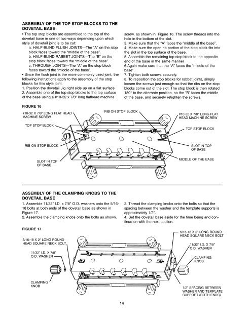
ASSEMBLY OF THE TOP STOP BLOCKS TO THE<br />
DOVETAIL BASE<br />
• The top stop blocks are assembled to the top of the<br />
dovetail base in one of two ways depending upon which<br />
style of dovetail joint is to be cut:<br />
a. HALF-BLIND FLUSH JOINTS—The “A” on the stop<br />
block faces toward the “middle of the base”.<br />
b. HALF-BLIND RABBET JOINTS—The “B” on the<br />
stop block faces toward the “middle of the base”.<br />
c. THROUGH JOINTS—The “A” on the stop block<br />
faces toward the “middle of the base”.<br />
• Since the flush joint is the more commonly used joint, the<br />
following instructions apply to the assembly of the stop<br />
blocks for this style joint.<br />
1. Position the dovetail <strong>Jig</strong> right side up on a flat surface<br />
2. Assemble one of the top stop blocks to the top surface<br />
of the base using a #10-32 x 7/8" long flathead machine<br />
FIGURE 16<br />
#10-32 X 7/8" LONG FLAT HEAD<br />
MACHINE SCREW<br />
TOP STOP BLOCK<br />
RIB ON STOP BLOCK<br />
ASSEMBLY OF THE CLAMPING KNOBS TO THE<br />
DOVETAIL BASE<br />
1. Assemble 11/32" I.D. x 7/8" O.D. washers onto the 5/16-<br />
18 bolts at both ends of the dovetail base as shown in<br />
Figure 17.<br />
2. Assemble the clamping knobs onto the bolts as shown.<br />
FIGURE 17<br />
SLOT IN TOP<br />
OF BASE<br />
5/16-18 X 2" LONG ROUND<br />
HEAD SQUARE NECK BOLT<br />
11/32" I.D. X 7/8"<br />
O.D. WASHER<br />
CLAMPING<br />
KNOB<br />
RIB ON STOP BLOCK<br />
14<br />
screw, as shown in Figure 16. The screw threads into the<br />
hole in the bottom of the slot.<br />
3. Make sure that the “A” faces the “middle of the base”.<br />
4. Make sure the open rib portion of the stop block fits into<br />
the slot in the top surface of the base.<br />
5. Assemble the remaining top stop block to the opposite<br />
end of the base in the same manner<br />
6.Again make sure that the “A” faces the “middle of the<br />
base”.<br />
7. Tighten both screws securely.<br />
8. To reposition the stop blocks for rabbet joints, simply<br />
loosen the screws just enough so that the ribs on the stop<br />
blocks come out of the slot. The stop block is then rotated<br />
180° to the alternate position, so the “B” faces the middle<br />
of the base, and securely retighten the screws.<br />
#10-32 X 7/8" LONG FLAT<br />
HEAD MACHINE SCREW<br />
TOP STOP BLOCK<br />
SLOT IN TOP<br />
OF BASE<br />
MIDDLE OF THE BASE<br />
3. Thread the clamping knobs onto the bolts so that the<br />
spacing between the washer and the template supports is<br />
approximately 1/2".<br />
4. Set the dovetail base aside for the time being and continue<br />
on with the next section.<br />
5/16-18 X 2" LONG ROUND<br />
HEAD SQUARE NECK BOLT<br />
11/32" I.D. X 7/8"<br />
O.D. WASHER<br />
CLAMPING<br />
KNOB<br />
1/2" SPACING BETWEEN<br />
WASHER AND TEMPLATE<br />
SUPPORT (BOTH ENDS)