Industrial Dovetail Jig - Vermont American
Industrial Dovetail Jig - Vermont American
Industrial Dovetail Jig - Vermont American

Create successful ePaper yourself
Turn your PDF publications into a flip-book with our unique Google optimized e-Paper software.
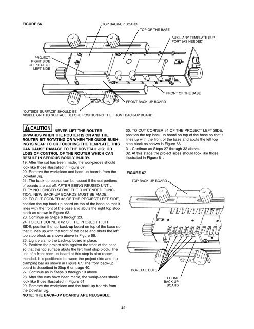
FIGURE 66<br />
PROJECT<br />
RIGHT SIDE<br />
OR PROJECT<br />
LEFT SIDE<br />
TOP BACK-UP BOARD<br />
42<br />
TOP OF THE BASE<br />
FRONT BACK-UP BOARD<br />
“OUTSIDE SURFACE” SHOULD BE<br />
VISIBLE ON THIS SURFACE BEFORE POSITIONING THE FRONT BACK-UP BOARD<br />
CAUTION<br />
NEVER LIFT THE ROUTER<br />
UPWARDS WHEN THE ROUTER IS ON AND THE<br />
ROUTER BIT ROTATING OR WHEN THE GUIDE BUSH-<br />
ING IS NEAR TO OR TOUCHING THE TEMPLATE. THIS<br />
CAN CAUSE DAMAGE TO THE DOVETAIL JIG; OR<br />
LOSS OF CONTROL OF THE ROUTER WHICH CAN<br />
RESULT IN SERIOUS BODILY INJURY.<br />
19. After the cut has been made, the workpieces should<br />
look like those illustrated in Figure 67.<br />
20. Remove the workpiece and back-up boards from the<br />
<strong>Dovetail</strong> <strong>Jig</strong>.<br />
21. The back-up boards can be reused if the cut portions<br />
of boards are cut off. AFTER BEING REUSED UNTIL<br />
THEY NO LONGER SERVE THEIR INTENDED FUNC-<br />
TION, NEW BACK-UP BOARDS MUST BE MADE.<br />
22. TO CUT CORNER #3 OF THE PROJECT LEFT SIDE,<br />
position the top back-up board on top of the base so that it<br />
lines with the front of the base and abuts the right top stop<br />
block as shown in Figure 63.<br />
23. Continue as Steps 6 through 23.<br />
24. TO CUT CORNER #2 OF THE PROJECT RIGHT<br />
SIDE, position the top back-up board on top of the base so<br />
that it lines up with the front of the base and abuts the left<br />
top stop block as shown above in Figure 66.<br />
25. Lightly clamp the back-up board in place.<br />
26. Position the project side against the front of the base<br />
so that the top surface abuts the left front stop block. The<br />
use of a front back-up board at this step is also recommended.<br />
It is positioned between the project side and the<br />
clamping bar as shown in Figure 67. The front back-up<br />
board is described in Step 6 on page 40.<br />
27. Continue as in Steps 8 through 19 above.<br />
28. After the cuts have been made, the workpieces should<br />
look like those illustrated in Figure 61.<br />
29. Remove the workpiece and the back-up boards from<br />
the <strong>Dovetail</strong> <strong>Jig</strong>.<br />
NOTE: THE BACK–UP BOARDS ARE REUSABLE.<br />
FIGURE 67<br />
TOP BACK-UP BOARD<br />
DOVETAIL CUTS<br />
AUXILIARY TEMPLATE SUP-<br />
PORT (AS NEEDED)<br />
FRONT OF THE BASE<br />
30. TO CUT CORNER #4 OF THE PROJECT LEFT SIDE,<br />
position the top back-up board on top of the base so that it<br />
lines up with the front of the base and abuts the left top<br />
stop block as shown is Figure 66.<br />
31. Continue as Steps 27 through 32 above.<br />
32. At this stage the project sides should look like those<br />
illustrated in Figure 61.<br />
FRONT<br />
BACK-UP<br />
BOARD