TM 9-280 1944 Caliber .22 Rifles, All Types - US Army Combined ...
TM 9-280 1944 Caliber .22 Rifles, All Types - US Army Combined ...
TM 9-280 1944 Caliber .22 Rifles, All Types - US Army Combined ...

You also want an ePaper? Increase the reach of your titles
YUMPU automatically turns print PDFs into web optimized ePapers that Google loves.
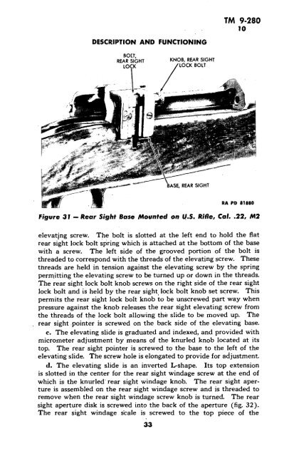
DESCRIPTION AND FUNCTIONING<br />
BOLT,<br />
REAR SIGHT KNOB, REAR SIGHT<br />
LOCK LOCK BOLT<br />
ASE, REAR SIGHT<br />
<strong>TM</strong> 9-<strong>280</strong><br />
10<br />
Figure 31 - Rear Sight Base Mounted on U.S. Rifle, Cal.<strong>.22</strong>, M2<br />
elevating screw. The bolt is slotted at the left end to hold the flat<br />
rear sight lock bolt spring which is attached at the bottom of the base<br />
with a screw. The left side of the grooved portion of the bolt is<br />
threaded to correspond with the threads of the elevating screw. These<br />
threads are held in tension against the elevating screw by the spring<br />
permitting the elevating screw to be turned up or down in the threads.<br />
The rear sight lock bolt knob screws on the right side of the rear sight<br />
lock bolt and is held by the rear sight lock bolt knob set screw. This<br />
permits the rear sight lock bolt knob to be unscrewed part way when<br />
pressure against the knob releases the rear sight elevating screw from<br />
the threads of the lock bolt allowing the slide to be moved up. The<br />
rear sight .pointer is screwed on the back side of the elevating base.<br />
c. The elevating slide is graduated and indexed, and provided with<br />
micrometer adjustment by means of the knurled knob located at its<br />
top. The rear sight pointer is screwed to the base to the left of the<br />
elevating slide. The screw hole is elongated to provide for adjustment.<br />
d. The elevating slide is an inverted L-shape. Its top extension<br />
is slotted in the center for the rear sight windage screw at the end of<br />
which is the knurled' rear sight windage knob. The rear sight aperture<br />
is assembled on the rear sight windage screw and is threaded to<br />
remove when the rear sight windage screw knob is turned. The rear<br />
sight aperture disk is screwed into the back of the aperture (fig. 32).<br />
The rear sight windage scale is screwed to the top piece of the<br />
33