Maxon: OvenPak II: Installation Instructions - Westmill Industries
Maxon: OvenPak II: Installation Instructions - Westmill Industries
Maxon: OvenPak II: Installation Instructions - Westmill Industries

Create successful ePaper yourself
Turn your PDF publications into a flip-book with our unique Google optimized e-Paper software.
Page 2150-S-2<br />
Horizontal mounting is preferred, but burner may<br />
be mounted in any position suitable for automatic<br />
control motor and UV scanner (if used).<br />
OVENPAK ® -<strong>II</strong> Burners will typically be installed<br />
through an oven wall or insulated air duct. Cut opening<br />
approximately 1" larger in diameter than discharge<br />
sleeve to allow for thermal expansion of sleeve.<br />
Burner mounting requires eight studs and a flat<br />
mounting surface perfectly centered on the discharge<br />
sleeve.<br />
After placing burner in position over studs, add lock<br />
washers and nuts, then draw up hand-tight only.<br />
Check that burner is seated evenly all around the<br />
flange, filling any gaps to prevent air leakage, then<br />
tighten all nuts firmly.<br />
For proper performance of any burner, air inlet and<br />
motor should be surrounded by clean, fresh, cool air.<br />
Burner and pipe manifold support will be required<br />
to support weight of the burner and connected pipe<br />
train components. Air control motors, in particular,<br />
require additional support. <strong>Maxon</strong> connecting base and<br />
linkage assemblies are designed to position the control<br />
motors to work with the burner, not to support their<br />
weight.<br />
Suggested supporting arrangements for<br />
OVENPAK ® -<strong>II</strong> Burners<br />
OVENPAK®-<strong>II</strong><br />
Burner<br />
Leg Support<br />
Knee<br />
Bracket<br />
Support<br />
<strong>Installation</strong> <strong>Instructions</strong><br />
Oven<br />
Wall<br />
Burner<br />
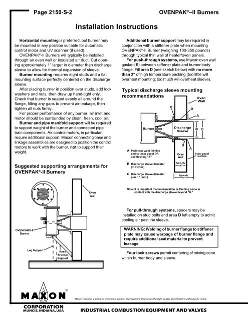
A Perimeter weld thimble<br />
end to inner panel OR<br />
use flashing "A"<br />
B Discharge sleeve diameter<br />
(in inches)<br />
C Discharge sleeve diameter<br />
plus 1" (min.)<br />
OVENPAK ® –<strong>II</strong> Burners<br />
Additional burner support may be required in<br />
conjunction with a stiffener plate when mounting<br />
OVENPAK ® -<strong>II</strong> Burner (weighing 100-350 pounds)<br />
through typical thin wall of heater/oven panels.<br />
For push-through systems, use <strong>Maxon</strong> oven wall<br />
gasket (E) between stiffener plate and burner body<br />
flange. Fill area D (see sketch below) with no more<br />
than 2" of high temperature packing (too little will<br />
overheat mounting; too much will overheat sleeve).<br />
Typical discharge sleeve mounting<br />
recommendations<br />
Discharge<br />
Sleeve<br />
<strong>Maxon</strong> practices a policy of continuous product improvement. It reserves the right to alter specifications without prior notice.<br />
mCORPORATION<br />
MUNCIE, INDIANA, USA INDUSTRIAL COMBUSTION EQUIPMENT AND VALVES<br />
D<br />
Oven<br />
Wall<br />
Typically<br />
4-6"<br />
Typically<br />
8"<br />
A<br />
D<br />
Oven<br />
Wall<br />
B C<br />
Note: It is important that no insulation or flashing come in<br />
contact with the discharge sleeve beyond "D."<br />
E<br />
A<br />
Inner panel<br />
surface<br />
For pull-through systems, spacers may be<br />
installed on stud bolts and area D left empty to admit<br />
cooling air past the sleeve.<br />
WARNING: Welding of burner flange to stiffener<br />
plate may cause warpage of burner flange and<br />
require additional seal material to prevent<br />
leakage.<br />
Four lock screws permit centering of mixing cone<br />
within burner body and sleeve.