Maxon: OvenPak II: Installation Instructions - Westmill Industries
Maxon: OvenPak II: Installation Instructions - Westmill Industries
Maxon: OvenPak II: Installation Instructions - Westmill Industries

Create successful ePaper yourself
Turn your PDF publications into a flip-book with our unique Google optimized e-Paper software.
OVENPAK ® –<strong>II</strong> Burners<br />
General <strong>Instructions</strong><br />
Important: Do not discard packing material until<br />
all loose items are accounted for.<br />
To prevent damage in transit, the spark ignitor,<br />
discharge sleeve, mounting gaskets, flame rod and<br />
connecting linkage components may be packed<br />
separately and shipped loose with your new <strong>Maxon</strong><br />
OVENPAK ® -<strong>II</strong> Burner.<br />
The burner itself is normally only a part of your<br />
complete combustion system. Additional pipe train<br />
accessories and control components will be required<br />
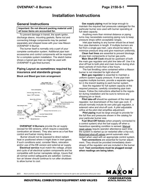
for a complete system installation. The sketch below<br />
shows a typical gas train as might be used with<br />
OVENPAK ® -<strong>II</strong> gas fired burners.<br />
Piping Layout as sometimes required by<br />
insurance and standards groups<br />
Block and Bleed gas train arrangement<br />
OVENPAK ® -<strong>II</strong> Burners provide the air supply<br />
(except for EB versions, which require a separate<br />
combustion air blower). They also serve as a fuel flow<br />
control and fuel/air mixing device.<br />
Burner should not be exposed to direct radiant<br />
heat or positioned where it might draw in inert gases.<br />
If such conditions exist, consider filters, relocation<br />
and/or use of the EB version and external air supply.<br />
Electrical service must match the voltage, phase<br />
and cycle of all electrical system components and be<br />
compatible with burner nameplate ratings. Insure that<br />
all normal control safeguards are satisfied. Combustion<br />
air blower should continue to run after shutdown<br />
to allow burner to cool.<br />
8/01<br />
<strong>Installation</strong> <strong>Instructions</strong><br />
<strong>Maxon</strong> practices a policy of continuous product improvement. It reserves the right to alter specifications without prior notice.<br />
INDUSTRIAL COMBUSTION EQUIPMENT AND VALVES<br />
Page 2150-S-1<br />
Gas supply piping must be large enough to<br />
maintain the required fuel pressures cataloged for the<br />
particular burner size used with burner operating at<br />
full rated capacity.<br />
Anything more than minimal distance or piping<br />
turns may necessitate oversizing piping runs to keep<br />
pressure drops within acceptable ranges.<br />
Inlet pipe leading to any burner should be at least<br />
four pipe diameters in length. If multiple burners are<br />
fed from a single gas train, care should be taken to<br />
minimize pressure drop and give maximum uniformity.<br />
Clean fuel lines are essential to prevent blockage<br />
of pipe train components or burner gas ports.<br />
Main Shut-Off Cock should be upstream of both<br />
the main gas regulator and pilot line take-off. Use it to<br />
shut off fuel to both pilot and main burner during shutdown<br />
periods of more than a few hours.<br />
The fuel throttling valve contained within a <strong>Maxon</strong><br />
burner is not intended for tight shut-off.<br />
Main gas regulator is essential to maintain a<br />
uniform system supply pressure. If one pipe train<br />
supplies multiple burners, provide a separate regulator<br />
in the branch leading to each burner system.<br />
Size the regulator for full system capacity at the<br />
required pressure, carefully considering pipe train<br />
losses. Follow the instructions attached to the regulator<br />
during installation and be sure to remove any<br />
shipping pin or block.<br />
Pilot take-off should be upstream of the main gas<br />
regulator, but downstream of the main gas cock. It<br />
should normally include its own pilot gas regulator, a<br />
solenoid valve and shut-off cock. A pilot adjustable<br />
orifice at the pilot inlet simplifies adjustment.<br />
Pilot piping must be large enough to provide for<br />
the full flow and pressures shown in the catalog for<br />
your particular burner size.<br />
Fuel Shut-Off Valves (when properly connected to<br />
a control system) shut the fuel supply off when a<br />
hazardous operating condition is sensed. Manual<br />
reset valves require operator attendance each time<br />
the system is started up (or restarted after a trip-out).<br />
Motorized shut-off valves permit automatic startrestart<br />
when used with an appropriate control system.<br />
Test connections are essential for burner adjustment.<br />
They should be provided immediately downstream<br />
of the regulator and are included in the burner<br />
itself. Test connections must be plugged except<br />
when readings are being taken.<br />
mCORPORATION<br />
MUNCIE, INDIANA, USA
Page 2150-S-2<br />
Horizontal mounting is preferred, but burner may<br />
be mounted in any position suitable for automatic<br />
control motor and UV scanner (if used).<br />
OVENPAK ® -<strong>II</strong> Burners will typically be installed<br />
through an oven wall or insulated air duct. Cut opening<br />
approximately 1" larger in diameter than discharge<br />
sleeve to allow for thermal expansion of sleeve.<br />
Burner mounting requires eight studs and a flat<br />
mounting surface perfectly centered on the discharge<br />
sleeve.<br />
After placing burner in position over studs, add lock<br />
washers and nuts, then draw up hand-tight only.<br />
Check that burner is seated evenly all around the<br />
flange, filling any gaps to prevent air leakage, then<br />
tighten all nuts firmly.<br />
For proper performance of any burner, air inlet and<br />
motor should be surrounded by clean, fresh, cool air.<br />
Burner and pipe manifold support will be required<br />
to support weight of the burner and connected pipe<br />
train components. Air control motors, in particular,<br />
require additional support. <strong>Maxon</strong> connecting base and<br />
linkage assemblies are designed to position the control<br />
motors to work with the burner, not to support their<br />
weight.<br />
Suggested supporting arrangements for<br />
OVENPAK ® -<strong>II</strong> Burners<br />
OVENPAK®-<strong>II</strong><br />
Burner<br />
Leg Support<br />
Knee<br />
Bracket<br />
Support<br />
<strong>Installation</strong> <strong>Instructions</strong><br />
Oven<br />
Wall<br />
Burner<br />
A Perimeter weld thimble<br />
end to inner panel OR<br />
use flashing "A"<br />
B Discharge sleeve diameter<br />
(in inches)<br />
C Discharge sleeve diameter<br />
plus 1" (min.)<br />
OVENPAK ® –<strong>II</strong> Burners<br />
Additional burner support may be required in<br />
conjunction with a stiffener plate when mounting<br />
OVENPAK ® -<strong>II</strong> Burner (weighing 100-350 pounds)<br />
through typical thin wall of heater/oven panels.<br />
For push-through systems, use <strong>Maxon</strong> oven wall<br />
gasket (E) between stiffener plate and burner body<br />
flange. Fill area D (see sketch below) with no more<br />
than 2" of high temperature packing (too little will<br />
overheat mounting; too much will overheat sleeve).<br />
Typical discharge sleeve mounting<br />
recommendations<br />
Discharge<br />
Sleeve<br />
<strong>Maxon</strong> practices a policy of continuous product improvement. It reserves the right to alter specifications without prior notice.<br />
mCORPORATION<br />
MUNCIE, INDIANA, USA INDUSTRIAL COMBUSTION EQUIPMENT AND VALVES<br />
D<br />
Oven<br />
Wall<br />
Typically<br />
4-6"<br />
Typically<br />
8"<br />
A<br />
D<br />
Oven<br />
Wall<br />
B C<br />
Note: It is important that no insulation or flashing come in<br />
contact with the discharge sleeve beyond "D."<br />
E<br />
A<br />
Inner panel<br />
surface<br />
For pull-through systems, spacers may be<br />
installed on stud bolts and area D left empty to admit<br />
cooling air past the sleeve.<br />
WARNING: Welding of burner flange to stiffener<br />
plate may cause warpage of burner flange and<br />
require additional seal material to prevent<br />
leakage.<br />
Four lock screws permit centering of mixing cone<br />
within burner body and sleeve.
OVENPAK ® –<strong>II</strong> Burners<br />
Discharge sleeve and cone alignment<br />
Cone self centering is achieved by using fixed<br />
length cone screws. This eliminates the need to<br />
adjust for cone alignment. Cone screws should be<br />
tight against the housing to ensure proper cone<br />
spacing and cone security.<br />
CAUTION: Loose cone screws can cause the<br />
following: cone overheating, spark electrode<br />
damage, cone ejection.<br />
The mixing cone is centered in the burner housing<br />
and discharge sleeve to provide a small annular<br />
opening for the flow of cooling air along the discharge<br />
sleeve wall. We SUGGEST periodic inspection of<br />
cone screws for tightness in the housing and from the<br />
discharge side of the burner to insure that annular<br />
opening is maintained.<br />
Blockage of the annular opening will lessen<br />
burner service life.<br />
Discharge sleeve must be flush with, or extend<br />
beyond, interior wall. <strong>Maxon</strong> can supply a special 12"<br />
long discharge sleeve, but higher noise levels may<br />
result, particularly when firing on propane.<br />
An external viewing port should be provided for<br />
flame observation, preferably in such a position that<br />
burner pilot and main flame can both be seen.<br />
4/98<br />
<strong>Installation</strong> <strong>Instructions</strong><br />
<strong>Maxon</strong> practices a policy of continuous product improvement. It reserves the right to alter specifications without prior notice.<br />
INDUSTRIAL COMBUSTION EQUIPMENT AND VALVES<br />
Page 2150-S-3<br />
Flame sensing can be accomplished by either<br />
flame rod or UV scanner. When UV scanner is used,<br />
it should be kept as close to burner as feasible. Heat<br />
block, if used, may affect signal strength with some<br />
brands of scanners.<br />
Field conversion from a flame rod version to a UV<br />
scanner version and vice versa is possible without<br />
any additional burner parts.<br />
Alternate fuels may require correction of supply<br />
pressures.<br />
<strong>Maxon</strong> assumes no responsibility for the use or<br />
misuse of the layouts shown. Specific piping<br />
and wiring diagrams should always be submitted<br />
to the appropriate agencies for approval on<br />
each application.<br />
Multi-burner installations require special considerations<br />
if supplied by a common pipe train and/or air<br />
supply. Air and Gas Balancing Valves should be<br />
used for improved heating uniformity; Gas Swing-<br />
Check Valves should be installed as close as possible<br />
to each burner inlet for dependable lightoff (gas<br />
manifold may otherwise act as a reservoir, preventing<br />
lightoff during trial-for-ignition period).<br />
Control system’s circuitry must not allow main<br />
Fuel Shut-Off Valve to be opened unless combustion<br />
air is on, and must de-energize valve upon loss of<br />
combustion air pressure, along with the other usual<br />
system interlocks. Motor starter is to be interlocked<br />
with valve, whether or not a combustion air pressure<br />
switch is used.<br />
mCORPORATION<br />
MUNCIE, INDIANA, USA
Page 2150-S-4 OVENPAK ® –<strong>II</strong> Burners<br />
<strong>Installation</strong> <strong>Instructions</strong><br />
<strong>Installation</strong> of control motor mounting bracket<br />
Model 425, 435, 445, 487, EB-4, EB-5, EB-6 and<br />
EB-7 OVENPAK ® -<strong>II</strong> Burners require the control motor<br />
mounting bracket to be installed as follows, based on<br />
the type of control motor being used.<br />
To mount the bracket, follow the procedure outlined<br />
below.<br />
1. Determine which holes to use:<br />
– All Barber Coleman control motors use the<br />
holes stamped with the number 2.<br />
– All Honeywell Modutrol control motors use the<br />
holes stamped with the number 3.<br />
Both holes are located on the same side as the<br />
operating shaft elliptical hole. Refer to Figure 2<br />
below.<br />
2. Mount the control motor bracket with two M6X20<br />
hex head screws so the chosen holes align with<br />
the bolt flanges located above the operating shaft.<br />
3. Attach the stand off spacers between the control<br />
motor bracket and the burner with two M6X80 hex<br />
head bolts. Mount the bolts through the narrow<br />
slots located below holes 2 and 3. Refer to Figures<br />
1 and 2.<br />
<strong>Maxon</strong> practices a policy of continuous product improvement. It reserves the right to alter specifications without prior notice.<br />
mCORPORATION<br />
MUNCIE, INDIANA, USA INDUSTRIAL COMBUSTION EQUIPMENT AND VALVES
OVENPAK ® –<strong>II</strong> Burners<br />
Read complete instructions before proceeding,<br />
and familiarize yourself with all the system's equipment<br />
components. Verify that your equipment has<br />
been installed in accordance with the original manufacturer's<br />
current instructions.<br />
CAUTION: Initial adjustment and light-off<br />
should be undertaken only by trained and<br />
experienced personnel familiar with combustion<br />
systems, with control/safety circuitry, and<br />
with knowledge of the overall installation.<br />
<strong>Instructions</strong> provided by the company and/or<br />
individuals responsible for the manufacture<br />
and/or overall installation of complete system<br />
incorporating <strong>Maxon</strong> burners take precedence<br />
over these provided by <strong>Maxon</strong>. If <strong>Maxon</strong><br />
instructions conflict with any codes or regulations,<br />
contact <strong>Maxon</strong> Corporation before<br />
attempting start-up.<br />
For initial OVENPAK ® -<strong>II</strong> Burner start-up:<br />
1. Close all burner fuel valves and cocks. Make<br />
preliminary adjustments to fuel gas regulators.<br />
Remove pilot and main gas regulator’s adjusting<br />
screw covers. Turn adjusting screw down (clockwise)<br />
to approximately mid-position. Close pilot<br />
gas adjustable orifice screw by turning in clockwise<br />
until it stops. (Do not over-tighten.) Then<br />
back out the adjustable orifice (counter-clockwise)<br />
approximately 2-3 turns.<br />
2. Check all electric circuitry. Verify that all control<br />
devices and interlocks are operable and functioning<br />
within their respective settings/ranges. Be<br />
sure all air and gas manifolds are tight and that<br />
test ports are plugged if not being used.<br />
3. Check that all duct and chamber dampers are<br />
properly positioned and locked into operating<br />
positions.<br />
4. Disconnect the automatic control motor’s<br />
coupler from the OVENPAK ® -<strong>II</strong> Burner’s shaft by<br />
loosening the set screw and sliding the coupler<br />
halves apart and removing the rubber coupler.<br />
Make sure that the coupler fingers will rotate<br />
without hitting.<br />
4/98<br />
Start-Up <strong>Instructions</strong><br />
<strong>Maxon</strong> practices a policy of continuous product improvement. It reserves the right to alter specifications without prior notice.<br />
INDUSTRIAL COMBUSTION EQUIPMENT AND VALVES<br />
Page 2150-S-5<br />
For Model EB-MRV Burners, the connecting<br />
linkage on the separate control valve must be<br />
similarly loosened and disconnected. Refer to<br />
specific adjusting procedures relating to control<br />
valve adjustment in <strong>Maxon</strong> catalog.<br />
Initial start-up adjustment should only be<br />
accomplished during a manual burner control<br />
mode.<br />
5. Start all system-related fans and blowers.<br />
Check for proper motor rotation and impeller<br />
direction. Verify that all control interlocks are<br />
working. Allow air handling equipment to run for<br />
adequate purge of your manifolds and combustion<br />
chamber plenums. With main gas shut off,<br />
manually advance burner to high fire position so<br />
that air only flows through burner and combustion<br />
chamber.<br />
CAUTION: Do not by-pass control panel timers<br />
typically controlling sequential operations.<br />
For EB OVENPAK ® -<strong>II</strong> Burners only (step 6)<br />
6. Verify differential air pressure. With combustion<br />
air blower on, all volume air fans operating, and<br />
burner at high fire position, connect a manometer<br />
between the air test connection on backplate of<br />
OVENPAK ® -<strong>II</strong> Burner and your combustion<br />
chamber static pressure test connection. This will<br />
give a direct differential air pressure reading.<br />
mCORPORATION<br />
MUNCIE, INDIANA, USA
Page 2150-S-6<br />
Determine your differential air pressure reading<br />
by taking an additional reading with manometer<br />
connected between the burner's air pressure test<br />
port and atmosphere with the burner at high fire<br />
position, fuel valves closed, and all air handling<br />
systems running. Subtract the combustion<br />
chamber static pressure obtained above from this<br />
air pressure reading to give you differential air<br />
pressure reading. The differential air pressure<br />
setting determines the burner’s capacity and<br />
performance capabilities.<br />
7. Determine the required differential gas pressure<br />
using this differential air pressure reading<br />
obtained from step 6. If your combustion chamber<br />
does not have a static pressure test connection,<br />
then you must measure combustion chamber<br />
static pressure by connecting a manometer<br />
between the gas pressure test port on the<br />
burner’s backplate and to atmosphere with the<br />
burner at low fire position, fuel valves closed, and<br />
all air handling systems running. High fire pressures<br />
are provided in <strong>Maxon</strong> product line catalog<br />
literature and/or read data stamped into burner<br />
nameplate.<br />
8. Verify that spark ignitor is properly positioned<br />
and lines up with the appropriate dimensions<br />
required for your specific burner. (Refer to appropriate<br />
<strong>Maxon</strong> catalog specification table.) Check<br />
that spark ignitor arcs at the end of your properly<br />
positioned ignitor.<br />
9. Return burner control valve (or crank) to low<br />
fire position when purge of system is complete.<br />
10. Open main and pilot gas cocks, then attempt<br />
spark ignition to light pilot while slowly turning<br />
pilot gas regulator spring clockwise and/or<br />
adjustable orifice screw counter-clockwise to<br />
increase fuel flow. Repeat procedure as necessary<br />
until pilot ignites as air might have to be bled<br />
out of fuel supply lines before reliable pilot flame<br />
is established. Pilot gas regulator should normally<br />
be set for as low a pressure as possible, using<br />
fuller opening of pilot gas adjustable orifice (if<br />
used).<br />
11. After ignition, adjust pilot flame for good stable<br />
flame shape. A rule of thumb is that any pilot over<br />
a tennis ball size is probably too large. This<br />
assumes you have visual access to the pilot<br />
flame. If this is not possible, then adjust pilot to<br />
give the strongest and most stable flame signal<br />
Start-Up <strong>Instructions</strong><br />
OVENPAK ® –<strong>II</strong> Burners<br />
through your flame safety circuit. This signal<br />
strength can be read with a micro-amp meter. The<br />
signal strength (or range) will be determined by<br />
the specific type of flame safeguard instrument<br />
you have with your burner system.<br />
12. Re-check pilot ignition by closing pilot gas cock<br />
or otherwise causing pilot outage. Re-light and<br />
refine pilot gas adjustment as necessary to get<br />
ignition within a second or two. The flame safeguard<br />
relays should now power your main fuel<br />
Shut-Off Valve(s).<br />
CAUTION: After completing steps above, recheck<br />
all interlocking safety components and<br />
circuitry to prove that they are properly installed,<br />
correctly set, and fully operational. If in<br />
doubt, shut the system down, close pilot cock<br />
and contact responsible individual before<br />
proceeding further.<br />
13. Establish main flame. With burner at low fire<br />
position, back out main gas pressure regulator<br />
adjusting screw (counter-clockwise) to get lowest<br />
outlet pressure possible. Open all manual fuel<br />
shut-off valves (automatic fuel shut-off valve<br />
should already be open) so gas flows to burner<br />
inlet. There should be little, if any, change in<br />
flame appearance. Turn main regulator adjusting<br />
screw in (clockwise) to obtain outlet pressure<br />
of about 4"-6" wc higher than combustion chamber<br />
pressure (2"-4" wc for propane, considerably<br />
higher for some EB versions). Main flame should<br />
now appear larger than pilot-only flame.<br />
14. Establish high fire setting by slowly moving<br />
burner toward high fire position while observing<br />
gas pressure at burner gas test connection.<br />
Refine main gas regulator adjustment as necessary<br />
to provide correct differential pressure<br />
(gauge to combustion chamber, see step 7) at<br />
high fire. If pressure cannot be adjusted low<br />
enough, a different regulator or regulator spring<br />
may be necessary, or a limiting orifice valve (such<br />
as <strong>Maxon</strong>'s Series “BV”) should be added. Do<br />
not, however, exceed 4" wc pressure drop<br />
between regulator outlet and burner inlet.<br />
<strong>Maxon</strong> practices a policy of continuous product improvement. It reserves the right to alter specifications without prior notice.<br />
mCORPORATION<br />
MUNCIE, INDIANA, USA INDUSTRIAL COMBUSTION EQUIPMENT AND VALVES
OVENPAK ® –<strong>II</strong> Burners<br />
CAUTION: If burner(s) go out, close shut-off<br />
valve or shut main gas cock at once. Return to<br />
minimum setting, re-light pilots if necessary,<br />
then turn main gas on again. Check carefully<br />
that every burner is lit before proceeding.<br />
Cycle burner from minimum to maximum<br />
and refine adjustment, if necessary.<br />
For operation with interrupted pilot (as<br />
recommended), shut off pilots and cycle burner<br />
from minimum to maximum and back several<br />
times to verify the flame is maintained.<br />
15. When burner performance is satisfactory and<br />
stable throughout the firing range, reconnect<br />
control motor.<br />
With interrupted pilot, it may be necessary to<br />
set control for somewhat higher than minimum<br />
burner setting to permit hold-in of flame detection<br />
system without pilot.<br />
CAUTION: Internal drive mechanism within the<br />
control motor may be damaged if linkage is<br />
adjusted so as to cause binding with burner in<br />
high or low fire position.<br />
16. Re-check differential gas pressure with unit at<br />
operating temperature. Refine high fire setting if<br />
necessary, considering differential pressure,<br />
flame length, and appearance. Natural gas flame<br />
should normally be predominantly clear blue but<br />
possibly with semi-luminous tips. Dust or contaminants<br />
in the air stream may affect flame appearance.<br />
17. Plug all test connections not in use to avoid<br />
dangerous fuel leakage. Replace equipment<br />
cover caps and tighten linkage screws.<br />
4/98<br />
Start-Up <strong>Instructions</strong><br />
<strong>Maxon</strong> practices a policy of continuous product improvement. It reserves the right to alter specifications without prior notice.<br />
INDUSTRIAL COMBUSTION EQUIPMENT AND VALVES<br />
Page 2150-S-7<br />
18. Check out overall system operation by cycling<br />
through light-off at minimum, interrupting pilot,<br />
and allowing temperature control system to cycle<br />
burner from minimum to maximum and return.<br />
Recheck all safety system interlocks for proper<br />
setting and operation.<br />
NOTE: Typical gas firing control sequence for <strong>Maxon</strong><br />
burner is provided only as a guide. <strong>Instructions</strong><br />
provided by complete system manufacturer incorporating<br />
<strong>Maxon</strong> burners take precedence.<br />
For gas firing OVENPAK ® -<strong>II</strong> Burner<br />
Light-off: Shut-down:<br />
1. Close cocks, shut-off valve(s) 1. Close main &<br />
2. Verify burner at low fire pilot gas cocks<br />
3. Start recirculating/exhaust fans 2. Keep combustion<br />
4. Start burner blower air blower running<br />
5. Purge at least 4 air changes after shut-down long<br />
6. Open pilot & main gas cocks enough to allow<br />
burner to cool<br />
WARNING: Test every UV installation for<br />
dangerous spark excitation from ignitors and<br />
other possible sources of direct or reflected UV<br />
radiation. Use only gas-tight scanner<br />
connections.<br />
19. Before system is placed into full service,<br />
instruct operator personnel on proper start-up<br />
operation with shut-down of system, establishing<br />
written instructions for their future reference.<br />
mCORPORATION<br />
MUNCIE, INDIANA, USA
Page 2150-S-8 OVENPAK ® –<strong>II</strong> Burners<br />
Notes<br />
<strong>Maxon</strong> practices a policy of continuous product improvement. It reserves the right to alter specifications without prior notice.<br />
mCORPORATION<br />
MUNCIE, INDIANA, USA INDUSTRIAL COMBUSTION EQUIPMENT AND VALVES