Maxon: OvenPak II: Installation Instructions - Westmill Industries
Maxon: OvenPak II: Installation Instructions - Westmill Industries
Maxon: OvenPak II: Installation Instructions - Westmill Industries

You also want an ePaper? Increase the reach of your titles
YUMPU automatically turns print PDFs into web optimized ePapers that Google loves.
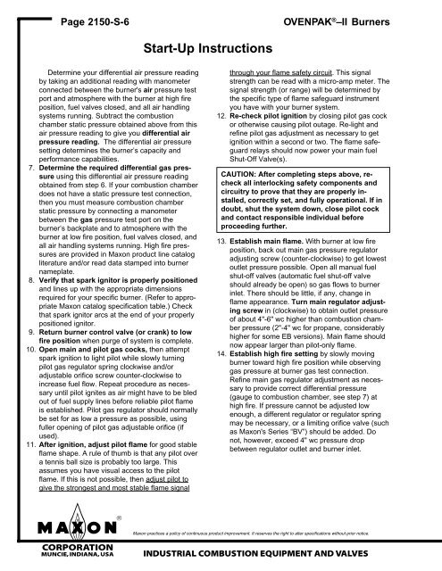
Page 2150-S-6<br />
Determine your differential air pressure reading<br />
by taking an additional reading with manometer<br />
connected between the burner's air pressure test<br />
port and atmosphere with the burner at high fire<br />
position, fuel valves closed, and all air handling<br />
systems running. Subtract the combustion<br />
chamber static pressure obtained above from this<br />
air pressure reading to give you differential air<br />
pressure reading. The differential air pressure<br />
setting determines the burner’s capacity and<br />
performance capabilities.<br />
7. Determine the required differential gas pressure<br />
using this differential air pressure reading<br />
obtained from step 6. If your combustion chamber<br />
does not have a static pressure test connection,<br />
then you must measure combustion chamber<br />
static pressure by connecting a manometer<br />
between the gas pressure test port on the<br />
burner’s backplate and to atmosphere with the<br />
burner at low fire position, fuel valves closed, and<br />
all air handling systems running. High fire pressures<br />
are provided in <strong>Maxon</strong> product line catalog<br />
literature and/or read data stamped into burner<br />
nameplate.<br />
8. Verify that spark ignitor is properly positioned<br />
and lines up with the appropriate dimensions<br />
required for your specific burner. (Refer to appropriate<br />
<strong>Maxon</strong> catalog specification table.) Check<br />
that spark ignitor arcs at the end of your properly<br />
positioned ignitor.<br />
9. Return burner control valve (or crank) to low<br />
fire position when purge of system is complete.<br />
10. Open main and pilot gas cocks, then attempt<br />
spark ignition to light pilot while slowly turning<br />
pilot gas regulator spring clockwise and/or<br />
adjustable orifice screw counter-clockwise to<br />
increase fuel flow. Repeat procedure as necessary<br />
until pilot ignites as air might have to be bled<br />
out of fuel supply lines before reliable pilot flame<br />
is established. Pilot gas regulator should normally<br />
be set for as low a pressure as possible, using<br />
fuller opening of pilot gas adjustable orifice (if<br />
used).<br />
11. After ignition, adjust pilot flame for good stable<br />
flame shape. A rule of thumb is that any pilot over<br />
a tennis ball size is probably too large. This<br />
assumes you have visual access to the pilot<br />
flame. If this is not possible, then adjust pilot to<br />
give the strongest and most stable flame signal<br />
Start-Up <strong>Instructions</strong><br />
OVENPAK ® –<strong>II</strong> Burners<br />
through your flame safety circuit. This signal<br />
strength can be read with a micro-amp meter. The<br />
signal strength (or range) will be determined by<br />
the specific type of flame safeguard instrument<br />
you have with your burner system.<br />
12. Re-check pilot ignition by closing pilot gas cock<br />
or otherwise causing pilot outage. Re-light and<br />
refine pilot gas adjustment as necessary to get<br />
ignition within a second or two. The flame safeguard<br />
relays should now power your main fuel<br />
Shut-Off Valve(s).<br />
CAUTION: After completing steps above, recheck<br />
all interlocking safety components and<br />
circuitry to prove that they are properly installed,<br />
correctly set, and fully operational. If in<br />
doubt, shut the system down, close pilot cock<br />
and contact responsible individual before<br />
proceeding further.<br />
13. Establish main flame. With burner at low fire<br />
position, back out main gas pressure regulator<br />
adjusting screw (counter-clockwise) to get lowest<br />
outlet pressure possible. Open all manual fuel<br />
shut-off valves (automatic fuel shut-off valve<br />
should already be open) so gas flows to burner<br />
inlet. There should be little, if any, change in<br />
flame appearance. Turn main regulator adjusting<br />
screw in (clockwise) to obtain outlet pressure<br />
of about 4"-6" wc higher than combustion chamber<br />
pressure (2"-4" wc for propane, considerably<br />
higher for some EB versions). Main flame should<br />
now appear larger than pilot-only flame.<br />
14. Establish high fire setting by slowly moving<br />
burner toward high fire position while observing<br />
gas pressure at burner gas test connection.<br />
Refine main gas regulator adjustment as necessary<br />
to provide correct differential pressure<br />
(gauge to combustion chamber, see step 7) at<br />
high fire. If pressure cannot be adjusted low<br />
enough, a different regulator or regulator spring<br />
may be necessary, or a limiting orifice valve (such<br />
as <strong>Maxon</strong>'s Series “BV”) should be added. Do<br />
not, however, exceed 4" wc pressure drop<br />
between regulator outlet and burner inlet.<br />
<strong>Maxon</strong> practices a policy of continuous product improvement. It reserves the right to alter specifications without prior notice.<br />
mCORPORATION<br />
MUNCIE, INDIANA, USA INDUSTRIAL COMBUSTION EQUIPMENT AND VALVES