E110 FIREYE FLAME-MONITOR™ - Westmill Industries
E110 FIREYE FLAME-MONITOR™ - Westmill Industries
E110 FIREYE FLAME-MONITOR™ - Westmill Industries

Create successful ePaper yourself
Turn your PDF publications into a flip-book with our unique Google optimized e-Paper software.
DESCRIPTION<br />
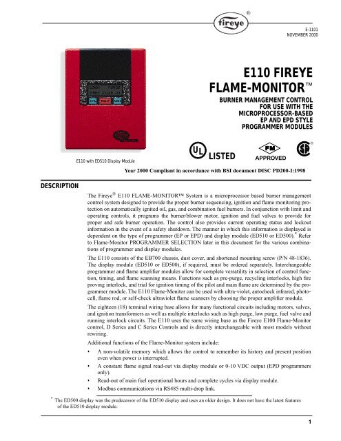
<strong>E110</strong> with ED510 Display Module<br />
The Fireye ® <strong>E110</strong> <strong>FLAME</strong>-MONITOR System is a microprocessor based burner management<br />
control system designed to provide the proper burner sequencing, ignition and flame monitoring protection<br />
on automatically ignited oil, gas, and combination fuel burners. In conjunction with limit and<br />
operating controls, it programs the burner/blower motor, ignition and fuel valves to provide for<br />
proper and safe burner operation. The control also provides current operating status and lockout<br />
information in the event of a safety shutdown. The manner in which this information is displayed is<br />
dependent on the type of programmer (EP or EPD) and display module (ED510 or ED500). * Refer<br />
to Flame-Monitor PROGRAMMER SELECTION later in this document for the various combinations<br />
of programmer and display modules.<br />
The <strong>E110</strong> consists of the EB700 chassis, dust cover, and shortened mounting screw (P/N 48-1836).<br />
The display module (ED510 or ED500), if required, must be ordered separately. Interchangeable<br />
programmer and flame amplifier modules allow for complete versatility in selection of control function,<br />
timing, and flame scanning means. Functions such as pre-purge, recycling interlocks, high fire<br />
proving interlock, and trial for ignition timing of the pilot and main flame are determined by the programmer<br />
module. The <strong>E110</strong> Flame-Monitor can be used with ultra-violet, autocheck infrared, photocell,<br />
flame rod, or self-check ultraviolet flame scanners by choosing the proper amplifier module.<br />
The eighteen (18) terminal wiring base allows for many functional circuits including motors, valves,<br />
and ignition transformers as well as multiple interlocks such as high purge, low purge, fuel valve and<br />
running interlock circuits. The <strong>E110</strong> uses the same wiring base as the Fireye E100 Flame-Monitor<br />
control, D Series and C Series Controls and is directly interchangeable with most models without<br />
rewiring.<br />
Additional functions of the Flame-Monitor system include:<br />
• A non-volatile memory which allows the control to remember its history and present position<br />
even when power is interrupted.<br />
• A constant flame signal read-out via display module or 0-10 VDC output (EPD programmers<br />
only).<br />
• Read-out of main fuel operational hours and complete cycles via display module.<br />
• Modbus communications via RS485 multi-drop link.<br />
* The ED500 display was the predecessor of the ED510 display and uses an older design. It does not have the latest features<br />
of the ED510 display module.<br />
UL ®<br />
®<br />
E-1101<br />
NOVEMBER 2000<br />
<strong>E110</strong> <strong>FIREYE</strong><br />
<strong>FLAME</strong>-MONITOR <br />
BURNER MANAGEMENT CONTROL<br />
FOR USE WITH THE<br />
MICROPROCESSOR-BASED<br />
EP AND EPD STYLE<br />
PROGRAMMER MODULES<br />
LISTED<br />
APPROVED<br />
Year 2000 Compliant in accordance with BSI document DISC PD200-I:1998<br />
®<br />
1
2<br />
• Dipswitches located on the EP programmer to allow selectable purge time.<br />
• A run/check switch which allows the operator to stop the program sequence in any of three different<br />
positions (Purge, PTFI, or Auto).<br />
•<br />
Remote Display Capability.<br />
CAUTION: While programmers are mechanically interchangeable in that they mate with a<br />
common wiring base, you should select the correct model for your application. Inappropriate<br />
application of a control could result in an unsafe condition hazardous to life and property.<br />
Selection of a control for a particular application should be made by a competent professional,<br />
such as a boiler/burner service technician licensed by a state or other government<br />
agency.<br />
<strong>FLAME</strong>-MONITOR SPECIFICATIONS<br />
Supply Voltage: 120 VAC (+10%, -15%) 50/60 Hz<br />
Power Consumption: 25 VA<br />
Shipping Weight: (<strong>E110</strong> Approx.) 5 lbs. (2.3kg)<br />
Operating Temperature Limits:<br />
With ED500 Display: - 40°<br />
F Minimum, +125°<br />
F Maximum<br />
- 40°<br />
C Minimum, +52°<br />
C Maximum<br />
With ED510 Display: 32°<br />
F minimum, +125°<br />
F Maximum<br />
0°<br />
C Minimum, +52°<br />
C Maximum<br />
Humidity: 85% R.H. Maximum (Non-condensing)<br />
AMBIENT TEMPERATURE LIMITS<br />
®<br />
MAXIMUM MINIMUM<br />
CONTROL 140°F 60°C - 40°F - 40°C<br />
Scanner UV1A, UV2,<br />
UV8A, 45UV3<br />
200°F 93°C - 40°F - 40°C<br />
45UV5-1007, 45UV5-<br />
1009<br />
200°F 93°C - 40°F - 40°C<br />
Photocell 45CM1 165°F 74°C - 40°F - 40°C<br />
Flame Rod<br />
(Tip 2460 F)<br />
1500°F 816°C - 40°F - 40°C<br />
48PT2 125°F 52°C - 40°F - 40°C
ELECTRICAL RATINGS<br />
APPROVALS<br />
LOAD RATINGS<br />
TERMINAL TYPICAL LOAD A. Maximum Rating @120V-50/60Hz B. Alternate Rating @120-50/60Hz<br />
5, 6 Individually or<br />
Combined<br />
Pilot Valve(s) and Ignition<br />
Transformer(s)<br />
50VA Pilot Duty (Solenoid Valves)<br />
plus 500VA (Transformer)<br />
Maximum Simultaneous Connected Load: 2000 VA<br />
VA ratings (not specified as pilot duty) permit the connection of transformers and similar devices<br />
whose inrush current is approximately the same as their running current.<br />
VA Pilot Duty ratings permit the connection of relays, solenoid valves, lamps, etc. whose total operating<br />
load does not exceed the published rating and whose total inrush current does not exceed 10<br />
times the rating.<br />
Running and locked rotor ratings are intended for motors. VA and VA Pilot Duty loads may be<br />
added to a motor load provided the total load does not exceed the published rating.<br />
WARNING: This equipment is a Class B digital apparatus which complies with the Radio<br />
Interference Regulations, CRC c.1374.<br />
CAUTION: Published load ratings assume that no contact be required to handle inrush current<br />
more often than once in 15 seconds. The use of control switches, solenoid, relays, etc.<br />
which chatter will lead to premature failure. It is important to run through a test operation<br />
(with fuel shut off) following the tripping of a circuit breaker, a blown fuse, or any known<br />
instance of chattering of any external current consuming devices.<br />
Underwriters Laboratories Inc.: Listed Guide MCCZ File MP1537<br />
Canadian Standards Association: File #LR7989<br />
Acceptable by: Industrial Risk Insurers (I.R.I.)<br />
Factory Mutual Approved<br />
Year 2000 Compliant in accordance with BSI document DISC PD2000-I:1998<br />
WARNING: This equipment generates and can radiate radio frequency energy, and if not<br />
installed and used in accordance with the instruction manual may cause interference to radio<br />
communications. It has been tested and found to comply with the limits for a Class A computing<br />
device pursuant to Subpart J of part 15 of FCC Rules, which are designed to provide reasonable<br />
protection against such interference when operated in a commercial environment.<br />
Operation of this equipment in a residential area is likely to cause interference in which case<br />
the user, at his own expense, will be required to take whatever measures which may be<br />
required to correct the interference.<br />
®<br />
125VA Pilot Duty Solenoid Valves plus<br />
250VA (Transformer)<br />
7 Main Fuel Valve(s) 250VA Pilot Duty (Solenoid Valve) 1250 VA Opening 500 VA Holding<br />
(Motorized Valve) plus 65 VA Pilot Duty<br />
(Solenoid Valve)<br />
M Burner/Blower Motor 9.8 F.L.A. * 58.8 L.R.A. 240 VA Pilot Duty (Motor Starter Coil)<br />
10-11-12-X Modulator 125 Pilot Duty<br />
A Alarm 50 VA Pilot Duty<br />
Terminal ratings may be selected from either column A or B: (select the rating from the column for each terminal which best applies to<br />
the connected load on that terminal).<br />
* F.L.A. = full load amps L.R.A. = locked rotor amps<br />
3
<strong>FLAME</strong> AMPLIFIER SELECTION<br />
SCANNER SELECTION<br />
<strong>FIREYE</strong>®<br />
<strong>FLAME</strong>-MONITOR Selection Guide<br />
4<br />
1.<br />
2.<br />
<strong>FIREYE</strong> P/N DESCRIPTION USE WITH SCANNER<br />
EUV1 Standard UV Amplifier UV1A, UV8A 45UV3, UV2<br />
E1R1 Autocheck Infrared Amplifier 48PT2<br />
E1R2 Autocheck Infrared Amplifier (For special applications -<br />
high sensitivity—consult factory)<br />
48PT2<br />
E1R3 Autocheck Infrared Amplifier. (Without oil fog rejection<br />
spray circuitry.)<br />
48PT2<br />
ERT1 Rectification Amplifier 45CM1, 69ND1<br />
EUVS4 Self-Check UV Amplifier 45UV5-1007/1008/1009<br />
<strong>FIREYE</strong> P/N DESCRIPTION USE WITH<br />
SCANNER<br />
48PT2-1003<br />
48PT2-9003<br />
48PT2-1007<br />
48PT2-9007<br />
UV1A3<br />
UV1A6<br />
UV8A<br />
UV2<br />
45UV3-1050<br />
45CM1-1000<br />
45CM1-1000Y<br />
69ND1-1000K4<br />
69ND1-1000K6<br />
69ND1-1000K8<br />
45UV5-1007<br />
45UV5-1008<br />
45UV5-1009<br />
Infrared 1/2" straight mount 96" cable<br />
Infrared 1/2" 90°<br />
angle mount 96" cable<br />
Infrared 1/2" straight mount 48" cable<br />
Infrared 1/2" 90°<br />
angle mount 48" cable<br />
UV 1/2" straight 36" flex conduit<br />
UV 1/2" straight 72" flex conduit<br />
UV 1/2" 90°<br />
head 72" unshielded leads<br />
UV 3/8" straight 36" flex conduit<br />
UV 3/4" cast aluminum housing 8' cable<br />
Photocell Scanner with filter<br />
Photocell Scanner without filter<br />
Flame rod 12", 1/<br />
2"<br />
N.P.T. mount<br />
Flame rod 18", 1/<br />
2"<br />
N.P.T. mount<br />
Flame rod 24", 1<br />
/ 2"<br />
N.P.T. mount<br />
Self-check UV 1" British thread mounts, 230V<br />
Self-check UV 1" British thread mounts, 120V<br />
Self-check UV 1" N.P.T. threads, 120V<br />
SELECT CHASSIS<br />
<strong>E110</strong> <strong>FLAME</strong>-MONITOR<br />
SELECT PROGRAMMER<br />
EP Programmers provide selectable operation (e.g. extended purge time)<br />
EPD programmers have integral LED indicator display<br />
®<br />
E1R1, E1R2,<br />
or E1R3<br />
BULLETIN<br />
SC-103<br />
EUV1 SC-102<br />
ERT1 SC-103<br />
EUVS4 SC-101<br />
Non-Recycle Operation Recycle Operation Description Non-Modulation Description<br />
EP160 EPD160 EP260 EPD260 10 and 15 sec. TFI EP380 EPD380 30 sec. purge<br />
EP161 EPD161 EP261 EPD261 Extended MTFI EP381 EPD381 15 sec. purge<br />
EP165 EPD165 EP265 EPD265 Pilot stabilization EP382 EPD382 1 sec. purge<br />
EP166<br />
Pilot stabilization<br />
EP170 EPD170 EP270 EPD270 Early spark termination EP390 EP390 90 sec. purge<br />
NOTE: The EP programmers listed above are available in both Spanish and French languages.<br />
Consult factory or your local Fireye distributor for ordering information.
3. SELECT DISPLAY Required for EP Programmers, Optional for EPD programmers<br />
ED510 2 line x 16 character LCD display.<br />
4. SELECT AMPLIFIER Requires appropriate flame scanner.<br />
5. SELECT WIRING BASE<br />
60-1386-2 Surface mount<br />
60-1466-2 Panel mount<br />
6. SELECT ACCESSORIES<br />
Description Use with scanner<br />
EUV1 Standard ultra-violet amplifier UV1A, UV2, UV8A, 45UV3<br />
EUVS4 Self-check ultra-violet amplifier 45UV5-1007, 1008, 1009<br />
E1R1 Autocheck infra-red amplifier 48PT2<br />
E1R2 Autocheck infrared amplifier (with high sensitivity circuitry) 48PT2<br />
E1R3 Autocheck infrared amplifier (without oil fog rejection circuitry) 48PT2<br />
ERT1 Flame rectification amplifier 69ND1, 45CM1<br />
<strong>FIREYE</strong> P/N DESCRIPTION BULLETIN<br />
ED510 Display Module (2 line x 16 characters LCD Display) ED5101<br />
129-145-1, -2, -3 Remote Display Mounting Kit (for ED510) with 4’, 8’ or 2’ cable respectively E-8002<br />
ED500 Display Module (8 character LED Display) E-8101<br />
ED400 Remote display mounting kit (for ED500) E-8001<br />
ED550 Remote display cables (for ED500) E-8001<br />
E300 Expansion Module E-3001<br />
E350-3, -6 Expansion Module cables in 3’ and 6’ lengths E-3001<br />
ED150-3, -6, -15, -25 Remote Reset cables in 3’, 6’, 15’ and 25’ lengths E-8001<br />
ED600 Multi-port Cable Adapter E-8001<br />
ED610 Multi-port Adapter (for ED510 and RS485 communications) E-8002<br />
E500-3 Communication Interface (up to 6 Flame-Monitor controls) E-5001<br />
E700 Software Program to Monitor E500 Operation. IBM Compatible E-7001<br />
60-2333 Noise Line Filter E-1021<br />
EC485 RS232 to RS485 converter for direct connect EC-4851<br />
ED512-2, -4, -8 Communications interface cables in 2’, 4’ and 8’ lengths E-8002<br />
ED580-2, -4, -8 Remote display cables in 2’, 4’ and 8’ lengths E-8002<br />
®<br />
5
<strong>FLAME</strong>-MONITOR Ordering Information<br />
6<br />
<strong>E110</strong> Flame-Monitor (One required) ED510 Display Module<br />
<strong>E110</strong> consists of:<br />
EB700 Chassis<br />
EC600 Dust Cover<br />
Mounting Screw (48-1836)<br />
®<br />
Required with EP Programmers<br />
Optional with EPD Programmers<br />
Amplifier Module (One Required) Wiring Base (One Required)<br />
E1R1<br />
E1R2<br />
E1R3<br />
EUV1<br />
EUVS4<br />
ERT1<br />
EP Programmer<br />
EP(D)160<br />
EP161<br />
EP165<br />
EP(D)166<br />
EP(D)170<br />
EP260<br />
EP261<br />
EP265<br />
EP370<br />
EP380<br />
EP381<br />
EP382<br />
EP390<br />
60-1386-2<br />
Surface Mount<br />
(shown)<br />
60-1466-2<br />
Cabinet Mount<br />
Programmer Module (One Required)<br />
or<br />
EPD Programmer<br />
EPD160<br />
EPD161<br />
EPD165<br />
EPD167<br />
EPD170<br />
EPD260<br />
EPD261<br />
EPD265<br />
EPD270<br />
EPD380<br />
EPD381<br />
EPD382<br />
EPD390<br />
EP programmers must have an Eng. code of 28 or<br />
later (e.g. 9414-28). EPD Programmers must have<br />
an Eng. code of 02 or later.
<strong>FLAME</strong> SCANNERS<br />
45CM1 45UV5-1009 UV8A 45UV3-1050<br />
UV1A 69ND1 48PT2-9000<br />
CAUTION: The UV1, UV2, UV8A and 45UV3 ultra-violet flame scanners and associated<br />
amplifier modules are non-self checking UV systems and should be applied only to burners<br />
that cycle often (e.g.: a minimum of once per 12 hours) in order for the safety checking circuit<br />
to be exercised. If component checking is required during burner operation for constantly<br />
fired burners, utilize the self-checking ultra-violet flame scanners (45UV5) with associated<br />
amplifier module (EUVS4), or the infrared flame scanner (48PT2) with associated Auto<br />
Check amplifier (E1R1, E1R2, E1R3).<br />
<strong>FLAME</strong>-MONITOR PROGRAMMER SELECTION<br />
All programmers for the Flame-Monitor Series are designated with the prefix "EP" or “EPD.” The<br />
functional operation, flame failure response time, purge timings, firing rate motor circuit, trial for<br />
ignition timings, recycling function and display messages are determined by the programmer.<br />
A chart of the most common programmers is found below. Refer to the appropriate product bulletin<br />
for a detailed description of the operation of each programmer.<br />
Take note of the programming sequence chart for each programming module for the proper explanation<br />
of prepurge timings.<br />
WARNING: THE INAPPROPRIATE SELECTION OR APPLICATION OF A PROGRAM-<br />
MER MODULE COULD RESULT IN AN UNSAFE CONDITION HAZARDOUS TO LIFE<br />
AND PROPERTY. The various programmer modules (EP(D)160, EP(D)260 and EP(D)380)<br />
are interchangeable because they plug into a common chassis. Changing the dipswitches<br />
modifies the operation of each programmer module. Care should be taken to insure the<br />
proper dipswitch settings. Refer to the appropriate programmer bulletin for dipswitch settings.<br />
Selection of the programmer module and setting the dipswitches for a particular application<br />
should be made by a competent professional, such as a Boiler/Burner technician<br />
licensed by a state or government agency, engineering personnel of the burner, boiler or furnace<br />
manufacturer (OEM) or in the performance of duties based on the information from the<br />
OEM.<br />
®<br />
7
PROGRAMMER AND DISPLAY MODULE COMPATIBILITY<br />
8<br />
<strong>FIREYE</strong><br />
PART<br />
NUMBER<br />
Pre-purge<br />
programming<br />
(Seconds)<br />
2<br />
EPD/EP PROGRAMMERS<br />
EPD160<br />
EP160<br />
8<br />
EPD167<br />
EPD161<br />
EP161<br />
EPD165,<br />
7<br />
EP165<br />
EPD166,<br />
7<br />
EP166<br />
EPD170<br />
EP170<br />
EPD260<br />
EP260<br />
EPD261<br />
EP261<br />
EPD265<br />
EP265<br />
EPD270<br />
EP270<br />
EPD380<br />
EP380<br />
EPD381<br />
EP381<br />
EPD382<br />
EP382<br />
EPD390<br />
EP390<br />
1<br />
30<br />
Supervised<br />
1<br />
30<br />
Supervised<br />
1 30<br />
Supervised<br />
1 30<br />
Supervised<br />
1<br />
30<br />
Supervised<br />
1<br />
30<br />
1<br />
30<br />
1<br />
30<br />
1<br />
30<br />
30<br />
Proven<br />
High Fire<br />
Purge<br />
Interlock<br />
(D/8 Ckt)<br />
Proven<br />
Low Fire<br />
Start<br />
Interlock<br />
(M/D Ckt)<br />
IntermittentIgnition/Pilot<br />
Interrupted<br />
Ignition/<br />
Pilot<br />
Early Spark<br />
Termination<br />
Yes Yes No Yes No 10<br />
Yes Yes No Yes No 10<br />
Yes Yes No Yes No 10<br />
Yes Yes No Yes No 10<br />
Yes Yes No Yes Yes 5<br />
No Yes No Yes No 10<br />
No Yes No Yes No 10<br />
No Yes No Yes No 10<br />
No Yes No Yes Yes 5<br />
No Yes Yes3<br />
3<br />
15 No Yes Yes<br />
3<br />
0 No Yes Yes<br />
3<br />
90 No Yes Yes<br />
Yes Yes 4<br />
4<br />
Yes Yes<br />
4<br />
Yes Yes<br />
4<br />
Yes Yes<br />
Pilot<br />
Trail-for-Ignition<br />
Term 5 Term 6<br />
All programmers for the Flame-Monitor Series are designated with the prefix “EP” or “EPD.” Two<br />
display modules are functional with the <strong>E110</strong> Flame-Monitor control (ED510 and ED500).The<br />
ED510 is a 2 line by 16 character LCD with keypad to provide both current and historical information<br />
pertaining to the operation of the control. Refer to Bulletin ED-5101 for a complete description<br />
of the features and capabilities of the ED510 display module. The ED500 is an eight character LED<br />
display and was the predecessor to the ED510. The ED500 does not have the latest features of the<br />
ED510 display module. EP style programmers with an Engineering code of 28 or later (e.g. 9414-28)<br />
are compatible with both the ED510 and ED500 display module. EP style programmers with an<br />
Engineering code before 28 are only compatible with the ED500 display. The EPD style programmers<br />
(with an Engineering code 02 or later) are compatible with the ED510 display module as well.<br />
Note: The EPD style programmers do not require a display module to function.<br />
10<br />
10<br />
10<br />
10<br />
10<br />
10<br />
10<br />
10<br />
10<br />
10<br />
10<br />
10<br />
10<br />
10<br />
10<br />
10<br />
10<br />
®<br />
Main<br />
Trail-for-Ignition<br />
10<br />
10<br />
—<br />
—<br />
15<br />
30<br />
6<br />
10<br />
6<br />
15<br />
Running<br />
Interlock<br />
(3/P CKT)<br />
Non Recycle Yes<br />
Non Recycle Yes<br />
Non Recycle Yes<br />
Non Recycle Yes<br />
— Non Recycle Yes<br />
10<br />
10<br />
10<br />
—<br />
—<br />
10<br />
10<br />
10<br />
10<br />
15<br />
30<br />
6<br />
10<br />
10<br />
3<br />
Intermittent<br />
3<br />
Intermittent<br />
3<br />
Intermittent<br />
3<br />
Intermittent<br />
Recycle Yes<br />
Recycle Yes<br />
Recycle Yes<br />
Recycle Yes<br />
Recycle 5<br />
5 Recycle<br />
5 Recycle<br />
5<br />
Recycle<br />
Firing Rate<br />
Motor<br />
Circuit<br />
All programmers have a maximum 4 second Flame Failure Response Time (FFRT) with the exception of the EP165, EP(D)166 and EP265 (2 sec. FFRT).<br />
All EPD Programmers and EP Programmers have selectable 3-P Proven Open to Start feature via dipswitch.<br />
1<br />
These programmers add a 30 second waiting period to the prepurge while the firing rate motor is driven to the low fire position.<br />
2<br />
Purge timings can be extended via dipswitches.<br />
3<br />
EP380, EP381, EP382, and EP390 have selectable intermittent or interrupted (15 sec. MTFI) operation of terminal 6 via dipswitch.<br />
4<br />
These programmers can use terminal “X” for spark termination. This requires jumpering terminals 5 and 10 on the wiring base. PTFI timing is 5 seconds on terminal “X.”<br />
5<br />
EP380, EP381, EP382, and EP390 have selectable Recycle or Non-Recycle Operation via dipswitch.<br />
6<br />
During MTFI terminal 6 is energized for 5 seconds (pilot stabilization) before energizing terminal 7 for 10 seconds for EP165 and EP265 and 15 seconds for EP(D)166 only.<br />
7<br />
EP165 will lockout on power interruption.<br />
8<br />
The EPD167 waits indefinitely for the low fire start switch (M-D) to close.<br />
Term 5<br />
Term 6<br />
None<br />
None<br />
None<br />
None
INSTALLATION OF CONTROL<br />
For a complete system, choose one of each of the following:<br />
- Chassis - Flame Detector<br />
- Programmer Module<br />
- Amplifier Module<br />
- Wiring Base<br />
WARNING: Installer must be trained and qualified. Follow the burner manufacturers instructions,<br />
if supplied. Otherwise, proceed as follows:<br />
Wiring Base<br />
Mount the wiring base on the burner or on a panel. The location should be free from excessive vibration<br />
and within the specifies ambient temperature rating. The base may be mounted in any angular<br />
position.<br />
All wiring should comply with applicable electrical codes, regulations and local ordinances. Use<br />
moisture resistant wire suitable for at least 90 degrees C. Good electrical wiring practice should be<br />
followed to ensure an adequate ground system. Refer to Fireye Service Note 100 separately and<br />
General Grounding Rules, later in this document, for recommended grounding methods<br />
A good ground system should be provided to minimize the effects of AC quality problems. A properly<br />
designed ground system meeting all the safety requirements will ensure that any AC voltage<br />
quality problems, such as spikes, surges and impulses have a low impedance path to ground. A low<br />
impedance path to ground is required to ensure that large currents involved with any surge voltages<br />
will follow the desired path in preferences to alternative paths, where extensive damage may occur to<br />
equipment.<br />
Refer to suggested Wiring Diagram on page 30.<br />
WARNING: Controls require safety limits utilizing isolated mechanical contacts. Electronic<br />
limit switches may cause erratic operation and should be avoided.<br />
BEFORE INSTALLING THE CONTROL<br />
CAUTION: Ensure that electric power is turned off. Refer to SN-100 for recommended<br />
grounding techniques.<br />
If either a ground or a short circuit is detected, it must be eliminated before the control is plugged<br />
into the wiring base and power turned on.<br />
Test the electrical field wiring for short circuits and grounds. The recommended method requires the<br />
use of an ohmmeter set on its lowest resistance scale.<br />
Note: When using ultra-violet or infrared scanning, be sure to remove any jumpers on the wiring<br />
base which ground the S2 terminal.<br />
1. Touch the meter probes together and calibrate accurately to ensure a reliable test.<br />
2. Disconnect the neutral wire (L2) from the control system at the power source. Clip one meter<br />
test lead to the grounded green terminal on the lower right side of the wiring base and with the<br />
other probe touch each other terminal. At no time should the meters show continuity or read 0<br />
ohms.<br />
®<br />
9
INSTALLING THE CONTROL<br />
OPERATION<br />
10<br />
3. Reconnect the neutral wire (L2) at the power source. Remove the test probe from the grounded<br />
terminal and reconnect it to Terminal L2 in the wiring base. With the other probe, touch each<br />
other terminal. It is normal to obtain a resistance reading on the meter at some terminals during<br />
this test as there are resistive loads (coils, transformers, lamps, etc.) connected whose normal<br />
DC resistance may be less than 5 ohms. However, at no time should the test meter read zero<br />
ohms.<br />
CAUTION: Restore power for the following test.<br />
4. With Flame-Monitor removed, measure voltage from L2 to all other terminals. Reading should<br />
be zero on all terminals except Ll.<br />
CAUTION: Electric power must be turned off during installation.<br />
1. Check the electrical tabs on the bottom of the chassis—if they are bent out of position, reposition<br />
them with your fingers so that they are in line as shown here.<br />
2. Select the appropriate programmer and amplifier modules for your application. Remove the dust<br />
cover from the chassis. Insert the amplifier module into the slot marked Flame Amplifier Module<br />
and gently push the module into position. Insert the programmer module into the slot marked<br />
Programmer Module and gently push the module into position. Attach the display to the program<br />
module and plug ED580-1 into RJ45 connections.<br />
3. Slide the slots at the bottom of the assembled control over the tabs on the wiring base. Push the<br />
control into position. Insert a screwdriver through the hole in the top of the control and tighten<br />
the retaining screw.<br />
4. Electric power may now be turned on.<br />
The programmer module determines the functional operation of the <strong>E110</strong> control (e.g. purge timing,<br />
trial for ignition timings, recycle or non-recycle operation, etc.). For purposes of illustration, we will<br />
be looking at the EP160/EPD160 Programmer functions and messages associated with the ED510<br />
display module in this bulletin. Because the messages change depending upon which EP style<br />
programmer is being used, it is necessary to check the bulletin covering the specific programmer<br />
for exact details. Refer to the suggestions shown in this bulletin before proceeding to power the<br />
Fireye <strong>E110</strong> Flame-Monitor system. Items such as scanner installation, short circuit tests and safety<br />
information should be reviewed.<br />
®
T<br />
E<br />
R<br />
M<br />
I<br />
N<br />
A<br />
L<br />
S<br />
TYPE EP(D)160<br />
M<br />
5<br />
6<br />
7<br />
L1/13<br />
ON<br />
NON-RECYCLE RUNNING INTERLOCKS (3/P) PURGE TIME - 30 SEC.*<br />
<strong>FLAME</strong> FAILURE RESPONSE TIME 4 SEC.<br />
PROGRAMMING SEQUENCE<br />
HFS<br />
CLOSED<br />
(D8)<br />
PURGE<br />
30 SEC<br />
MIN<br />
30 SEC<br />
LFS<br />
CLOSED<br />
(MD)<br />
PTFI<br />
10 SEC<br />
MTFI<br />
10 SEC<br />
MTFI<br />
15 SEC<br />
CAUTION: On initial power-up and on restarts following a power failure, the control will<br />
perform self-test diagnostics for 15 seconds.<br />
Start-Up (Normal Cycle)<br />
Note: For direct spark ignited oil burners, substitute the words Main-Oil Valve for Pilot Valve.<br />
1. Constant 120 VAC should be available to the Ll-L2 terminals only on the wiring base.<br />
2. The operating control circuits (Ll-13) will close, signaling the burner to start its firing sequence.<br />
3. If the fuel valve end switch (13-3) is closed, the burner/blower motor (terminal M) circuit is<br />
energized. The running interlock (limit) circuit (3-P) will close (e.g.\ all limits, interlocks, etc.<br />
are proven).<br />
4. The firing rate motor (Modulator Motor) is driven toward the high purge open damper position<br />
(10-X circuit made).<br />
5. When the firing rate motor reaches its open damper position, the Hi Purge switch closes (D-8)<br />
and the prepurge interval of 30*<br />
seconds is initiated. The ED510 will display:<br />
PURGE 0:05<br />
HIGH FIRE PURGE<br />
If the D-8 circuit does not close, the program will hold in this position for ten minutes waiting for it<br />
to close. If it does not, the control will lockout.<br />
6. When the prepurge is completed, the firing rate motor is driven toward the low purge damper<br />
position (10-12 ckt. made). The ED510 will display:<br />
PURGE 0:35<br />
LOW FIRE PURGE<br />
7. Following the minimum 30 second delay (to permit the firing rate motor to get to the low fire<br />
position), the control will wait for the low fire switch (M-D) to close. When it closes, the trial for<br />
ignition sequence will start. If after ten minutes, the M-D circuit is not closed, the control will<br />
lockout. The EPD167 will wait indefinitely for the M-D circuit to close.<br />
*<br />
Prepurge timing is selectable via dipswitches.<br />
FIRING<br />
PERIOD<br />
L1/13<br />
OFF<br />
POST PURGE<br />
15 SEC<br />
(MODULATOR MOTOR CIRCUIT)<br />
HIGH (10-X) LOW (10-12) AUTO (10-11) LOW (10-12)<br />
®<br />
DIPSWITCH SETTINGS<br />
1 2 3 4 5 6<br />
INACTIVE Down Down Down Down<br />
Refer to appropriate programmer<br />
bulletin for a complete description<br />
of the dipswitch functions.<br />
11
BACKLIT DISPLAY<br />
LOCKOUTS<br />
12<br />
8. The trial for ignition period begins with Terminal 5 and 6 being energized simultaneously. This<br />
is known as PTFI (Pilot Trial for Ignition). The ED510 will display:<br />
PTFI 0:02<br />
IGNITION TIMING<br />
This period is ten seconds in duration. If no flame is detected after ten seconds, the control will deenergize<br />
Terminals 5 and 6 and lockout. When flame is detected during this 10 second period, the<br />
ED510 will display<br />
PTFI 20<br />
<strong>FLAME</strong> SIGNAL<br />
9. With flame proven at the end of PTFI, the main flame trial for ignition (MTFI) period begins.<br />
Terminal 7 is energized. The ED510 will display:<br />
MTFI 35<br />
<strong>FLAME</strong> SIGNAL<br />
Terminal 5 is de-energized 10 seconds later and Terminal 6 is de-energized after another 5 seconds.<br />
10. The firing rate motor is now sent to the auto position (10-11 ckt made) and is under the command<br />
of the proportional controller. The ED510 will display:<br />
AUTO 40<br />
<strong>FLAME</strong> SIGNAL<br />
NOTE: Trial-for-Ignition timings depend on the programmer selected. The timing charts on pages 11<br />
and 4 point out the differences in the EP(D)160, EP161, EP165, and EP(D)170.<br />
Normal Shutdown<br />
<strong>FLAME</strong> SIGNAL<br />
0-9<br />
NOT ACCEPTABLE<br />
10<br />
20-80<br />
MINIMUM ACCEPTABLE<br />
NORMAL<br />
1. When the operating control circuit (L1-13) opens, the main fuel valve is de-energized. The firing<br />
rate motor is driven to the low purge position (10-12 ckt mode).<br />
2. Following a 15 second post purge, the burner/blower motor is de-energized.<br />
3. The burner is now off and the ED510 will display<br />
STANDBY<br />
L1-13 OPEN<br />
Burner history can be displayed by using ED510 keypad. See bulletin E-5101.<br />
The ED510 display has a two (2) line by sixteen (16) character backlit LCD display. The backlit<br />
function is energized when power is applied to the <strong>FLAME</strong> MONITOR.<br />
Contrast Control: The contrast for the LCD display is factory set. If the contrast must be adjusted<br />
for any reason (e.g.: remote mounting), a potentiometer is provided on the back of the ED510 display<br />
board. Refer to bulletin ED-5101 for detailed information.<br />
When a safety shutdown occurs, the control will display a message indicating LOCKOUT and the<br />
reason for the lockout. The alarm circuit (Terminal “A”) will be energized. The non-volatile memory<br />
will remember the status of the control even if a power failure occurs. By momentarily depressing<br />
®
the reset button on the display, the control can be reset. The button must be held down for one second<br />
and then released. Very little force is required to do this. Do not press hard.<br />
Safety Shutdown<br />
1. If the running interlock circuit does not close, the control will lockout and the blower motor will<br />
be de-energized. If the interlock circuit opens during a start-up or firing period, all fuel valves<br />
will be de-energized and the control will lockout.<br />
2. If the proven high fire circuit (D-8) has not closed after a ten (10) minute “Hold” period at the<br />
start of prepurge, the control will lockout.<br />
3. If the low fire start circuit (M-D) has not closed after a ten (10) minute “Hold” period at the end<br />
of prepurge, the control will lockout.<br />
4. If dipswitch 6 is in the “Up” position (3-P prove open to start-enabled), and the 3-P circuit is<br />
closed at the start of the operating cycle, the control will hold for one (1) minute waiting for the<br />
3-P circuit to open. If, after one (1) minute, the 3-P circuit does not open, the control will lockout.<br />
5. If pilot flame is not detected during the 10 second trial for ignition period, the pilot valve and<br />
ignition transformer will be de-energized and the control will lockout on safety.<br />
6. If main flame is not detected at the end of the main flame trial for ignition period, all fuel valves<br />
will be de-energized and the control will lockout on safety.<br />
7. If the main flame fails during a firing cycle, all fuel valves will be de-energized within 4 seconds<br />
maximum, after loss of flame signal and the control will lockout on safety.<br />
8. The EP165and EP(D)166 programmers will lockout on a power interruption.<br />
9. If flame is detected when the operating control (L1-13) is open, the control will wait sixty (60)<br />
seconds and then lockout if flame is still present. If the operating control closes and flame is<br />
detected during purge, the blower motor (term M) remains energized and the purge sequence is<br />
put on hold. If the flame signal goes away within sixty (60) seconds, the control will proceed<br />
with a normal start-up. If flame signal is still present after sixty (60) seconds, the control will<br />
lockout.<br />
NOTE: Manual Reset is required following any safety shutdown.<br />
NOTE: Depressing and releasing the reset button during a cycle will cause the control to shut the<br />
burner down and recycle.<br />
DESCRIPTION OF FUNCTIONS OF OPERATING CONTROLS<br />
1. Operating Controls: Generally pressure or temperature activated, the operating control closes,<br />
causing the burner start-up sequence to begin. When the operating control opens, the burner<br />
shuts off. The operating control is connected in the L1-13 circuit on the wiring base.<br />
2. Limit Switches: These are generally pressure, water level or temperature activated<br />
a. Recycle —when it is desired to stop the burner when the limit switch opens and restart it<br />
when the limit switch reclosed, they are connected between Terminals L1 and 13.<br />
b. Non-Recycle —when it is necessary to stop the burner when the limit switch opens and<br />
prevent it from starting until both the limit switch recloses and the manual reset is activated,<br />
they are connected between terminals 3 and P. *<br />
3. Fuel Valve End Switch Interlock: This is generally an integral switch mounted on the main<br />
fuel valve and activated by the valve stem. It is connected between Terminal 3 & 13. The fuel<br />
valve end switch interlock prevents a burner start-up if the valve stem is not in the “valve<br />
closed” position.<br />
* Refer to programmer selection on page 8 to determine which programmers offer non-recycle operation of the running interlock<br />
circuit (ckt. 3-P).<br />
®<br />
13
14<br />
4. Purge Interlock: Generally a firing rate motor linkage position switch or a differential air-pressure<br />
switch, that proves a maximum purge air flow rate. It is connected between Terminals D and<br />
8. The purge interlock proves that the purge air flow rate is at maximum during the purge.<br />
5. Running Interlocks: These generally are air flow switches, high and low fuel pressure switches,<br />
oil temperature switches, atomizing media pressure switches, and excess smoke density controls.<br />
These interlocks prove proper conditions for normal operation of the burner. They are wired in<br />
series and connected between Terminals 3 and P.<br />
6. Low Fire Start Interlock: Generally a firing rate motor linkage position switch or a damper<br />
position switch, will prove both the linkage and dampers are in their proper positions to begin<br />
burner light off. This switch is connected between Terminals M and D.<br />
®
EP(D)160 LOGIC FLOW DIAGRAM NORMAL CYCLE<br />
MODULATOR SENT<br />
TO LOW FIRE<br />
MODULATOR SENT<br />
FROM LOW TO<br />
HIGH FIRE<br />
MODULATOR SENT<br />
FROM HIGH FIRE<br />
TO LOW FIRE<br />
MODULATOR SENT<br />
FROM LOW FIRE<br />
TO AUTO<br />
MODULATOR SENT<br />
FROM AUTO TO<br />
LOW FIRE<br />
MODULATOR HELD<br />
AT LOW FIRE<br />
1<br />
5<br />
6<br />
9<br />
3<br />
7<br />
8<br />
10<br />
11<br />
2<br />
12<br />
13<br />
14<br />
16<br />
17<br />
18<br />
19<br />
4<br />
POWER ON TERMINALS L1 & L2<br />
OPERATING CONTROL CLOSED L1-13<br />
ARE LIMITS L1 TO 13 MADE?<br />
YES<br />
IS F.V.E.S. MADE 13-3<br />
YES<br />
IS AIR FLOW SWITCH MADE? 3-P<br />
YES<br />
IS HIGH FIRE INTERLOCK MADE? D-8<br />
YES<br />
HIGH FIRE PURGE COMPLETED IN 30 SEC.<br />
LOW FIRE PURGE COMPLETED IN 30 SEC.<br />
IS LOW FIRE INTERLOCK MADE? M-D<br />
YES<br />
SPARK & PILOT POWERED ON TERMINALS 5 & 6<br />
IS <strong>FLAME</strong> PROVEN WITHIN 10 SEC?<br />
YES<br />
MAIN FUEL POWERED ON TERMINAL 7 AT END OF PTFI<br />
TERMINAL 5 CUT OUT 10 SEC. AFTER 7 CUT IN<br />
TERMINAL 6 CUT OUT 15 SEC AFTER 7 CUT IN<br />
15 IS <strong>FLAME</strong> PROVED?<br />
YES<br />
TERMINAL 7 REMAINS POWERED<br />
DEMAND SATISFIED L1-13 OPENS<br />
TERMINAL 7 DE-ENERGIZED<br />
BLOWER STOPS 15 SEC. AFTER L1-13 OPENS<br />
+ LOCKOUT AND HOLD MESSAGES ARE EXPLAINED IN THE FOLLOWING PAGES.<br />
NO<br />
NO<br />
NO<br />
NO<br />
NO<br />
NO<br />
®<br />
STANDBY<br />
L1-13 OPEN<br />
NO LOCKOUT +<br />
LOCKOUT +<br />
HOLD 10 MIN. THEN LOCKOUT +<br />
PURGE<br />
HIGH FIRE PURGE<br />
PURGE<br />
LOW FIRE PURGE<br />
HOLD 10 MIN. THEN LOCKOUT +<br />
PTFI<br />
IGNITION TIMING<br />
LOCKOUT +<br />
PTFI<br />
<strong>FLAME</strong> SIGNAL<br />
MTFI<br />
<strong>FLAME</strong> SIGNAL<br />
LOCKOUT +<br />
AUTO<br />
<strong>FLAME</strong> SIGNAL<br />
POST PURGE<br />
CYCLE COMPLETE<br />
STANDBY<br />
L1-13 OPEN<br />
0:05<br />
0:40<br />
0:02<br />
19<br />
35<br />
40<br />
0:05<br />
15
ED510 MESSAGES<br />
16<br />
STANDBY<br />
L1-13 OPEN<br />
RUN MESSAGES<br />
PURGE 0:05<br />
HIGH FIRE PURGE<br />
PURGE 0:35<br />
LOW FIRE PURGE<br />
PTFI 0:02<br />
IGNITION TIMING<br />
PTFI 19<br />
<strong>FLAME</strong> SIGNAL<br />
MTFI 25<br />
<strong>FLAME</strong> SIGNAL<br />
AUTO 40<br />
<strong>FLAME</strong> SIGNAL<br />
POST PURGE 0:05<br />
CYCLE COMPLETE<br />
HOLD MESSAGES<br />
HOLD STANDBY 0:23<br />
3-P INTLK CLOSED<br />
HOLD PURGE 0:00<br />
D-8 LIMIT OPEN<br />
HOLD PURGE 0:00<br />
D-8 LIMIT CLOSED<br />
HOLD PURGE 0:30<br />
M-D LIMIT CLOSED<br />
The operating control of the <strong>FLAME</strong>-MONITOR (terminals L1-13) is open.<br />
Firing rate motor sent to high fire (term. 10-X made), purge timing displayed upper<br />
right hand corner.<br />
Firing rate motor sent to low fire (term. 10-12 made), purge timing displayed in<br />
upper right hand corner.<br />
PTFI timing started. Pilot not proven yet. PTFI timing displayed in upper right<br />
hand corner.<br />
Pilot flame proven during PTFI. Flame signal strength displayed in upper right<br />
hand corner.<br />
Main flame proven during MTFI. Flame signal strength displayed in upper right<br />
hand corner.<br />
Modulator motor sent to auto position (term 10-11 made). Flame signal strength<br />
displayed in upper right hand corner.<br />
Demand satisfied. L1-13 open. Blower motor de-energized 15 seconds after L1-13<br />
opens.<br />
Dipswitch #6 (3-P Proven Open to Start) is set in the Up position (Enabled). At the<br />
start of the cycle, the 3-P circuit was closed. It will hold in this position for 60 seconds<br />
and then lockout if the 3-P circuit does not open.<br />
The control has driven the firing rate motor to high purge (term. 10-X made) and is<br />
waiting for the high fire switch (term. D-8) to close. It will hold this position for<br />
ten (10) minutes and then lockout if the D-8 circuit does not close. Applies to<br />
EP(D)160, EP(D)161, EP165, EP166, EPD167 and EP(D)170 programmers.<br />
Dipswitch #6 (3-P Proven Open to Start) is set in the up position (enabled). At the<br />
start of a cycle the D-8 circuit was closed. It will hold in this position for 30 seconds<br />
and the lockout if the D-8 circuit does not open. Possible solution is to<br />
remove jumper from D-8 circuit or properly set the firing rate motor and switches.<br />
Applies to EP(D)160, EP(D)161, EP165, EP166, EPD167 and EP(D)170 programmers<br />
Dipswitch #6 (3-P Proven Open to Start) is set in the up position (enabled). At the<br />
end of high fire purge and beginning of low fire start, the M-D circuit is closed. It<br />
will hold in this position for 30 seconds and then lockout if the M-D circuit does<br />
not open. The solution is to remove jumper from the M-D circuit or properly set<br />
the firing rate motor and switches. Applies to EP(D)160, EP(D)161, EP165,<br />
EP166, EPD167 and EP(D)170 programmers<br />
®
HOLD PURGE 0:00<br />
M-D LIMIT OPEN<br />
HOLD PURGE 0:10<br />
3-P INTLK OPEN<br />
HOLD STANDBY 25<br />
FALSE <strong>FLAME</strong><br />
LOCKOUT STANDBY<br />
3-P INTLK CLOSED<br />
LOCKOUT PURGE<br />
D-8 LIMIT OPEN<br />
LOCKOUT PURGE<br />
D-8 LIMIT CLOSED<br />
LOCKOUT PURGE<br />
M-D LIMIT CLOSED<br />
LOCKOUT PURGE<br />
3-P INTLK OPEN<br />
LOCKOUT STANDBY<br />
13-3 FUEL VALVE END SWITCH<br />
LOCKOUT PURGE<br />
M-D LIMIT OPEN<br />
LOCKOUT PTFI<br />
3-P INTLK OPEN<br />
LOCKOUT MTFI<br />
3-P INTLK OPEN<br />
LOCKOUT AUTO<br />
3-P INTLK OPEN<br />
LOCKOUT MESSAGES<br />
The control has finished purge and the firing rate motor is driving to the low fire<br />
position (term. 10-12 made) waiting for the low fire start switch (term. M-D) to<br />
close. It will hold this position for ten (10) minutes and then lockout if the M-D<br />
circuit does not close, excluding the EPD167.<br />
The running interlock circuit (3/P) has not closed within the first ten (10) seconds<br />
of purge. The control will hold for ten (10) minutes and then lockout. Applies to<br />
recycle programmers only.<br />
Flame has been sensed during the burner off time (term. L1-13 open) or during the<br />
purge period. This message will hold for sixty (60) seconds and then lockout if<br />
flame is still present. Flame signal strength is displayed in the upper right hand<br />
corner.<br />
Dipswitch #6 (3-P Proven Open to Start) is set in the Up position (Enabled). At the<br />
start of the cycle, the 3-P circuit was closed, and the control has waited 60 seconds<br />
for the 3-P circuit to open.<br />
The control has held for more than 10 minutes waiting for the high fire switch (D-<br />
8) to close. Applies to EP(D)160, EP(D)161, EP165, EP166, EPD167 and<br />
EP(D)170 programmers.<br />
Dipswitch #6 (3-P proven open to start) is set in the up position (enabled). The D-<br />
8 circuit has been closed for 30 seconds at the start of cycle. Applies to EP(D)160,<br />
EP(D)161, EP165, EP166, EPD167 and EP(D)170 programmers<br />
Dipswitch #6 (3-P proven open to start) is set in the up position (enabled).The M-<br />
D circuit has been closed for 30 seconds at the end of high purge or at the beginning<br />
of low fire start. Applies to EP(D)160, EP(D)161, EP165, EP166, EPD167<br />
and EP(D)170 programmers<br />
The running interlock circuit (3-P) has opened during the purge period or failed to<br />
close within the first 10 seconds of purge on non-recycle programmers or has not<br />
closed within 10 minutes on recycle programmers.<br />
The fuel valve end switch wired between terminals 13 and 3 opened during purge<br />
or at start up.<br />
The control has held for more than 10 minutes waiting for the low fire switch (M-<br />
D) to close. This does not apply to the EPD167.<br />
The running interlock circuit (3-P) has opened during the pilot trial for ignition<br />
period. Applies to non-recycle programmers only.<br />
The running interlock circuit (3-P) has opened during the main trial for ignition<br />
period. Applies to non-recycle programmers only.<br />
The running interlock circuit (3-P) has opened during the main burner on period.<br />
Applies to non-recycle programmers only.<br />
®<br />
17
LOCKOUT STANDBY<br />
FALSE <strong>FLAME</strong><br />
LOCKOUT PTFI<br />
<strong>FLAME</strong> FAIL<br />
LOCKOUT MTFI<br />
<strong>FLAME</strong> FAIL<br />
LOCKOUT AUTO<br />
<strong>FLAME</strong> FAIL<br />
LOCKOUT PTFI<br />
SCANNER NOISE<br />
LOCKOUT PURGE<br />
SHORT CIRCUIT TERM 5,6,7<br />
18<br />
LOCKOUT PTFI<br />
FUEL VALVE STATE CHANGE<br />
LOCKOUT AUTO<br />
LINE FREQUENCY NOISE DETECTED<br />
LOCKOUT<br />
AC POWER FAIL<br />
CHECK MESSAGES<br />
CHECK PURGE 0:15<br />
D-8 HI LIMIT<br />
CHECK PURGE 0:45<br />
M-D LOW LIMIT<br />
CHECK PTFI 19<br />
<strong>FLAME</strong> SIGNAL<br />
Flame has been sensed during the burner off time (term. L1-13 open) or during the<br />
purge period for sixty (60) seconds.<br />
A flame failure occurred during the pilot trial for ignition period.<br />
A flame failure occurred during the main trial for ignition period.<br />
A flame failure occurred during the main burner on period.<br />
This message appears because of ignition cable noise. Reroute scanner wires away<br />
from high voltage ignition cables. Check for proper spark gap or cracked porcelain.<br />
Check for proper grounding of wiring base and power supply. Replace worn<br />
ignition cable and/or faulty connections.<br />
Excessive current or short circuit detected on terminals 5, 6, or 7 during PTFI,<br />
MTFI, or Auto. The control will lockout upon sensing this condition on two consecutive<br />
cycles.<br />
During pilot trial for ignition period, voltage sensed on terminal 7 is different from<br />
the previous cycle. (e.g.: jumper added or removed between term. 7 and 5 or 6).<br />
Electrical noise detected on terminals L1 and L2.<br />
A power interruption to terminals L1 and L2 has caused the control to lockout.<br />
Applies to EP165 and EP166 programmers only.<br />
The "Run-Check" switch has been placed in the Check position during purge and<br />
will hold indefinitely. The firing rate motor is being driven to the high purge position.<br />
The "Run-Check" switch has been placed in the Check position after high fire<br />
purge and will hold indefinitely. The firing rate motor is being driven to the low fire<br />
position.<br />
The "Run-Check" switch has been placed in the Check position during the pilot<br />
trial for ignition period. Flame signal strength is displayed in the upper right hand<br />
position. The control will lockout on safety only when no flame signal is sensed for<br />
a continuous 30 seconds while the control is in the Check position.<br />
®
CHECK AUTO 25<br />
LOW FIRE SIGNAL<br />
CHECK STANDBY 00<br />
UNIT ADDRESS<br />
LOCKOUT AUTO<br />
CHECK AMPLIFIER<br />
LOCKOUT PTFI<br />
CHECK CHASSIS<br />
LOCKOUT PURGE<br />
CHECK PROGRAMMER<br />
LOCKOUT AUTO<br />
CHECK SCANNER<br />
LOCKOUT AUTO<br />
CHECK EXPANSION MODULE<br />
LOCKOUT AUTO<br />
AUTO CHECK AMPLIFIER FAIL<br />
<strong>FIREYE</strong> ED510<br />
SYSTEM ERROR<br />
DIAGNOSTIC MESSAGES<br />
The "Run-Check" switch has been placed in the Check position during the main burner on<br />
period. and the firing rate motor is driven to the low fire position. Flame signal strength is<br />
displayed in the upper right hand corner.<br />
The “Check-Run” switch has been placed in the Check position with the operating control<br />
circuit (L1-13) open. Every time the Reset button is depressed and held for one second will<br />
increment the Unit Address by one. Refer to programmer bulletin for additional information<br />
on Unit Address.<br />
POSSIBLE CAUSE SOLUTION<br />
— High electrical noise — Check for proper ground on power supply.<br />
— Install noise suppressor on power supply<br />
(P/N 60-2333).<br />
— Defective field wiring. — Make sure line phase on interlock circuit is<br />
the same as found on L1/L2 power supply to<br />
E100/<strong>E110</strong>.<br />
— Defective amplifier. — Replace amplifier.<br />
— Defective IR scanner. — Replace IR cell.<br />
— Voltage on terminal 7 at<br />
improper time.<br />
— Defective Chassis.<br />
— Defective Programmer.<br />
— Voltage on terminal 5 or 6 at improper<br />
time.<br />
— High Electrical Noise.<br />
— Failed Programmer.<br />
— Worn Chassis.<br />
— Flame signal detected during shutter<br />
close time on 45UV5 scanner.<br />
— The E300 Expansion Module has a<br />
defective optocoupler.<br />
®<br />
— Check wiring to terminal 7.<br />
— Replace Chassis (EB700).<br />
— Replace Programmer.<br />
— Check wiring to terminals 5 and 6.<br />
— Install noise suppressor on power<br />
supply<br />
— Re-route scanner wires away from high<br />
voltage wiring.<br />
— Replace Programmer.<br />
— Replace Chassis.<br />
— Stuck scanner shutter. Replace 45UV5<br />
scanner.<br />
— Replace E300 Expansion Module.<br />
— Amplifier has failed diagnostic checks. — Replace amplifier.<br />
— Defective programmer. — Replace programmer.<br />
19
HISTORICAL INFORMATION /SYSTEM SUB-MENUS<br />
20<br />
AUTO 40<br />
BNR HOURS 823<br />
AUTO 40<br />
BNR CYCLES 385<br />
AUTO 40<br />
BNR LOCKOUTS 21<br />
AUTO 40<br />
SYS HOURS 1233<br />
AUTO 40<br />
LOCKOUT HISTORY<br />
AUTO 40<br />
E300 MSG SELECT<br />
AUTO 40<br />
PROGRAM SETUP<br />
AUTO 40<br />
SYSTEM INFO<br />
At any time the control is powered, the SCRL key will scroll through and display the total number of<br />
burner cycles, burner lockouts, and system hours on the bottom line of the ED510 display. The top<br />
line will continue to show the current run mode of the control (e.g. PURGE, AUTO, etc.). Following<br />
the historical information, the SCRL key will display four (4) System Sub-menus providing the following<br />
information and/or functions:<br />
— Lockout History (with burner cycle and burner hour time stamp).<br />
— E300 Message Select (to program messages associated with the E300 Expansion Module.<br />
— Program Setup (to display programmer type, purge timing, FFRT timing, etc.).<br />
— System Information (status of M-D circuit, average pilot flame signal, etc.).<br />
The system sub-menus require the MODE key to gain access to the information associated with each<br />
sub-menu. An arrow is displayed in the lower right hand corner of the display to indicate a system<br />
sub-menu. Every time the SCRL key is pressed the information is displayed as follows:<br />
* Refer to SYSTEM INFO to reset value to zero.<br />
Number of hours Terminal 7 (main fuel) is energized.*<br />
Number of burner operating cycles. (L1-13 closed).*<br />
Number of burner lockouts.*<br />
Number of hours the control has been powered.*<br />
Sub-menu to display the cause of the last 15 lockouts. The MODE key is required<br />
to display the actual lockouts.<br />
Sub-menu to program the messages associated with the operation of the E300<br />
expansion module. The MODE key is required to enter the sub-menu.<br />
Sub-menu to display various operating parameters of the programmer and amplifier.<br />
The MODE key is required to enter the sub-menu.<br />
Sub-menu to display information pertaining to the operation of the control. The<br />
MODE key is required to enter the sub-menu.<br />
®
LOCKOUT HISTORY<br />
The sub-menu “LOCKOUT HISTORY” will display the last six (6) lockouts, along with the burner<br />
cycle and burner hour when the lockout occurred. When the MODE key is pressed, the screen will display<br />
the most recent lockout condition and the number of that lockout (e.g. LO #127 represents the<br />
127th lockout of that control). The SCRL key will display the Burner Hour, followed by the Burner<br />
Cycle when the lockout occurred. The SCRL key will advance to the next lockout, and repeat the<br />
sequence listed above. The MODE key will exit the sub-menu.<br />
PRESS SCREEN DISPLAYS DESCRIPTION<br />
SCRL AUTO 45<br />
LOCKOUT HISTORY ><br />
MODE LO #158 PURGE<br />
D-8 LIMIT OPEN<br />
SCRL LO #158 PURGE<br />
@ BNR HOURS 136<br />
SCRL LO #158 PURGE<br />
@ BNR CYCLE 744<br />
SCRL LO #157 AUTO<br />
3-P INTLK OPEN<br />
MODE AUTO 45<br />
<strong>FLAME</strong> SIGNAL<br />
Scrolling through the historical information. Control has released to auto<br />
modulation, flame signal strength = 45.<br />
The last (most recent) lockout condition. This is the 158th lockout of the<br />
control.<br />
The last lockout occurred after 136 hours of burner operation.<br />
The last lockout occurred on the 744 burner cycle.<br />
The next to last lockout condition. This is the 157th lockout of the control.<br />
Screen has returned to the run message. Control has released to auto<br />
modulation, flame signal strength = 45.<br />
E300 MESSAGE SELECT<br />
The sub-menu "E300 MSG SELECT" will allow the user to modify the lockout alarm messages associated<br />
with the operation of the E300 Expansion Module. The various safety limits had to be wired in the<br />
exact order that was shown in the E3001 Product Bulletin for the E300. For example, the low water cutoff<br />
had to be wired between terminals 23 and 24 of the 60-1950 wiring base of the E300. With the EP<br />
style programmers (Engineering code 28 or later), the user will now be able to select which message<br />
applies to the individual terminals. The messages associated with the E300 are divided into four (4)<br />
groups: Recycle, Non-recycle, Gas Select, and Oil Select.<br />
The Recycle group pertains to the limits that are connected between terminals L1 and 13 of the E100/<br />
<strong>E110</strong> Flame-Monitor. These are terminals 20-21, 21-22, and 22-13. Note: Refer to Bulletin E-3001 for a<br />
wiring diagram of the E300 terminals.<br />
The Non-Recycle group pertains to limits connected between terminals 3 and P of the E100/<strong>E110</strong><br />
<strong>FLAME</strong>-MONITOR. These are terminals 3-23, 23-24, 30-31, 31-32, 32-33, 33-34, 34-35, and 35-P.<br />
The Gas Select group pertains to the terminals associated with the gas interlocks of the E300. These are<br />
terminals 25-27, 27-30.<br />
The Oil Select group pertains to the terminals associated with the oil interlocks of the E300. These are<br />
terminals 26-28, 28-29, and 29-30.<br />
The lockout messages associated with the above terminals can be modified via the ED510 Display. The<br />
selection of available messages are dependent on each group. For example, the message "Low Oil Pressure"<br />
is a selection only for the Oil Select group. The default message for a particular interlock is the<br />
standard message for those terminals as indicated in the E-3001 bulletin. For example, the default message<br />
for terminals 20-21 is "L1-13 AUX #1 OPEN."<br />
®<br />
21
22<br />
TO MODIFY THE E300 MESSAGES<br />
All three keys: Mode, Reset and Scroll, are used to modify the E300 messages. The Mode key is<br />
used to enter or exit the sub-menu associated with the E300 messages. The Scroll key is used to<br />
advance through the various terminals or selectable messages. The Reset key is used to modify a terminal<br />
message and select a new message. To modify the E300 messages:<br />
Press the Scroll key until the ED510 displays<br />
E300 MSG SELECT.<br />
Press the Mode key and the screen displays:<br />
E300 TERM #20-21<br />
L1-13 AUX#1 OPEN or programmed message.<br />
Press the Scroll key and the screen displays:<br />
E300 TERM #21-22<br />
L1-13 AUX#2 OPEN or programmed message.<br />
To change the message, press and hold the Reset key for one (1) second. When the Reset key is<br />
released, the screen displays:<br />
MDFY TERM #21-22<br />
L1-13 AUX#2 OPEN<br />
Press the Scroll key to display the available messages for the particular group being modified. See<br />
attached List of available messages for each group.<br />
When the messages displayed is appropriate for the terminals, press and hold the Reset key for one<br />
(1) second. When the Reset key is released, the screen displays:<br />
E300 TERM #21-22<br />
LOW WATER or programmed message.<br />
Press the Mode key to exit the E300 Message Sub-menu.<br />
AVAILABLE E300 MESSAGES<br />
The following messages are available for each of the four E300 terminal groups:<br />
GROUP 1 — RECYCLE<br />
E340 OP CNTL OPEN HIGH WATER CONTROL PANEL SWITCH OPEN<br />
DAMPER POSITION END SWITCH OPEN BLOWER MOTOR INTLK HIGH GAS PRESSURE<br />
COMBUSTION AIR END SWITCH OPEN HIGH STACK TEMPERATURE LOW GAS PRESSURE<br />
LOW WATER<br />
GROUP 2 — OIL SELECT<br />
LOW OIL PRESSURE LOW OIL TEMPERATURE LOW ATOMIZING MEDIA<br />
HIGH OIL PRESSURE HIGH OIL TEMPERATURE<br />
GROUP 3 — GAS SELECT<br />
HIGH GAS PRESSURE LOW GAS PRESSURE<br />
GROUP 4 — NON-RECYCLE<br />
E340 SAFETY INTLK OPEN HIGH TEMPERATURE BLOWER MOTOR INTLK<br />
HIGH WATER AIR FLOW OPEN I.D. FAN INTLK<br />
LOW WATER OIL GUN END SWITCH OPEN F.D. FAN INTLK<br />
HIGH PRESSURE HIGH STACK TEMPERATURE<br />
®
USER PROGRAMMED E300 MESSAGES<br />
In addition to selecting the lockout alarm messages for the E300 Expansion Module from a menu<br />
selection via the ED510 display, the user can also program any message (up to 40 characters in<br />
length) for the individual terminals of the E300 using a dumb terminal (or PC with communication<br />
software) and the appropriate interface cables. Refer to bulletin E-3001 for complete details.<br />
PROGRAM SETUP<br />
The sub-menu “PROGRAM SETUP” allows the user to review the various operational settings of<br />
the programmer module (e.g. programmer type, purge timing, etc.). The MODE key is used to enter<br />
the “PROGRAM SETUP” sub-menu, and the SCRL key is used to advance through the sub-menu.<br />
Press Screen Displays Description<br />
SCRL AUTO 45 SCRL key advances through the historical information until<br />
PROGRAM SETUP > “Program Setup” is displayed. Control has released to auto<br />
modulation, flame signal strength = 45.<br />
MODE AUTO 45 Programmer Type is an EP(D)160.<br />
PROGRAMMER EP(D)160<br />
SCRL AUTO 45 Software Engineering code of the programmer module is code 28.<br />
ENGR CODE NO. 28<br />
SCRL AUTO 45 Amplifier module is an EUV1 or an ERT1.<br />
AMP = EUV1 OR ERT1<br />
SCRL AUTO 45 Purge timing (selected by the dipswitches) is 30 seconds.<br />
PURGE TIME 0:30<br />
SCRL AUTO 45 Proven 3-P Open To Start is disabled (selected by dipswitches).<br />
PROVE 3-P OPEN=N<br />
SCRL AUTO 45 Flame Failure Response Time (FFRT) = 4 seconds (maximum).<br />
<strong>FLAME</strong> FAIL TIME 4s<br />
SCRL AUTO 45 Unit Address is 00. Refer to programmer bulletin to modify Unit<br />
UNIT ADDRESS #00 Address.<br />
MODE AUTO 45 MODE key returns to run message.<br />
<strong>FLAME</strong> SIGNAL<br />
®<br />
23
SYSTEM INFO<br />
The sub-menu “SYSTEM INFO” allows the user to review information pertaining to the operation of<br />
the control (e.g. average main flame signal strength, status of the high fire and low fire end switches,<br />
etc.). This information can be very helpful when setting the damper linkages on the firing rate motor.<br />
The MODE key is used to enter the “PROGRAM SETUP” sub-menu, and the SCRL key is used to<br />
advance through the sub-menu.<br />
Press Screen Displays Description<br />
SCRL AUTO 45 SCRL key advances through the historical information until<br />
SYSTEM INFO > “System Info” is displayed. Control has released to auto<br />
modulation, flame signal strength = 45.<br />
MODE AUTO 45 The average flame signal strength of the pilot flame = 22<br />
AVG. PILOT FLM 22<br />
SCRL AUTO 45 The average flame signal strength of the main flame = 40.<br />
AVG. MAIN FLM 40<br />
SCRL AUTO 45 The total number of short circuits (excessive current) detected on<br />
SHORT CKTS. 0 terminals 5, 6, and 7. The short circuit condition must be sensed<br />
twice consecutively to be considered a short circuit.<br />
SCRL AUTO 45 The status of the high fire end switch (D-8) is closed.<br />
D-8 LIMIT CLOSED<br />
SCRL AUTO 45 The status of the low fire end switch (M-D) is closed.<br />
M-D LIMIT CLOSED<br />
SCRL PRESS RESET TO While the control is in STANDBY position (L1-13 OPEN)<br />
CLEAR HISTORY pressing and releasing the RESET key will clear current burner<br />
hours, cycles and lockout history.<br />
MODE AUTO 45 MODE key returns to run message.<br />
24<br />
The EP(D) programmer updates the messages to the ED510 display at least once every 8<br />
seconds. If the ED510 display does not receive information from the EP(D) programmer<br />
within 10 seconds the ED510 will display:<br />
<strong>FIREYE</strong> ED510<br />
WAITING FOR DATA<br />
This can be the result of a defective connection between the programmer and display,<br />
defective cable, defective drivers in the programmer or display, or an electrical noise transient<br />
causing the EP(D) programmer to cease communication.<br />
Removing and restoring power should be executed to recover proper operation. Refer to<br />
bulletin SN-100 for recommended techniques for display installation.<br />
®
COMMUNICATIONS<br />
The protocol to be used is Modbus RTU. This is implemented by the master (PC, PLC, etc.) issuing<br />
a poll to the slave (Flame-Monitor) and the slave responding with the appropriate message.<br />
A typical format of a poll request is as follows:<br />
DST FNC ADR<br />
HI<br />
ADR<br />
LO<br />
DAT<br />
HI<br />
DST refers to the logical address of the slave.<br />
FNC is the function being requested. FNC 03 is a read request.<br />
ADR is the message number or register number of the data being requested. In Modbus, register<br />
addresses begin at 40001 but is interpreted as address 00.<br />
DAT is the number of words being requested. A word is an integer consisting of 2 bytes.<br />
The normal response from a slave is as follows:<br />
DST FNC DBC DATA….<br />
Hi/Lo<br />
DBC is the data byte count being returned. It must be two times the DAT number from the poll<br />
request.<br />
DATA is the data returned and is always a series of 2 byte integers. If 4 words were requested then<br />
DBC would be 8 and there would be 8 data bytes or 4 data words containing the requested data.<br />
The format of the data is 4800,N,8,1 meaning 4800 baud, no parity, and 1 stop bit.<br />
Below is a table of currently available messages provided by the Flame-Monitor programmers, followed<br />
by a description where necessary, EP engineering code 38 or greater and EPD engineering<br />
code 4 or greater.<br />
DAT<br />
LO<br />
CRC<br />
LO<br />
®<br />
CRC<br />
LO<br />
MESSAGE WORD<br />
RESPONSE VALUE<br />
ADDRESS REQUESTED<br />
00 1-6 STATUS 83 (053H) = RUN;<br />
202 (0CAH) = LOCKOUT<br />
01 1 MSGN Current message being displayed<br />
(see Table 1)<br />
02 1 GSTAT Defines Timer Type<br />
03 1 TIMER Time, Flame, Address<br />
04 1 <strong>FLAME</strong> Flame Signal<br />
05 1-3 LOGSTAT Current logic module, PURGE,<br />
PTFI, AUTO (See Table 2)<br />
06 1 INPUTS Input limits state<br />
07 1 OUTPUTS Output relays state<br />
08 2 SYSMINS System on minutes<br />
10 2 BNRMINS Burner on minutes<br />
12 2 CYCLES Completed Burner Cycles<br />
14 1 LOCKOUT COUNT Stored Lockout Count<br />
15 1-6 LOCKOUT HISTORY Last 6 Lockouts, first word is<br />
most current lockout<br />
21 1-2 DEVTYP Programmer device type, 5=EP,<br />
6=EPD, 7=MicroM<br />
22 1 AMPTYP Amplifier Type; EUVS4=0C0H;<br />
EIR1=0A0H;<br />
ERT1, EUV1=090H;<br />
CRC<br />
HI<br />
CRC<br />
HI<br />
25
26<br />
Message 00 and message 05 are unique in that a limited number of successive registers can be combined<br />
with these requests. For example, a request to message 00 can contain up to 6 data words. The<br />
response to this would contain STATUS, MSGN, GSTAT, TIMER, <strong>FLAME</strong> and LOGSTAT. If the<br />
requested data word count (DAT) were to be 2 then the response would contain STATUS and MSGN<br />
only.<br />
The MSGN being transmitted is a numerical value and must be interpreted by the communicating<br />
device, which actually is an advantage since this can be made to be whatever message text the end<br />
user wants. In other words, it allows for programming custom messages without actually changing<br />
the message in the programmer. Refer to the message table for a complete description.<br />
The Flame-Monitor stores its burner on time and system on time (L1 powered) in minutes. The programmer<br />
normally converts this to hours for display purposes. The information being supplied by<br />
Modbus will be the actual time in minutes and it is up to the communicating device to do the conversion.<br />
Since the maximum value stored in the Flame-Monitor is 9,999,999 minutes, the maximum<br />
value in hex therefore is 98967FH and comprises two data words. The maximum cycle count is<br />
999,999 decimal or F423FH, still two data words.<br />
All values are represented in a HEX or base 16 format.<br />
GSTAT determines the type of value TIMER represents. TIMER can be a running timer such as is<br />
used in purge, a flame signal or meaningless. Only the lower nibble of GSTAT has any value. If this<br />
value is 0 then the TIMER value has no meaning. The value in TIMER is a background minute timer<br />
in the Flame-Monitor and should be ignored. If GSTAT is between 4 and 7, the TIMER represents<br />
the current value flame signal. If GSTAT is a 1, 2, or 3 then TIMER represents a running timer value.<br />
The baud rate of the Flame-Monitor is fixed at 4800 bits per second. The format of the data is 8 data<br />
bits, no parity and 1 stop bit. Due to the RS485 format, the communication format is considered halfduplex.<br />
That is, only one user is permitted on the communication lines at a time.<br />
The information contained in INPUTS and OUTPUTS represents the status of the interlocks and<br />
relays respectively. For the INPUTS, a 1 in the interlock position defines the interlock as being on or<br />
energize where the 1 in any bit position in the OUTPUT register signifies the relay as being energized.<br />
Term P<br />
INPUTS<br />
Term 5/6 Term D Term 8 Term 7 Term 3 Term 13<br />
Air Flow Ignition Low Fire Ref High Fire Main Fuel FVES or<br />
POC<br />
Op Ctrl<br />
A ‘1’ in the opto-coupler position indicates the opto-coupler is on or interlock closed.<br />
OUTPUTS<br />
Term 11 Term M Term 6 Term 5 Term 7 Term A Term X<br />
Auto (RA1) Blower (RB) Ignition FVES (RV) Pilot Main Fuel Alarm (RL) High Fire<br />
(RA2)<br />
(RP) (RF)<br />
(RH)<br />
LOGSTAT is an indication of what logic module the control is currently in during its operating<br />
sequence and is used for diagnostic purposes only. The message displayed corresponds to the current<br />
logic module. The range of values are 4FH for Standby, 47H for PostIdle through 4DH for Shut<br />
down 2. Note that the above values are represented in hexadecimal format.<br />
It is suggested that repeated polling interval not be less than 200 mSec per request. Requesting data<br />
such as burner minutes, system minutes and burner cycles should be kept at a minimum due to the<br />
amount of processing time required to gather that data.<br />
®
EXPLANATION OF LOGSTAT<br />
Table 2<br />
LOGIC DISPATCHER<br />
VALUE (hex) <strong>FLAME</strong>-MONITOR<br />
45H MPOSTIDLE<br />
46H MPREPURGE1<br />
47H MPURGE<br />
48H MPOSTPURGE<br />
49H MTFI<br />
4AH MTFMF<br />
4BH MAUTO<br />
4CH MSHTDWN1<br />
4DH MSHTDWN2<br />
4EH MIDLE<br />
Logstat represents the current software module the Flame-Monitor is currently executing. They are<br />
named as close to the logic module the actual burner sequence is in. For instance, in the Flame-Monitor,<br />
MPURGE represents High Fire Purge where MPOSTPURGE represents the low fire start period<br />
where the mod motor is sent to the low fire position in preparation for pilot light-off. MSHUTDWN1<br />
represents the post purge period after a complete cycle or the cool down period after a lockout.<br />
MIDLE or STANDBY is the period of time where the operating control is open or the control is in<br />
lockout waiting for reset. On instances of false flame during the purge period, the control algorithm<br />
forces the control back to STANDBY until false flame ceases or lockout occurs.<br />
MPREPURGE1 is the period of time prior to PURGE where the control checks the status of the air<br />
flow interlocks or the high fire proving switch (D-8). If either switch is found open, the control will<br />
remain in this state until the respective switch closes or lockout occurs.<br />
MTFI represents the pilot trial for ignition stage of a burner sequence. MTFMF represents the main<br />
trial for main flame period where main fuel is introduced along with pilot and igniter.<br />
MAUTO is the run period of the burner sequence.<br />
MPOSTIDLE and MSHTDWN2 are small periods of time where certain internal tests are conducted<br />
and general cleanup before and after a cycle is performed.<br />
The Flame-Monitor outputs the current displayed message as well as the historical lockout messages<br />
as numbers. The table that follows correlates the message number with the actual displayed test message.<br />
®<br />
27
28<br />
Table 1<br />
DEC HEX <strong>FLAME</strong>-MONITOR<br />
1 1 L1-13 OPEN<br />
2 2 FALSE <strong>FLAME</strong><br />
3 3 LOW FIRE PURGE<br />
4 4 D-8 LIMIT OPEN<br />
5 5 3-P AIR FLOW OPEN<br />
6 6 LOCKOUT LINE FREQUENCY NOISE DETECTED<br />
7 7 <strong>FLAME</strong> FAIL<br />
8 8 UNIT ADDRESS<br />
9 9 M-D LIMIT OPEN<br />
10 A IGNITION TIMING<br />
11 B MTFI<br />
12 C <strong>FLAME</strong> SIGNAL<br />
13 D CYCLE COMPLETE<br />
14 E L1-13 OPEN<br />
15 F LOCKOUT AC POWER FAIL (COEN)<br />
16 10 LOCKOUT SHORT CIRCUIT TERMINAL 5,6 or 7<br />
17 11 D-8 LIMIT OPEN<br />
18 12 M-D LIMIT OPEN<br />
19 13 LOCKOUT <strong>FLAME</strong> FAIL - MTFI<br />
20 14 FALSE <strong>FLAME</strong><br />
21 15 LOCKOUT 3-P INTLK OPEN (PURGE)<br />
22 16 3-P INTLK CLOSED<br />
23 17 3-P INTLK CLOSED<br />
24 18 HIGH FIRE PURGE<br />
25 19 PLEASE WAIT<br />
26 1A LOCKOUT 3-P INTLK OPEN<br />
27 1B LOCKOUT 3-P INTLK OPEN (MTFI)<br />
28 1C LOCKOUT 3-P INTLK OPEN (PTFI)<br />
29 1D LOCKOUT 13-3 FVES OPEN<br />
30 1E FALSE <strong>FLAME</strong> (PURGE)<br />
31 1F <strong>FLAME</strong> SIGNAL<br />
32 20 D-8 HI LIMIT (CHECK)<br />
33 21 M-D LOW LIMIT (CHECK)<br />
34 22 <strong>FLAME</strong> SIGNAL<br />
35 23 LOW FIRE SIGNAL (CHECK)<br />
36 24 <strong>FLAME</strong> SIGNAL<br />
37 25 LOCKOUT <strong>FLAME</strong> FAIL (AUTO)<br />
38 26 3-P INTLK OPEN<br />
39 27 FUEL VALVE STATE CHANGE<br />
E300 EXPANSION MODULE LOCKOUT MESSAGES<br />
40 28 3-P AIR FLOW OPEN<br />
41 29 3-P high water<br />
42 2A 3-P low water<br />
43 2B 3-9 high gas pressure<br />
44 2C 3-P low gas pressure<br />
45 2D 3-P low oil pressure<br />
46 2E 3-P low oil temperature<br />
47 2F 3-P low atomizing media<br />
48 30 3-P high steam pressure<br />
49 31 3-P high temperature<br />
50 32 3-P aux #4 open<br />
51 33 3-P aux #5 open<br />
52 34 3-P aux #6 open<br />
®
SYSTEM DIAGNOSTIC MESSAGES<br />
53 35 3-P Fuel Select<br />
54 36 LOCKOUT CHECK CHASSIS<br />
55 37 LOCKOUT CHECK PROGRAMMER<br />
56 38 LOCKOUT CHECK AMPLIFIER<br />
57 39 LOCKOUT CHECK EXPANSION MODULE<br />
58 3A LOCKOUT AMPLIFIER AUTO CHECK FAIL<br />
59 3B LOCKOUT SCANNER NOISE<br />
E300 EXPANSION MODULE HOLD MESSAGES<br />
60 3C L1-13 AUX #1 OPEN (TERMINAL 20)<br />
61 3D L1-13 AUX #2 OPEN (TERMINAL 21)<br />
62 3E L1-13 AUX #3 OPEN (TERMINAL 22)<br />
63 3F 3-P HIGH WATER (TERMINAL 23)<br />
64 40 3-P LOW WATER (TERMINAL 24)<br />
65 41 3-P HIGH GAS PRESSURE<br />
66 42 3-P LOW GAS PRESSURE<br />
67 43 3-P LOW OIL PRESSURE<br />
68 44 3-P LOW OIL TEMPERATURE<br />
69 45 3-P LOW ATOMIZING MEDIA<br />
70 46 3-P HIGH PRESSURE (TERMINAL 31)<br />
71 47 3-P HIGH TEMPERATURE (TERMINAL 32)<br />
72 48 3-P AUX #4 OPEN (TERMINAL 33)<br />
73 49 3-P AUX #5 OPEN (TERMINAL 34)<br />
74 4A 3-P AUX #6 OPEN (TERMINAL 35)<br />
75 4B 3-P FUEL SELECT<br />
PURGE INTERLOCK RELATED MESSAGES<br />
76 4C LOCKOUT CHECK SCANNER<br />
77 4D HOLD D-8 LIMIT CLOSED<br />
78 4E LOCKOUT D-8 LIMIT CLOSED<br />
79 4F HOLD M-D LIMIT CLOSED<br />
80 50 LOCKOUT M-D LIMIT CLOSED<br />
81 51 LOCKOUT 13-3 POC CLOSED (CB ONLY)<br />
82 52 DYNAMIC CHECK (CB ONLY)<br />
®<br />
29
SUGGESTED WIRING DIAGRAM FOR EP(D)160, EP161, AND EP(D)170 PROGRAMMERS<br />
COM<br />
30<br />
<strong>FIREYE</strong><br />
WIRING BASE<br />
TERMINALS<br />
IMPORTANT; A Good<br />
Earth Ground is<br />
Essential<br />
RH<br />
Disconnect<br />
Means And<br />
Overload<br />
Protection<br />
Required<br />
HI<br />
RA1<br />
LO<br />
POWER<br />
SUPPLY<br />
Firing Rate<br />
Motor<br />
Switching<br />
(See Insert)<br />
10<br />
H<br />
120 VOLT<br />
50/60 Hz<br />
N<br />
10 X 12 11<br />
R W B<br />
T T<br />
11<br />
R<br />
W<br />
B<br />
**<br />
FIRING<br />
RATE<br />
MOTOR<br />
<strong>FIREYE</strong><br />
TERMINAL<br />
AUTO<br />
L1<br />
POTENTIOMETER<br />
CONTROLLER<br />
L2<br />
3<br />
Burner<br />
Switch<br />
Burner Motor<br />
Control Circuit<br />
M<br />
BURNER/<br />
BLOWER<br />
MOTOR<br />
LOW FIRE<br />
START<br />
INT.<br />
RUNNING<br />
INTERLOCK<br />
FUEL VALVE<br />
INTERLOCK<br />
LIMIT OPERATING<br />
SWITCHES<br />
Firing Rate<br />
Motor Switching<br />
(See Insert)<br />
PURGE<br />
INT. *<br />
Ignition And Fuel Valve<br />
Control Circuit<br />
15 SEC<br />
TFI<br />
Lockout<br />
Alarm Circuit<br />
®<br />
Plug In<br />
Flame Amplifier<br />
<strong>FLAME</strong><br />
SCANNER<br />
IR or UV<br />
TYPICAL WIRING ARRANGEMENT FOR PILOT IGNITED BURNER<br />
WIRING ARRANGEMENT FOR IGNITION TRANSFORMER<br />
& GAS PILOT VALVE FOR SPARK CUTOFF FEATURE<br />
PROGRAMMER EP(D)170<br />
Caution: All safety limit switches should be approved as<br />
limit controls and should be wired directly in the circuit of<br />
the Flame Safeguard control. The use of electronic switches<br />
to close interlock circuits may cause erratic operation.<br />
D<br />
P<br />
X<br />
12<br />
13<br />
IGNITION<br />
TRANSFORMER<br />
5<br />
JUMPER<br />
WIRING ARRANGEMENT FOR<br />
SPARK IGNITED OIL BURNER<br />
6<br />
7<br />
GAS MAIN<br />
PILOT<br />
VALVE<br />
FUEL<br />
VALVE(S)<br />
5 6 5 6 7<br />
IGNITION<br />
TRANSFORMER<br />
GAS PILOT<br />
VALVE<br />
Refer to Service Note 100 (SN100) or Suggested Grounding<br />
Rules later in this document.<br />
* EP165 AND EP166 INCLUDE 5 SECOND PILOT STABILIZATION PERIOD.<br />
**ALL <strong>FLAME</strong>-MONITOR INTERLOCK INPUTS MUST BE THE SAME AC PHASE<br />
IGNITION<br />
TRANSFORMER<br />
8<br />
OIL<br />
SOLENOID<br />
VALVE<br />
A<br />
LOCKOUT<br />
ALARM<br />
S1<br />
<strong>FIREYE</strong><br />
PART<br />
NUMBER<br />
EP(D)160<br />
EPD167<br />
10<br />
EP(D)161<br />
10<br />
EP(D)165*<br />
EP(D)166*<br />
EP(D)170<br />
S2<br />
L1 L2 S1 S2<br />
Flame<br />
Rod<br />
or<br />
Photocell<br />
Only<br />
Note: When A Flame Rod Is<br />
Used, Jumper S2 To The Green<br />
Grounding Screw On The<br />
Wiring Base. Refer to<br />
Grounding Rules, Scanners.<br />
Trial for<br />
Ignition/<br />
Pilot<br />
(Seconds)<br />
RED<br />
BLACK<br />
45UV5 1009<br />
Trial for<br />
Ignition/<br />
Main<br />
(Seconds)<br />
Term 5 Term 5<br />
Term 6 Term 6<br />
10<br />
10<br />
5<br />
10<br />
10<br />
10<br />
10<br />
10<br />
S1 S2<br />
10<br />
10<br />
0<br />
0<br />
0<br />
S2<br />
S1<br />
L2<br />
L1<br />
15<br />
30<br />
10<br />
15<br />
10
EXTENDED PREPURGE<br />
With EPD programmers, it may be necessary to extend the pre-purge timing on the Flame Safeguard<br />
Control to greater than 30 seconds. This can be accomplished by adding a time delay relay in the L2/<br />
M and D/8 circuit and wired in the following manner:<br />
The maximum extended purge time will be 10 minutes. The maximum time delay setting should be<br />
91 / 2 minutes. If the time delay relay does not close the D-8 circuit within 10 minutes of the start, the<br />
Flame-Monitor control will LOCKOUT and the message will be LOCKOUT D-8 HI PURGE<br />
OPEN.<br />
110V<br />
H<br />
N<br />
<strong>FLAME</strong> MONITOR<br />
WIRING BASE<br />
L1 L2<br />
HIGH FIRE<br />
INTERLOCK<br />
EP-style programmers provide this feature via dipswitches 3, 4, and 5.<br />
Auxiliary Device in M-D-8 Circuit at Flame Monitor Control<br />
The function of the low fire start and high fire purge interlock circuits internally in a new Fireye<br />
Flame Monitor unit is accomplished by highly reliable solid state electronic circuitry. This<br />
prohibits the connection of power consuming devices (i.e. lamps, annunciators, relays, timers,<br />
etc.) to the D or 8 terminals.<br />
COMBINATION FUEL BURNERS<br />
Note: An important safety feature of the <strong>FLAME</strong>-MONITOR system is the ability to monitor the<br />
proper timed operation of critical terminals; fuel valve terminals 5, 6 and 7 for instance. Jumpering<br />
of these terminals could therefore cause the control to sense an unusual condition and LOCKOUT.<br />
When changing fuels on combination fuel burners if DIRECT SPARK IGNITION is used, it is normal<br />
to jumper these terminals. To assure that burner operation is not interrupted in this situation, you<br />
must do one of the following:<br />
1. Interrupt power to Ll/L2 momentarily when changing fuels, before the initial burner cycle on<br />
the new fuel.<br />
OR<br />
2. Install a SPST relay contact between Terminals 6 and 7 and the relay coil from Terminal 7 to L2.<br />
Terminal 6 will now remain energized during the main firing period. This method is only acceptable<br />
on programmers labeled “12” or higher (i.e. datecode 8710-12.)<br />
5 6 7<br />
L2<br />
D<br />
8<br />
M<br />
SPST<br />
RELAY<br />
®<br />
N.O. TIME DELAY CONTACT<br />
TIME DELAY RELAY.<br />
ADJUSTABLE TIMING UP<br />
TO 9 1 / 2 MINUTES<br />
31
INSTALLATION /TESTING<br />
32<br />
Check-Run Switch<br />
The Check-Run switch is located on the top of the EP Programmer Module (note photograph) and<br />
can be used to stop the control in its firing sequence at any time except during MTFI. If moved during<br />
the MTFI period, it is non-functional and automatic programming continues. It is designed to aid<br />
in set-up, start-up and check-out of the burner and its associated interlocks.<br />
Following are the modes of operation:<br />
1. When power is applied to the control (Ll-L2) and the operating control circuit is closed (L1-13),<br />
the purge period begins and the firing rate motor is sent to the Hi Purge position. If the Check-<br />
Run Switch is moved to the Check position before the Hi Fire Switch (D-8) is made and the 30<br />
second purge ends, the control will display:<br />
CHECK PURGE 0:15<br />
D-8 HI LIMIT<br />
The control will hold in this position indefinitely to allow the operator to make interlock switch<br />
and linkage adjustments. To continue in the cycle, move the Check-Run switch to Run to allow<br />
the control to advance.<br />
2. If the Check-Run switch is moved to the Check position after the purge period reaches 30 seconds,<br />
but before 60 seconds, the control will display:<br />
CHECK PURGE 0:45<br />
M-D LOW LIMIT<br />
The control will hold in this position indefinitely to allow the operator to make interlock switch<br />
and linkage adjustments.To continue the cycle, moving the Check-Run Switch to Run will allow<br />
the control to advance.<br />
3. After the PTFI period has begun, switching back to the Check position will stop the program in<br />
the PTFI period, allowing for pilot and/or scanner alignment adjustments to be made. The control<br />
will display:<br />
CHECK PTFI 19<br />
<strong>FLAME</strong> SIGNAL<br />
It will hold in this position indefinitely as long as the flame signal strength is above the threshold<br />
of 10. If it drops below 10 for thirty consecutive seconds, lockout will occur and the message on<br />
the display will read Flame Fail PTF1.<br />
4. Switching from run to check during the burner on period will drive the modulator circuit to low<br />
fire (10-X Closes). This allows for low fire fuel-air adjustments and holding the burner at low<br />
fire. Consult your boiler/burner instructions for low fire hold firing recommendations. The control<br />
will display<br />
CHECK AUTO 25<br />
LOW FIRE SIGNAL<br />
As an aid adjusting the burner linkages, pilot, etc., a check-run selector is provided on each EPand<br />
EPD Series Programmer Module.<br />
®
OPERATIONAL TEST<br />
WARNING: Before testing the control operation on the boiler, close the manual main shut-off<br />
fuel valve. Failure to do this may cause injury or property damage.<br />
1. Close the manual main shut-off fuel valve.<br />
2. Recheck all limit circuit wiring for proper operation and correct connection.<br />
3. Confirm that the automatic main fuel valves are wired to terminal “7.”<br />
4. Power the control and electronically check the proper sequence of operation according to the<br />
Operation section on page 10 of this bulletin.<br />
5. After assuring yourself that all interlocks and valves are properly wired and that the sequence of<br />
operation is correct, open the manual main shut-off fuel valve and proceed cautiously through<br />
the boiler light off process. Check all safety interlocks for proper shut down of the boiler.<br />
When the installation and all burner adjustments are completed, the entire burner control system<br />
should be tested in accordance with the burner manufacturer’s instructions. The procedure should<br />
verify the correct operation of:<br />
1. Each operating control (temperature, pressure, etc.).<br />
2. Each limit switch (temperature, pressure, low water cutoff, etc.).<br />
3. Each interlock switch (airflow switch, high and low fuel pressure or temperature switches, purge<br />
and low fire start switches, fuel valve proof of closure interlock, etc.).<br />
4. Pilot flame failure response and lockout.<br />
5. Main flame failure response and lockout.<br />
6. Tight shut off of all fuel valves.<br />
CAUTION: LIVE VOLTAGE IS NECESSARY TO PERFORM THIS TEST.<br />
Voltage Test<br />
TEST CHECKOUT PROCEDURES<br />
A Voltage Check is necessary to identify a potential problem with the supply to the control. This<br />
could be caused by an improperly sized or faulty transformer, faulty load coils or low entry voltage.<br />
Follow this procedure:<br />
1. Using the Service Adapter (60-2107), monitor the L1-L2 supply throughout a complete burner<br />
cycle. The acceptable voltage range is 102V-132V. At no time during the cycle should the voltage<br />
dip below the minimum level.<br />
2. Check other load terminal (M/L2, 5/L2, 6/L2, 7/L2) for voltage at improper times or improper<br />
values.<br />
Normal Pilot Flame Test<br />
CAUTION: Before making a pilot flame test, manually shut off the fuel supply to the main<br />
burner.<br />
1. At the start of PTFI, place the Check-run switch in the check position.<br />
2. Observe the pilot flame signal on the display. If the average signal is below the minimum of 10,<br />
readjust the pilot flame or realign the flame detector.<br />
®<br />
33
34<br />
3. During the pilot flame test, if flame is not detected for a continuous 30 seconds, the control will<br />
lockout. To re-establish the pilot flame trial for ignition (PTFI), manual reset of the lockout<br />
switch is required, and a complete prepurge accomplished.<br />
4. When UV flame detection is used, a test is required to verify that UV radiation from the ignition<br />
spark is not being detected. To accomplish this, manually shut off both pilot and main fuels. Initiate<br />
a normal start-up, and when the PTFI display comes on, observe the display which should<br />
read no signal more than 4. If more than 4 is observed, realign the UV scanner, and/or shield the<br />
spark from the scanner’s view.<br />
5. With all methods of flame detection, check pilot flame failure response by manually shutting off<br />
the pilot fuel and then initiate a normal start-up. With no pilot flame present, the control will deenergize<br />
the pilot assembly at the end of the trial for ignition interval, and the control will lockout.<br />
Also check to verify that the ignition spark does not “give” a flame signal on infrared or<br />
flame rod applications.<br />
Main Flame Test<br />
NOTE: This test requires an interrupted pilot (a pilot that shuts off after main flame has been established.<br />
1. Proceed through a normal startup. After the pilot flame is shut off, observe the reading on the<br />
display. If the signal reading is low, readjust main flame or realign detector.<br />
2. Check main flame failure protection by manually shutting off the main fuel supply. Within 4 seconds<br />
after main flame goes out, the fuel valve will be de-energized. The alarm circuit will be<br />
energized following safety lockout.<br />
Minimum Pilot Test<br />
CAUTION: The minimum pilot test must be accomplished by a trained and qualified burner<br />
technician.<br />
This test assures that the flame detector will not detect a pilot flame too small to reliably light off the<br />
main flame. The test should be made on every new installation and following any reapportioning of<br />
the flame detector. This procedure should not be used on a direct spark ignited burner.<br />
1. Turn off the main fuel supply manually.<br />
2. At the start of PTFI, place the Check-run switch in the check position.<br />
3. Reduce the fuel supply to the pilot until the display reads below 10.<br />
4. Slowly increase the fuel to the pilot until the display reads 10. This is minimum pilot flame that<br />
the flame detector will reliably detect.<br />
5. Place the Check-run switch in the Run position. When the main fuel safety shut-off valve is<br />
energized, slowly open the manual main fuel valve.<br />
6. Observe the light-off of the main flame. It must be smooth and normal.<br />
CAUTION: If the main flame does not ignite immediately, shut off the main fuel. Realign the<br />
detector to require larger minimum pilot flame.<br />
7. Repeat the test until a reliable and smooth light-off occurs with the minimum pilot.<br />
8. After this test is completed, increase the fuel to the pilot to its normal setting.<br />
®
PILOT<br />
BURNER<br />
REFRACTORY<br />
PILOT<br />
<strong>FLAME</strong><br />
SCANNER<br />
MAIN<br />
<strong>FLAME</strong><br />
MAIN<br />
BURNER<br />
INSUFFICIENT PILOT<br />
Scanner Wiring<br />
PILOT<br />
BURNER<br />
REFRACTORY<br />
PILOT<br />
<strong>FLAME</strong><br />
SCANNER<br />
Care should be taken to see that ignitor cables and scanner cables are routed away from one another on<br />
all installations. These cables, when crossed or run together, may interfere with the proper operation of<br />
the flame safeguard control.<br />
If you are experiencing erratic operation or inappropriate characters on the display during the trial for<br />
ignition period, the cause is likely to be ignitor noise. Check for worn ignitor cable insulation, broken<br />
or cut insulation or loose connectors at the electrode and transformers.<br />
SUGGESTED GROUNDING RULES<br />
The Flame-Monitor system, being microprocessor based, requires a ground system that provides a<br />
zero-voltage reference. The voltage measured from L2 to all other terminals except L1 should be 0<br />
volts.<br />
1. The most effective ground is to run the ground wire in the same raceway as the hot and neutral<br />
from the main distribution service panel (not intermediate sub-panels) to the burner control panel<br />
and insure that this ground wire is well bonded to the control panel.<br />
2. The wiring base of the Flame-Monitor must have earth ground providing a connection between the<br />
sub-base and the control panel or the burner.<br />
3. The earth ground wire must be capable of conducting the current to blow the 20A fuse in event of<br />
an internal short circuit. A number 14 AWG copper conductor is adequate, wide straps or brackets<br />
are preferred rather than lead wires.<br />
4. The ground path needs to be low impedance (less than 1 ohm) to the equipment frame which in<br />
turn needs a low impedance to earth ground. For a ground path to be low impedance at RF frequencies,<br />
the connection must be made with minimum length conductors having maximum surface<br />
areas.<br />
5. All connections should be free of nonconductive coatings and protected against rust.<br />
6. Utilizing conduit as a means of providing a ground must be avoided.<br />
7. Installing ground rods at the burner control panel defeats the purpose of a single point ground as<br />
described above and could also present a safety hazard.<br />
MAIN<br />
<strong>FLAME</strong><br />
MAIN<br />
BURNER<br />
MINIMUM PILOT<br />
PILOT<br />
BURNER<br />
®<br />
REFRACTORY<br />
PILOT<br />
<strong>FLAME</strong><br />
SCANNER<br />
MAIN<br />
<strong>FLAME</strong><br />
MAIN<br />
BURNER<br />
NORMAL PILOT<br />
35
INSTALLATION<br />
36<br />
Do not run high voltage ignition transformer wires in the same conduit with flame detection wiring.<br />
Do not run scanner wires in a conduit with line voltage circuits.<br />
Ensure the frame of the ignition transformer is securely connected to control panel frame or preferably<br />
the burner frame.<br />
The Flame-Monitor chassis (EB700) contains a transient suppressing device connected internally across<br />
hot and neutral and then to the internal bracket. For this to be effective the chassis must be screwed<br />
securely into the wiring subbase.<br />
REMOTE DISPLAY<br />
When the ED510 is to be remotely mounted on the front of the control panel, the ED580 cable must<br />
contain a ferrite core, currently supplied by Fireye with the cable. High frequency currents flow more to<br />
the surface of the conductor. The 60 Hz ground system, properly designed, has sufficient low-impedance<br />
at 60 Hz to maintain all metal surfaces at the same ground reference. But, this same system is<br />
unable to provide this at higher frequencies, because of the increased impedance caused by the ‘skin<br />
effect’. The purpose of the ferrite core is to provide a low-impedance at these higher frequencies and<br />
absorb this unwanted energy.<br />
Care must be taken not to route the ED580 cable in close proximity to any starter motor contactors<br />
located in the control panel or across any high voltage ignition wires. Refer to Fireye bulletin E8002 for<br />
proper installation.<br />
COMMUNICATIONS<br />
When interfacing Fireye controls to a communication system, be it an E500, PLC or other microprocessor<br />
based device, ferrite cores should also be utilized. Proper twisted shielded pair cable must be utilized.<br />
In a multi-drop system, the shields should be tied together within a cabinet and not to any ground<br />
point. The shield at the source end of the cable of the multi-drop connection can then be terminated to<br />
ground. Source end is defined as the originating end of the communication system<br />
Care must be taken not to route communication cables in close proximity to any starter motor contactors<br />
located in the control panel or across any high voltage ignition wires. Refer to Fireye bulletin E8002 for<br />
proper installation.<br />
SCANNERS<br />
The armored cable supplied with the Ultra-Violet and Infrared scanners should be connected to equipment<br />
by means of a good mechanical connection such as a conduit fitting. It may be necessary to utilize<br />
heat insulator (P/N 35-69) to isolate the sensing end of the scanner from boiler ground. Care must be<br />
taken not to route the scanner cable across the high voltage ignition cable. The high energy ignition<br />
cable should be checked periodically for cracking, connections and aging.<br />
In applications using flame rod units and the ERT1 amplifier, it may be beneficial to route a separate<br />
return wire from the S2 terminal to the flame rod assembly. This will minimize the effects of transient<br />
currents flowing into the Flame-Monitor.<br />
In all cases, scanner wires should be routed in separate conduit and not joined with any high voltage AC<br />
or ignition cables.<br />
®
MAINTENANCE<br />
Periodically, the spark electrode should be inspected for proper gapping and cracked ceramics. At<br />
ignition time, the high energy from the ignition transformer will attempt to conduct to the point of<br />
least resistance and with an improper spark gap, where the conduction takes place will no longer be<br />
controlled.<br />
The VA rating of the control transformer must be sized to handle the inrush currents of the pilot solenoid<br />
and ignition transformer at PTFI and then the inrush currents of the main fuel valve assembly at<br />
MTFI time.<br />
Inspect neatness of wiring in junction boxes and cabinets. It is best to have connections short and<br />
direct and also not having wires bunched up and tied off. Also, connections should be periodically<br />
inspected for tightness and corrosion.<br />
INSTALLATION - UV SCANNERS<br />
Where possible, obtain the burner manufacturer’s instructions for mounting the scanner. This information<br />
is available for most standard burners. The scanner mounting should comply with the following<br />
general instructions:<br />
1. Position the UV1, UV2 scanner within 30 inches of the flame to be monitored; the 45UV5<br />
within 72 inches, closer if possible.<br />
2. Select a scanner location that will remain within the ambient temperature limits of the UV Scanner.<br />
If cooling is required, use an insulating coupling (Fireye #35-69 for UV1, UV2 Scanners,<br />
#35-127-1 for 45UV5) to reduce conducted heat.<br />
3. The UVl, UV2, 45UV5 Scanners are designed to seal off the sight pipe up to 1 PSI pressure.<br />
Higher furnace pressures should be sealed off. To seal off positive furnace pressure up to 100<br />
PSI for UV1, UV2 Scanners, install a quartz window coupling (#60-1257) For 45UV5 Scanners,<br />
use #60-1100 coupling. Add cooling air to reduce the scanner sight pipe temperature.<br />
4. Install the scanner on a standard NPT pipe (UV1: 1/2", UV2: 3/8”, 45UV5: 1") whose position<br />
is rigidly fixed. If the scanner mounting pipe sights through the refractory, do not extend it more<br />
than halfway through. Swivel flanges are available if desired (#60-302 for UV1, UV2 Scanners,<br />
#60-1664-3 for 45UV5). The sight pipe must permit an unobstructed view of the pilot and/or<br />
main flame, and both pilot and main flames must completely cover the scanner field of view.<br />
SCANNER MUST HAVE UNOBSTRUCTED<br />
VIEW OF <strong>FLAME</strong><br />
NOT THIS NOT THIS BUT THIS<br />
5. Smoke or unburned combustion gases absorb ultraviolet energy. On installations with negative<br />
pressure combustion chambers, a small hole drilled in the UV1, UV2 sight pipe will assist in<br />
keeping the pipe clean and free from smoke. For positive pressure furnaces, provide clean air to<br />
pressurize the sight pipe, if necessary.<br />
6. Two UV1 or UV2 Scanners may be installed on the burner if it is necessary to view two areas to<br />
obtain reliable detection of the flame. They should be wired in parallel. Only one repetitive selfchecking<br />
45UV5 Scanner may be installed on a burner.<br />
7. To increase scanner sensitivity with UV1, UV2 Scanners, a quartz lens permits location of the<br />
scanner at twice the normal distance. Use l / 2 ” x 1 l / 2 ” pipe nipple between UV1 Scanner and the<br />
coupling. Use 3/8” pipe nipple and a l / 2 ” x 3 / 8 ” bushing on UV2 installations.<br />
8. Request the assistance of any Fireye field office for recommendations of a proper scanner installation<br />
on a non-standard application.<br />
®<br />
<strong>FLAME</strong> MUST COMPLETELY COVER<br />
SIGHT OPENING<br />
NOT THIS NOT THIS BUT THIS<br />
37
TYPICAL SCANNER INSTALLATIONS<br />
OPERATION — 45UV5 SELF-CHECKING UV SCANNER<br />
38<br />
SHUTTER OPEN<br />
SHUTTER CLOSED<br />
The maximum UV signal<br />
from a flame is<br />
found in the first onethird<br />
of the visible<br />
flame taken from the<br />
point where the flame<br />
begins. The scanner<br />
sight pipe should be<br />
aimed at this area.<br />
SCANNER<br />
Self-checking ultraviolet scanners should be used in applications where burner firing operation is<br />
continuous or where the burner is on for long periods of time without recycling. In addition, ultraviolet<br />
self-checking systems are mandatory in some locations.<br />
The operation of this type of system consists of maintaining the flame scanning capability at all times<br />
while also proving that the ultraviolet tube is firing properly. This is done periodically by mechanically<br />
closing off the sight of the UV tube and checking to make sure that the flame signal goes away.<br />
A shutter assembly in the 45UV5 scanner performs this function. The diagram below explains the<br />
process further.<br />
If the shutter assembly in the scanner fails, the tube is faulty, or there is insufficient power to the<br />
scanner, the Flame-Monitor will LOCKOUT and display the following message LOCKOUT<br />
CHECK SCANNER. The ultraviolet tube is replaceable (P/N 4-314-1).<br />
A lockout will result if a minimum signal is detected for three consecutive shutter closed periods.<br />
3.7 SEC.<br />
®<br />
FORCED<br />
CLEAN AIR<br />
(FROM DISCHARGE<br />
OF FAN)<br />
DO NOT EXTEND MORE THAN<br />
HALF-WAY INTO REFRACTORY<br />
DO NOT EXTEND<br />
MORE THAN<br />
HALF-WAY INTO<br />
REFRACTORY<br />
INSULATING<br />
TUBING<br />
SEALING<br />
UNION FORCED<br />
AIR<br />
EXTEND SIGHTING TUBE<br />
6”(1524) OR 8”(2032)<br />
0.4 SEC. TIME<br />
METHODS OF COOLING SCANNER
WIRING - UV SCANNERS<br />
To connect the scanner to the control, the UV1 Scanner is supplied with 36” or 72” of flexible cable.<br />
The 45UV5 is supplied with four 72 lead wires. Install them in a suitable length of flexible armor<br />
cable and connect it to the control. A conduit connector is supplied with the scanner. Connect black<br />
wires (shutter) to terminals L1, L2; red wires (UV tube) to terminals S1, S2.<br />
If it is necessary to extend the scanner wiring, the following instructions apply:<br />
Scanner wires should be installed in a separate conduit. The wires from several scanners may be<br />
installed in a common conduit.<br />
1. Selection of Wire<br />
a. Wiring: For extended scanner wiring up to 500 feet, and for shorter lengths to reduce signal<br />
loss, use a shielded wire (Belden 8254-RG62 coaxial cable, or equal) for each scanner wire<br />
of UV1, UV2 and each red wire of the 45UV5. The ends of the shielding must be taped and<br />
not grounded.<br />
b. Asbestos insulated wire should be avoided.<br />
c. Multiconductor cable is not recommended without prior factory approval.<br />
2. High voltage ignition wiring should not be installed in the same conduit with flame detector<br />
wires.<br />
3. INSTALLATION—INFRARED SCANNER TYPE 48PT2<br />
Where possible, obtain the burner manufacturer’s instructions for mounting the scanner, otherwise<br />
proceed as follows:<br />
A single scanner is used to detect both pilot and main flames. The sight pipe on which the scanner<br />
mounts must be aimed so that the scanner sights a point at the intersection of main and pilot flames.<br />
Proper scanner positioning must assure the following:<br />
1. Reliable pilot flame signal.<br />
2. Reliable main flame signal.<br />
3. A pilot flame too short or in the wrong position to ignite the main flame reliably, must not be<br />
detected.<br />
4. Scanner must have an unobstructed view of flame being monitored.<br />
5. Flame being monitored must completely cover the scanner field of view.<br />
6. To avoid nuisance shutdowns, it is important to avoid sighting hot refractory and to keep scanner<br />
temperature low (below 125° F) (52°C).<br />
7. When the proper position has been established, drill a hole through the furnace wall and install a<br />
4" to 8” length of threaded l / 2 ” black iron pipe on which to mount the 48PT2 scanner.<br />
8. When satisfactory sighting position has been confirmed by operating tests, the sight tube should<br />
be firmly welded in place.<br />
SCANNER MUST NOT<br />
SIGHT REFRACTORY<br />
PILOT<br />
BURNER<br />
COMBUSTION<br />
CHAMBER<br />
SCANNER<br />
MAIN<br />
BURNER<br />
SCANNER<br />
SIGHTING TUBE<br />
SCANNER<br />
LINE-OF-SIGHT<br />
SCANNER TARGET<br />
ABOVE REFRACTORY<br />
CENTER LINE<br />
OF MAIN <strong>FLAME</strong><br />
®<br />
39
40<br />
Wiring<br />
Attach the cable supplied with the scanner to a junction box. Splice the cable wires to a pair of wires<br />
not smaller than #l8. Install the complete run in a separate conduit to the control. Continuous conduit<br />
bonding between scanner and the control is mandatory! Scanner may be located up to 100<br />
feet from control. Do not pass scanner wiring through any junction box containing other wires. Do<br />
not run other wires through scanner conduit. Asbestos insulated wire should be avoided.<br />
Keeping the Scanner Cool<br />
The Infrared Scanner (Temperature Limit 125° F) should never get too hot to grasp comfortably in<br />
the hand. Keep the scanner cool by one or more of the following methods.<br />
1. Use 6” to 8” length of pipe between scanner and hot furnace front plate.<br />
2. Use insulating tube (Part No. 35-69) on the end of the iron pipe.<br />
3. Force air into sighting tube. Use Fireye Sealing Union (Part No. 60-801).<br />
4. Make sure sighting tube does not extend more than halfway into refractory wall.<br />
INSTALLATION - 45CM1 PHOTOCELL MOUNT<br />
Test for Incandescent Refractory Hold-ln with Photocell Detector<br />
Type 45CM1 Photocell Scanners are actuated by light energy. To assure that the flame failure<br />
response time is not extended by radiation from incandescent refractory, the following test is recommended:<br />
1. Operate the burner, following the burner manufacturer’s instructions, until the refractory is at<br />
maximum operating temperature.<br />
2. Turn off the main fuel supply manually.<br />
3. Observe the display flame signal which must drop below 10 within 4 seconds.<br />
4. If the flame failure response time exceed 4 seconds, reduce the amount of light at the Photocell<br />
with a screen, an orifice, or a filter lens, until the normal flame failure response is obtained.<br />
BLAST TUBE<br />
SCANNER TYPE 45CM1<br />
(COVER ON)<br />
BLAST TUBE<br />
SCANNER TYPE 45CM1<br />
(COVER REMOVED)<br />
INSTALLATION - 69NDl <strong>FLAME</strong> ROD<br />
The 69NDl flame rod proves a gas pilot flame and/or main gas flame. It is a spark plug type unit consisting<br />
of 1 / 2 ’ “NPT mount, a KANTHAL flame rod, a glazed porcelain insulating rod holder and a<br />
spark plug connector for making electrical connections. The 69ND1 is available in 12,” 18” or 24”<br />
lengths.<br />
The flame rod may be located to monitor only the gas pilot flame or both the gas pilot and main gas<br />
flames. It is mounted on a l / 2 ’’ NPT coupling.<br />
The following instructions should be observed:<br />
1. Keep flame rod as short as possible.<br />
2. Keep flame rod at least 1 / 2 ’’ from any refractory.<br />
®<br />
SHELL<br />
COMBUSTION HEAD
MAINTENANCE<br />
3. Flame rod should enter the pilot flame from the side so as to safely prove an adequate pilot flame<br />
under all draft conditions.<br />
4. If the flame is nonluminous (air and gas mixed before burning), the electrode tip should extend<br />
at least 1 / 2 ’’ into the flame, but not more than halfway through.<br />
CORRECT<br />
POSITION<br />
OF ROD<br />
CORRECT POSITION<br />
OF PILOT <strong>FLAME</strong><br />
WRONG POSITION<br />
OF ROD<br />
INADEQUATE <strong>FLAME</strong><br />
PILOT BURNER<br />
5. If the flame is partly luminous, the electrode tip should extend only to the edge of the flame. It is<br />
not necessary to maintain absolutely uninterrupted contact with the flame.<br />
6. It is preferable to angle the rod downward to minimize the effect of sagging and to prevent it<br />
from coming in contact with any object.<br />
7. An adequate grounding surface for the flame must be provided. The grounding surface in actual<br />
contact with the flame must be at least four times greater than the area of the portion of the flame<br />
rod in contact with the flame. It is essential to adjust the flame rod and ground area ratio to provide<br />
a maximum signal reading.<br />
NOTE: Interference from the ignition spark can alter the true signal reading by adding to, or subtracting<br />
from it. This trend sometimes may be reversed by interchanging the primary wires (line<br />
voltage) to the ignition transformer. This interference can also be reduced by the addition of<br />
grounded shielding between the flame rod and ignition spark.<br />
8. Proven types of flame grounding adapters, as shown below, may be used to provide adequate<br />
grounding surface. High temperature stainless steel should be used to minimized the effect of<br />
metal oxidation. This assembly may be welded directly over the pilot or main burner nozzle.<br />
BOMB FIN GROUNDING ASSEMBLY THREADED ROD ASSEMBLY<br />
Type 48PT2 Infrared and Type UV1, UV2, 45UV5 Ultraviolet an~ 45CM1 Photoelectric Scanners<br />
The viewing area of the scanner must be kept clean. Even a small amount of contamination will<br />
reduce the flame signal reaching the detector by a measurable amount. Wipe the viewing area routinely<br />
using a soft cloth dampened with concentrated detergent.<br />
— Type 48PT2 Scanners include a replaceable #4-263-1 Firetron cell.<br />
— Type 45CM1 Scanners include a replaceable #4-230 Phototube #922.<br />
— Type 45UV5 Scanners include a replaceable #4-314-1 UV tube.<br />
®<br />
41
42<br />
Type 69ND1 Flame Rod<br />
The flame rod and its insulator should be kept clean by washing routinely with soap and water. Rods<br />
should be routinely replaced as they oxidize.<br />
Flame Signal Strength<br />
Routine observation of the flame signal strength will forewarn any deterioration in the capability of<br />
the flame detector or its application.<br />
Contacts<br />
There are no accessible contacts in the Flame-Monitor. Where contacts are used, their design assures<br />
long trouble-free life when the load circuits are maintained within the published load ratings.<br />
Electrical Noise<br />
In areas of excessive electrical noise, the installation of an electrical noise suppressor (P/N 60-2333)<br />
to the power supply at the control circuit may be helpful.<br />
Humidity<br />
In areas of high humidity, the control chassis should be removed and placed in a dry atmosphere<br />
when the system is expected to be out of service for an extended period.<br />
Periodic Safety Check<br />
It is recommended that a procedure be established to test the complete flame safeguard system at<br />
least once a month,. This test should verify the proper operation of all limit switches and safety interlocks<br />
as well as flame failure protection and fuel safety shutoff valve tightness.<br />
Rotation<br />
It is recommended that control and scanner units purchased as spares be installed periodically to<br />
ensure proper operation.<br />
®
2.75”<br />
(70)<br />
2.75”<br />
(70)<br />
2.75”<br />
(70)<br />
1” SIGHT PIPE<br />
(BY OTHERS)<br />
Mounting 45UV5 Scanner<br />
#60-1664<br />
1” SWIVEL MOUNT<br />
#35-127<br />
HEAT INSULATING NIPPLE<br />
STANDARD MOUNTING<br />
FOR TYPES OF SCANNERS<br />
#60-1664<br />
1” SWIVEL MOUNT<br />
#35-127<br />
HEAT INSULATING NIPPLE<br />
#60-1664<br />
1” SWIVEL MOUNT<br />
#35-127<br />
HEAT INSULATING NIPPLE<br />
MOUNTING FOR HIGH TEMP. APPLICATIONS<br />
AIR ENTRY<br />
(PURGE AND<br />
COOLING)<br />
MOUNTING FOR SPECIAL<br />
APPLICATIONS — HIGH TENP.<br />
AIR ENTRY<br />
(PURGE AND<br />
COOLING)<br />
AIR/ENTRY<br />
(PURGE ABD COOLING)<br />
#35-127<br />
HEAT INSULATING NIPPLE<br />
AIR/ENTRY<br />
(PURGE AND COOLING)<br />
#35-127<br />
HEAT INSULATING NIPPLE<br />
ALTERNATE STANDARD MOUNTING<br />
(NOT ADJUSTABLE)<br />
#60-1199<br />
APERTURE<br />
#53-121<br />
SEALING WINDOW WITH QUARTZ<br />
WINDOW. REQUIRED WHEN SCANNER<br />
LENS IS EXPOSED TO EXCESSIVE<br />
FURNACE OR WINDBOX PRESSURE<br />
®<br />
PURGE AIR ENTRY<br />
#35-127<br />
HEAT INSULATING NIPPLE<br />
#60-1664<br />
1” SWIVEL MOUNT<br />
RETAINER<br />
#34-181<br />
3/8” PLUG<br />
(BY OTHERS)<br />
43
44<br />
2”<br />
(51)<br />
2”<br />
(51)<br />
2”<br />
(51)<br />
UV8A Scanner<br />
SHIELDING OF 6 FT. (1830mm)<br />
LEADS IS REQUIRED<br />
1 1/2”<br />
(38.1M<br />
Mounting UV1A Scanner<br />
BURNER FRONT PLATE<br />
2 1/4”<br />
(57.2<br />
UV8A<br />
1/2 X 14 ST.<br />
PIPE<br />
1 IN. DIA.<br />
(25.4mm)<br />
.700 DIA. FITTING (17.8mm)<br />
FOR WATER-TIGHT CONDUIT<br />
i.e.: Thomas & Betts 5121-TB<br />
2”<br />
(50.8mm<br />
)<br />
®<br />
UV1A3 3 FT. FLEXIBLE CABLE<br />
UV1A6 6 FT. FLEXIBLE CABLE<br />
WARNING: The leads from the UV8A Scanner to the control must be shielded to prevent electrical<br />
noise from generating a false flame signal to the control.<br />
1/2” SWIVEL MOUNT<br />
#60-302<br />
1/2” NIPPLE<br />
1/2” SWIVEL MOUNT<br />
#60-302<br />
STANDARD MOUNTING<br />
1/2” UV SCANNER<br />
TYPE UV-1A<br />
1/2” NIPPLE 1/2” NIPPLE<br />
STANDARD MOUNTING WITH PURGING/COOLING AIR<br />
1/2” SWIVEL MOUNT<br />
#60-302<br />
1/2” NIPPLE<br />
TEE-PIECE<br />
TEE-PIECE<br />
2”<br />
(51)<br />
AIR/ENTRY<br />
(PURGE ABD COOLING)<br />
AIR/ENTRY<br />
(PURGE AND COOLING)<br />
1/2” NIPPLE<br />
MOUNTING FOR EXCESSIVE FURNACE OR WINDBOX<br />
PRESSURE WITH PURGING/COOLING AIR<br />
1/2” SWIVEL MOUNT<br />
#60-302<br />
1/2” NIPPLE<br />
UNION COUPLING<br />
#60-1257 WITH QUARTZ WINDOW<br />
#60-1290 WITH QUARTZ LENS<br />
1/2” NIPPLE<br />
HEAT INSULATOR<br />
#35-69<br />
MOUNTING WITH HEAT INSULATING NIPPLE<br />
1/2” SIGHT PIPE
1 7/8<br />
(48)<br />
3 7/32<br />
(82)<br />
13/16 HEX<br />
(20.6)<br />
15/16 HEX<br />
(23.8)<br />
3 5/8 (92)<br />
6<br />
(152)<br />
CONTROL WITH COVER<br />
AND WIRING BASE<br />
2 3/8<br />
(60.3)<br />
7 9/32<br />
(185)<br />
9/16 DIA.<br />
(143)<br />
1/2-14<br />
STRAIGHT PIPE THD<br />
2 3/8<br />
(60.3)<br />
1/2<br />
(12.7)<br />
1/2” KNOCKOUT<br />
1/2-14 NPT<br />
”L” LENGTH AS SPECIFIED: 12”, 18”, 24” (304.8, 457.2, 609.6)<br />
69ND1 <strong>FLAME</strong> ROD<br />
3 3/16 (81)<br />
2 1/4<br />
(57)<br />
WHEN ASSEMBLED<br />
1” DIA.<br />
(25.4)<br />
2 1/2<br />
(63.5)<br />
7/16 FLEXIBLE<br />
(11) CONDUIT<br />
9/16 DIA.<br />
(143)<br />
1/2-14<br />
STRAIGHT PIPE THD<br />
HEAT INSULATOR<br />
48PT2-1000 SERIES INFRARED SCANNER<br />
2 5/16<br />
(58.7)<br />
2<br />
(50.8)<br />
1”<br />
(25.4)<br />
1 1/2<br />
(38)<br />
1 3/16<br />
(30.2)<br />
WHEN ASSEMBLED<br />
4 (102)<br />
3 1/8<br />
(79.4)<br />
1” DIA.<br />
(25.4)<br />
1 7/8 (47.6)<br />
1 1/4<br />
(31.8)<br />
TAPPED<br />
#6-32,<br />
2 HOLES<br />
7/16<br />
1 7/16<br />
(11.1)<br />
TYPE 45CM1 PHOTOCELL SCANNER<br />
2 1/2<br />
(63.5)<br />
HEAT INSULATOR<br />
7/16 DIA. (11) FLEXIBLE CONDUIT<br />
48PT2-9000 SERIES INFRARED SCANNER<br />
ALL DIMENSIONS IN INCHES (MILLIMETERS IN PARENTHESIS).<br />
”L”<br />
1 1/4 DIA.<br />
(31.8)<br />
1/2-14<br />
TAPERED<br />
PIPE THD<br />
1 1/4 DIA.<br />
(31.8)<br />
1/2-14<br />
TAPERED<br />
PIPE THD<br />
13/32 (10)<br />
WIRING BASE<br />
MOUNTING HOLES<br />
5 3/4<br />
(146)<br />
3/4<br />
(44.4) 25/32<br />
(19.8)<br />
1 1/16<br />
(27)<br />
36” (1m APPROX.)<br />
FLEXIBLE CABLE<br />
36” FLEXIBLE CABLE (UV-1A-3)<br />
72” FLEXIBLE CABLE (UV-1A-6)<br />
UV SCANNER<br />
TYPE 45UV3<br />
MODEL 1050<br />
72” LEAD<br />
2 7/8<br />
(73)<br />
2<br />
(50.8)<br />
5 11/16<br />
(144.5)<br />
HOLE FOR<br />
3/4”<br />
SIGHTING<br />
PIPE<br />
®<br />
KNOCKOUTS FOR<br />
1/2” CONDUIT (7)<br />
1 3/16<br />
(30.2)<br />
4 7/8<br />
(123.8)<br />
2” (51) CLEARANCE REQUIRED TO REMOVE<br />
8 1/4<br />
(210)<br />
2<br />
(50.8)<br />
2<br />
(51)<br />
2 7/16<br />
(61.9)<br />
UV2 UV SCANNER<br />
2<br />
(50.8)<br />
UV1A UV SCANNER<br />
3 1/4<br />
(82)<br />
3/8-18 NPT FOR<br />
PURGE AIR CONNECTION<br />
1/4<br />
TYP<br />
(6.35)<br />
390<br />
TYP<br />
(9.9)<br />
1 5/8<br />
(41)<br />
4 (102)<br />
1 11/16<br />
HEX<br />
(43)<br />
5 1/4<br />
(133)<br />
7<br />
(177.8)<br />
13/16 DIA.<br />
(206)<br />
11/16<br />
(17.4)<br />
3/8” PIPE THREAD<br />
1” DIA<br />
(25.4)<br />
1/2-14 STRAIGHT<br />
FEMALE PIPE THREAD<br />
UV SELF-CHECK<br />
SCANNER<br />
TYPE 45UV5<br />
MODEL 1009<br />
SCREW,<br />
1/4-20 THD<br />
1-11 NPT<br />
FOR SIGHT<br />
TUBE<br />
45
46<br />
®
NOTICE<br />
WARRANTIES<br />
48<br />
®<br />
When Fireye products are combined with equipment manufactured by others and/or integrated into<br />
systems designed or manufactured by others, the Fireye warranty, as stated in its General Terms and<br />
Conditions of Sale, pertains only to the Fireye products and not to any other equipment or to the<br />
combined system or its overall performance.<br />
<strong>FIREYE</strong> guarantees for one year from the date of installation or 18 months from date of manufacture<br />
of its products to replace, or, at its option, to repair any product or part thereof (except lamps, electronic<br />
tubes and photocells) which is found defective in material or workmanship or which otherwise<br />
fails to conform to the description of the product on the face of its sales order. THE FOREGOING<br />
IS IN LIEU OF ALL OTHER WARRANTIES AND <strong>FIREYE</strong> MAKES NO WARRANTY OF<br />
MERCHANTABILITY OR ANY OTHER WARRANTY, EXPRESS OR IMPLIED. Except as<br />
specifically stated in these general terms and conditions of sale, remedies with respect to any product<br />
or part number manufactured or sold by Fireye shall be limited exclusively to the right to replacement<br />
or repair as above provided. In no event shall Fireye be liable for consequential or special damages<br />
of any nature that may arise in connection with such product or part.<br />
<strong>FIREYE</strong>® E-1101<br />
3 Manchester Road Nov. 2000<br />
Derry, New Hampshire 03038 USA Supersedes Dec. 1999<br />
®