E110 FIREYE FLAME-MONITOR™ - Westmill Industries
E110 FIREYE FLAME-MONITOR™ - Westmill Industries
E110 FIREYE FLAME-MONITOR™ - Westmill Industries

Create successful ePaper yourself
Turn your PDF publications into a flip-book with our unique Google optimized e-Paper software.
40<br />
Wiring<br />
Attach the cable supplied with the scanner to a junction box. Splice the cable wires to a pair of wires<br />
not smaller than #l8. Install the complete run in a separate conduit to the control. Continuous conduit<br />
bonding between scanner and the control is mandatory! Scanner may be located up to 100<br />
feet from control. Do not pass scanner wiring through any junction box containing other wires. Do<br />
not run other wires through scanner conduit. Asbestos insulated wire should be avoided.<br />
Keeping the Scanner Cool<br />
The Infrared Scanner (Temperature Limit 125° F) should never get too hot to grasp comfortably in<br />
the hand. Keep the scanner cool by one or more of the following methods.<br />
1. Use 6” to 8” length of pipe between scanner and hot furnace front plate.<br />
2. Use insulating tube (Part No. 35-69) on the end of the iron pipe.<br />
3. Force air into sighting tube. Use Fireye Sealing Union (Part No. 60-801).<br />
4. Make sure sighting tube does not extend more than halfway into refractory wall.<br />
INSTALLATION - 45CM1 PHOTOCELL MOUNT<br />
Test for Incandescent Refractory Hold-ln with Photocell Detector<br />
Type 45CM1 Photocell Scanners are actuated by light energy. To assure that the flame failure<br />
response time is not extended by radiation from incandescent refractory, the following test is recommended:<br />
1. Operate the burner, following the burner manufacturer’s instructions, until the refractory is at<br />
maximum operating temperature.<br />
2. Turn off the main fuel supply manually.<br />
3. Observe the display flame signal which must drop below 10 within 4 seconds.<br />
4. If the flame failure response time exceed 4 seconds, reduce the amount of light at the Photocell<br />
with a screen, an orifice, or a filter lens, until the normal flame failure response is obtained.<br />
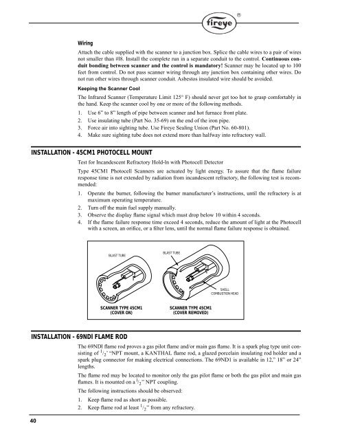
BLAST TUBE<br />
SCANNER TYPE 45CM1<br />
(COVER ON)<br />
BLAST TUBE<br />
SCANNER TYPE 45CM1<br />
(COVER REMOVED)<br />
INSTALLATION - 69NDl <strong>FLAME</strong> ROD<br />
The 69NDl flame rod proves a gas pilot flame and/or main gas flame. It is a spark plug type unit consisting<br />
of 1 / 2 ’ “NPT mount, a KANTHAL flame rod, a glazed porcelain insulating rod holder and a<br />
spark plug connector for making electrical connections. The 69ND1 is available in 12,” 18” or 24”<br />
lengths.<br />
The flame rod may be located to monitor only the gas pilot flame or both the gas pilot and main gas<br />
flames. It is mounted on a l / 2 ’’ NPT coupling.<br />
The following instructions should be observed:<br />
1. Keep flame rod as short as possible.<br />
2. Keep flame rod at least 1 / 2 ’’ from any refractory.<br />
®<br />
SHELL<br />
COMBUSTION HEAD